BA307E, BA327E, BA308E & BA328E intrinsically safe ... - Ex-Baltic
BA307E, BA327E, BA308E & BA328E intrinsically safe ... - Ex-Baltic
BA307E, BA327E, BA308E & BA328E intrinsically safe ... - Ex-Baltic
- No tags were found...

You also want an ePaper? Increase the reach of your titles
YUMPU automatically turns print PDFs into web optimized ePapers that Google loves.
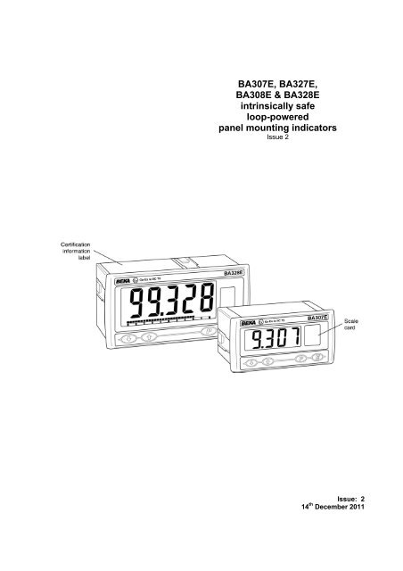
<strong>BA307E</strong>, <strong>BA327E</strong>,<strong>BA308E</strong> & <strong>BA328E</strong><strong>intrinsically</strong> <strong>safe</strong>loop-poweredpanel mounting indicatorsIssue 2Issue: 214 th December 2011
2CONTENTS1. Description2. Operation2.1 Controls3. Intrinsic <strong>safe</strong>ty certification3.1 ATEX gas certificate3.2 Zones, gas groups & T rating3.3 Special conditions for <strong>safe</strong> use3.4 4/20mA input3.5 Certification label information4. System Design for Gas HazardousAreas4.1 Transmitter loops4.2 Remote indication5. Installation5.1 Location5.2 EMC5.3 Installation procedure5.4 Scale card6. Configuration and Calibration6.1 Summary of configurationfunctions.6.2 Indicator function6.3 Resolution6.4 Position of decimal point6.5 Calibration using an externalcurrent source.6.6 Calibration using internalreference.6.7 Bargraph format and calibration6.8 Function of the P push-button6.9 Tare function6.10 Security code6.11 Under and over-range8. Maintenance8.1 Fault finding during commissioning8.2 Fault finding after commissioning8.3 Servicing8.4 Routine maintenance8.5 Guarantee8.6 Customer comments9. Accessories9.1 Scale card9.2 Tag strip9.3 Alarms9.3.1 Solid state output9.3.2 Intrinsic <strong>safe</strong>ty9.3.3 Configuration and adjustment.9.3.4 Alarm enable9.3.5 Setpoint adjustment9.3.6 Alarm function9.3.7 Alarm output status9.3.8 Hysteresis9.3.9 Alarm delay9.3.10 Alarm silence time9.3.11 Flash display when alarmoccurs.9.3.12 Access setpoint in displaymode.9.3.13 Adjusting alarm setpoint fromthe display mode.9.4 Display backlight9.4.1 Loop powering the backlight9.4.2 Separately powering thebacklight.Appendix 1 ATEX dust certificationAppendix 2 IEC<strong>Ex</strong> gas and dust certification7. Lineariser7.1 Lineariser calibration using an externalcurrent source.7.2 Lineariser calibration using internalreference.7.3 Lineariser error message7.4 Lineariser under and over-range7.5 Lineariser default configurationThe <strong>BA307E</strong>, <strong>BA327E</strong>, <strong>BA308E</strong> & <strong>BA328E</strong> are CE marked to show compliance with the European <strong>Ex</strong>plosiveAtmospheres Directive 94/9/EC and the European EMC Directive 2004/108/EC
31. DESCRIPTIONThese panel mounting, <strong>intrinsically</strong> <strong>safe</strong> digitalindicators display the current flowing in a 4/20mAloop in engineering units. They are loop poweredbut only introduce a 1.2V drop, which allows themto be installed into almost any 4/20mA currentloop. No additional power supply or battery isrequired.The four models are electrically similar, but havedifferent size displays and enclosures.Model Display Bezel size<strong>BA307E</strong> 4 digits 15mm high 96 x 48mm<strong>BA327E</strong> 5 digits 11mm high 96 x 48mmand bargraph.<strong>BA308E</strong> 4 digits 34mm high 144 x 72mm2. OPERATIONFig 1 shows a simplified block diagram of all themodels. The 4/20mA input current flows throughresistor R1 and forward biased diode D1. Thevoltage developed across D1, which is relativelyconstant, is multiplied by a switch mode powersupply and used to power the instrument. Thevoltage developed across R1, which is proportionalto the 4/20mA input current, provides the inputsignal for the analogue to digital converter.Each time a 4/20mA current is applied to theinstrument, initialisation is performed during whichall segments of the display are activated, after fiveseconds the instrument displays the input currentusing the calibration information stored in theinstrument memory. If the loop current is too lowto power the instrument the indicator will displaythe error message ‘LPLo’.<strong>BA328E</strong> 5 digits 29mm high 144 x 72mmand bargraph.This instruction manual supplements theinstruction sheet supplied with each instrument.The main application of all the models is to displaya measured variable or control signal in ahazardous process area. The zero and span ofthe display are independently adjustable so thatthe indicator can be calibrated to display anyvariable represented by the 4/20mA current, e.g.temperature, flow, pressure or level.All the models have been certified <strong>intrinsically</strong> <strong>safe</strong>for use in gas and dust hazardous areas byNotified Body Intertek Testing and Certification Ltdand comply with the European ATEX Directive94/9/EC. The EC-Type <strong>Ex</strong>amination certificatespecifies that under fault conditions the outputvoltage, current and power at the 4/20mA inputterminals will not exceed those specified for simpleapparatus in Clause 5.7 of EN 60079-11, whichsimplifies installation and documentation.Fig 1 Indicator block diagramFor international applications all models haveIEC<strong>Ex</strong> certification which is described inAppendix 2.
42.1 ControlsThe indicators are controlled and calibrated viafour front panel push-buttons located below thedisplay. In the display mode i.e. when theindicator is displaying a process variable, thesepush-buttons have the following functions:P While this button is pushed theindicator will display the input current inmA, or as a percentage of theinstrument span depending upon howthe indicator has been conditioned.When the button is released the normaldisplay in engineering units will return.The function of this push-button ismodified when optional alarms arefitted to the indicator.▼ While this button is pushed theindicator will display the numericalvalue and analogue bargraph* theindicator has been calibrated to displaywith a 4mA Φ input. When released thenormal display in engineering units willreturn.▲ While this button is pushed theindicator will display the numericalvalue and analogue bargraph* theindicator has been calibrated to displaywith a 20mA Φ input. When releasedthe normal display in engineering unitswill return.EP + ▼P + ▲No function in the display mode unlessthe tare function is being used.Firmware number followed by version.Direct access to the alarm setpointswhen optional alarms are fitted to theindicator and the ‘ACSP’ accesssetpoints in display mode function hasbeen enabled.P + E Access to configuration menu viaoptional security code.Note:* <strong>BA327E</strong> and <strong>BA328E</strong> onlyΦIf the indicator has been calibratedusing the CAL function, calibrationpoints may not be 4 and 20mA.3. INTRINSIC SAFETY CERTIFICATIONAll models have ATEX and IEC<strong>Ex</strong> gas and dustcertification. This section of the instruction manualdescribes ATEX gas certification. ATEX dust andIEC<strong>Ex</strong> approvals are described in Appendixes 1and 2.3.1 ATEX gas certificationAll the models have been issued with a commonEC-Type <strong>Ex</strong>amination Certificate numberITS11ATEX27254X by Notified Body IntertekTesting and Certification Ltd. This confirmscompliance with harmonised European standardsand it has been used to confirm compliance withthe European ATEX Directive for Group II,Category 1G equipment, <strong>Ex</strong> ia IIC T5 Ta = -40 to+70ºC. The indicators bear the community markand subject to local codes of practice may beinstalled in any of the European Economic Area(EEA) member countries. ATEX certificates arealso acceptable for installations in Switzerland.This section of the instruction manual describesATEX installations in explosive gas atmospheresconforming with EN60079-14 ElectricalInstallations design, selection and erection. Whendesigning systems for installation outside the UKthe local Code of Practice should be consulted.3.2 Zones, gas groups and T ratingThe indicators have been certified <strong>Ex</strong> ia IIC T5.When connected to a suitable system the indicatormay be installed in:Zone 0 explosive gas air mixturecontinuously present.Zone 1 explosive gas air mixture likelyto occur in normal operation.Zone 2 explosive gas air mixture notlikely to occur, and if it doeswill only exist for a short time.Be used with gases in groups:Group A propaneGroup B ethyleneGroup C hydrogenHaving a temperature classification of:T1 450 o CT2 300 o CT3 200 o CT4 135 o CT5 100 o CAt ambient temperatures between -40 and +70 o C.This allows the indicators to be installed in all gasZones and to be used with most common industrialgases.3.3 Special conditions for <strong>safe</strong> useThe ATEX certificate has an ‘X’ suffix indicatingthat special conditions apply for installations in IIICconductive dust atmospheres. No specialconditions apply to installations in gas or in IIIAand IIIB dust atmospheres. See Appendix 1 forinformation about use in dust atmospheres.
53.4 4/20mA inputThe input <strong>safe</strong>ty parameters for the 4/20mA input,terminals 1 and 3 are:Ui = 30V dcIi = 200mAPi = 0.84WThe maximum equivalent capacitance andinductance between the two 4/20mA inputterminals 1 and 3 is:Ci = 13nFLi = 8µHThe maximum permitted loop cable parameterscan be calculated by adding these figures to Ciand Li of other instruments in the loop andsubtracting the totals from the maximum cablecapacitance Co and cable inductance Lo permittedfor the Zener barrier or galvanic isolator poweringthe loop.Although the indicators do not themselves complywith the requirements for simple apparatus, theEC-Type <strong>Ex</strong>amination Certificate states that forintrinsic <strong>safe</strong>ty considerations, under faultconditions the output voltage, current and power atterminals 1 & 3 will not exceed those specified byclause 5.7 of EN 60079-11 for simple apparatus.This simplifies the application and intrinsic <strong>safe</strong>tydocumentation for loops containing theseindicators.4. SYSTEM DESIGN FOR GAS HAZARDOUSAREAS4.1 Transmitter loopsAll indicator models may be connected in serieswith almost any <strong>intrinsically</strong> <strong>safe</strong> 4/20mA currentloop and calibrated to display the measuredvariable or control signal in engineering units.There are two basic design requirements:1. The intrinsic <strong>safe</strong>ty output parameters of the4/20mA loop, which are defined by the Zenerbarrier or galvanic isolator powering the loop,must be equal to or less than:Uo = 30V dcIo = 200mAPo = 0.84W2. The loop must be able to tolerate theadditional 1.2V required to operate theindicator. When fitted with an optionalbacklight this increases to 5.0V if thebacklight is loop powered. See 9.4.1Figs 2a and 2b illustrate typical applications inwhich an indicator is connected in series with a2-wire transmitter powered by a Zener barrier andalternatively by a galvanic isolator.3.5 Certification label informationThe certification label is fitted in a recess on thetop outer surface of the instrument enclosure. Itshows the ATEX certification information,instrument serial number, year of manufacture plusBEKA associates' name and location. NonEuropean certification information may also beincluded, a typical label is shown below.Fig 2a Loop powered by a Zener barrier<strong>BA328E</strong> certification labelFig 2b Loop powered by a galvanic isolator
64.2 Remote indicationThe indicators may be driven via an <strong>intrinsically</strong><strong>safe</strong> interface from a 4/20mA <strong>safe</strong> area signal toprovide a remote display within a hazardous area.The type of <strong>intrinsically</strong> <strong>safe</strong> interface is not critical,either a Zener barrier or a galvanic isolator may beused, providing that Ui, Li and Pi of the indicatorare not exceeded and the voltage capability of the4/20mA signal is sufficient to drive the indicatorplus the interface.When a high integrity earth connection is alreadyavailable, a Zener barrier is usually the leastexpensive option. If an earth connection is notavailable or isolation is required, a galvanic isolatoris the correct choice.If one side of the 4/20mA current loop may beearthed, a single channel Zener barrier providesthe lowest cost protection. If the 4/20mA signal isnot isolated, then two Zener barriers, a twochannel Zener barrier or a galvanic isolator mustbe used.Fig 3 shows the alternative circuits which may beused.Fig 3 Alternative circuits for remote indicationin a hazardous area
75. INSTALLATION5.1 LocationAll the models have a robust glass reinforcedmodified PPO enclosure with a toughened glasswindow. The front of the indicator has IP66protection and a gasket seals the joint between theinstrument enclosure and the panel. The rear ofthe indicator has IP20 protection.The indicators may be installed in any panelproviding that the operating temperature isbetween –40ºC and +70ºC and intrinsic <strong>safe</strong>tyrequirements are complied with.Figs 4A and 4B show the overall dimensions of the96 x 48mm and the 144 x 72mm instrumentstogether with the recommended panel cut-outdimensions. To achieve an IP66 seal between theinstrument enclosure and the instrument panel thesmaller tolerance aperture must be used, and the144 x 72mm models must be secured with fourpanel mounting clamps.Although the indicator front panel provides IP66protection it should be shielded from direct sunlightand severe weather conditions.Fig 4B <strong>BA308E</strong> and <strong>BA328E</strong> dimensions5.2 EMCThe indicators comply with the requirements of theEuropean EMC Directive 2004/108/EC. Forspecified immunity all wiring should be in screenedtwisted pairs, with the screens earthed at one pointwithin the <strong>safe</strong> area.Fig 4A <strong>BA307E</strong> and <strong>BA327E</strong> dimensions
85.3 Installation Procedurea. Cut the specified aperture in the panel. Toachieve an IP66 seal between the instrumentenclosure and the instrument panel theaperture must have the tighter tolerancesspecified in Fig 4A and 4B.b. Slide the gasket over the body of theindicator before inserting the instrument intothe panel aperture.c. Firstly ensure that all the panel mountingclamps are closed by turning the knurledscrews fully anti clockwise until the two pipsin the clamp foot align with holes in the clampbody.d. Place a clamp in the recess on each side ofthe indicator, pulling gently to slide it onto thedovetail as shown in Fig 5. Push the knurledscrew slightly forward to engage the threadand tighten by turning clockwise until it is justfinger tight. When both clamps are fittedensure that the gasket behind the front panelbezel is correctly positioned before fullytightening the clamps to secure theinstrument. The maximum recommendedclamp tightening torque is 22cNm (1.95 lbf in)which is approximately equvalent to fingertightplus one half turn. Do not over tighten.e. Four panel mounting clamps are required toachieve an IP66 seal between a <strong>BA308E</strong> and<strong>BA328E</strong> indicator and the instrument panel.f. Connect the panel wiring to the rear terminalblock(s) as shown in Figs 4A and 4B. Tosimplify installation, the terminals areremovable so that the panel wiring can becompleted before the instrument is installed.5.4 Scale cardThe indicator’s units of measurement are shownon a printed scale card in a window at the righthand side of the display. The scale card ismounted on a flexible strip that is inserted into aslot at the rear of the instrument as shown in Fig 6.Thus the scale card can easily be changed withoutremoving the indicator from the panel or openingthe instrument enclosure.New indicators are supplied with a printed scalecard showing the requested units of measurement,if this information is not supplied when the indicatoris ordered a blank card will be fitted.A pack of self-adhesive scale cards printed withcommon units of measurement is available as anaccessory from BEKA associates. Custom printedscale cards can also be supplied.To change a scale card, unclip the protruding endof the flexible strip by gently pushing it upwardsand pulling it out of the enclosure. Peel theexisting scale card from the flexible strip andreplace it with a new printed card, which should bealigned as shown below. Do not fit a new scalecard on top of an existing card.Install the new scale card by gently pushing theflexible strip into the slot at the rear of the indicator,when it reaches the internal end-stop secure it bypushing the end of the flexible strip downwards sothat the tapered section is held by the rear panel.Align the selfadhesiveprintedscale card ontothe flexible stripand insert the stripinto the indicatoras shown below.Fig 5 Fitting panel mounting clampsFig 6 Inserting flexible strip carrying scale cardinto slot at the rear of indicator.
96. CONFIGURATION AND CALIBRATIONIndicators are configured and calibrated via thefour front panel push-buttons. All theconfiguration functions are contained in an easy touse intuitive menu that is shown diagrammaticallyin Fig 7.Each menu function is summarised in section 6.1and includes a reference to more detailedinformation. When the indicator is fitted with alarmsadditional functions are added to the menu whichare described in section 9.3Throughout this manual push-buttons are shownas P, E, ▼ or ▲, and legends displayed by theindicator are shown within inverted commas e.g.'CAL' and ' ALr2'.Access to the configuration menu is obtained byoperating the P and E push-buttonssimultaneously. If the indicator security code is setto the default 0000 the first parameter 'FunC' willbe displayed. If a security code other than thedefault code 0000 has already been entered, theindicator will display 'CodE'. Pressing the P buttonwill clear this prompt allowing each digit of thecode to be entered using the ▲ and ▼ pushbuttonsand the P button to move control to thenext digit. When the correct four digit code hasbeen entered pressing E will cause the firstparameter 'FunC' to be displayed. If the code isincorrect, or a button is not pressed within twentyseconds, the indicator will automatically return tothe display mode.Once within the configuration menu the requiredparameter can be reached by scrolling through themenu using the ▲ and ▼ push-buttons as shownin Fig 6. When returning to the display modefollowing recalibration or a change to any function,the indicator will display ‘dAtA’ followed by ‘SAVE’while the new information is stored in non-volatilememory.All new indicators are supplied calibrated asrequested at the time of ordering. If calibration isnot requested, indicators will be configured asfollows:<strong>BA307E</strong> <strong>BA327E</strong><strong>BA308E</strong> <strong>BA328E</strong>Access code ‘CodE’ 0000 0000Function ‘FunC’ Std StdDisplay at 4mA ‘Zero’ 0.0 0.00Display at 20mA ‘SPAn’ 100.0 100.00Resolution ‘rESn’ 1 digit 1 digitBargraph start ‘BarLo’ ----- 0.00Bargraph finish ‘BarHi’ ----- 100.00P button in display mode ‘C—P’ % %Tare ‘tArE’ Off OffDefault configuration can easily be changed onsite.6.1 Summary of configuration functionsThis section summarises each of the mainconfiguration functions and includes a crossreference to a more detailed description. Fig 7illustrates the location of each function within theconfiguration menu. The lineariser and theoptional factory fitted alarms are describedseparately in sections 7 and 9.3 of this manual.Display Summary of function'FunC''rESn''dP''CAL''SEt''bAr'Indicator functionDefines the relationship between the4/20mA input current and the indicatordisplay. May be set to:‘Std’ Standard linear relationship‘root’‘Lin’See section 6.2Square root extraction16 segment adjustablelineariser – see section 7.Display resolutionDefines the resolution of the leastsignificant display digit. May be set to‘1’, ‘2’, ‘5’ or ‘10’ digits.See section 6.3Decimal pointPositions a dummy decimal pointbetween any of the digits or turns it off.See section 6.4Calibration of the digital displayusing an external current source.Enables the zero and span of theindicator to be adjusted using anexternal current source such as acalibrator. When used with an accuratetraceable current source this is thepreferred method of calibration.See section 6.5Calibration of display using internalreferences.Enables the zero and span of theindicator to be adjusted without theneed for an accurate input current ordisconnection from the 4/20mA loop.See section 6.6Bargraph format and calibrationOnly <strong>BA327E</strong> & <strong>BA328E</strong> have bargraphThe bargraph may be conditioned tostart from left, right or centre of thedisplay, or it may be disabled. Whenoptional alarms are fitted it can alsodisplay both alarm setpoints and themeasured value.The bargraph may be calibrated to startand finish at any value within theindicator’s calibrated digital display.See section 6.7
11Display Summary of function'C - - P'Function of P push-buttonThe indicator may be configured todisplay the input current in milliamps, orthe input current as a percentage of the4/20mA input when the P push-buttonis operated in the display mode.See section 6.86.2 Indicator function: ‘FunC’This configuration function defines the relationshipbetween the indicator’s 4/20mA input current andthe indicator’s display. Three alternatives areavailable:‘Std’ Standard linear relationship‘root’‘Lin’Square root extraction16 segment adjustablelineariser.'tArE'Tare functionWhen enabled the tare function setsthe indicator display to zero when the Epush-button is operated in the displaymode.See section 6.9To reveal the existing indicator function select'FunC' from the configuration menu and press P.If the function is set as required, press E to returnto the menu, or press the ▲ or ▼ button to changethe setting, followed by the E button to return to theconfiguration menu.'CodE''rSEt'Security codeDefines a four digit numeric code thatmust be entered to gain access to theconfiguration menu. Default code 0000disables this security function andallows unrestricted access to allconditioning functions.See section 6.10ResetContains two sub-functions, ‘ConF’which returns the indicator to thedefault conditions and ‘LtAb’ whichreturns the lineariser to the defaultconditions. To prevent accidental useboth resets must be confirmed byentering ‘5urE’ before they will beexecuted.See section 6.11‘Std’‘root’LinearProvides a linear relationship between the4/20mA indicator input current and theindicator display.Square root extractionPrimarily intended to linearise the squarelaw 4/20mA output from differentialflowmeters.For reference, the following table showsthe output current from a non-lineariseddifferential flowmeter.% of full flow Current output mA2.5 4.0110.0 4.1625.0 5.0050.0 8.0075.0 13.00100.0 20.00When the root function is selected theindicator will display flow in linear units.‘Lin’16 segment adjustable lineariserEnables non linear variables to bedisplayed by the indicator in linearengineering units. Use of the lineariser isdescribed in section 7 of this instructionmanual.6.3 Resolution: rESnThis function defines the resolution of the leastsignificant display digit. Decreasing the displayresolution can improve the readability of a noisysignal. Select ''rESn' from the menu and press Pwhich will reveal the current display resolution. Tochange the resolution press the ▲ or ▼ button toselect 1, 2, 5 or 10 digits, followed by the E buttonto enter the selection and return to theconfiguration menu.
126.4 Position of the decimal point: ‘dP’A dummy decimal point can be positioned betweenany of the digits or it may be absent. To positionthe decimal point select 'dP' from the menu andpress P. The decimal point can be moved bypressing the ▲ or ▼ push-button. If a decimalpoint is not required it should be positioned beyondthe most or least significant digit. Whenpositioned as required press the E button to enterthe selection and return to the configuration menu.6.5 Calibration using an externalcurrent source: ‘CAL’This function enables the zero and span of theindicator to be adjusted using an externalcalibrated current source. When used with anaccurate traceable current source this is thepreferred method of calibration.Zero is the indicator display with 4mA inputSpan is the indicator display with 20mA inputTo calibrate the indicator select 'CAL' from theconfiguration menu and press P. The indicator willdisplay 'ZEro' which is a request for a 4mA inputcurrent. Adjust the external current calibrator to4.000mA and again press P which will reveal thecurrent zero display. The flashing digit of theindicator display can be changed by pressing the▲ or ▼ buttons, when set as required pressing Pwill transfer control to the next digit. When all thedigits have been adjusted, press E to enter thenew zero and return to the 'ZEro' prompt .Pressing the ▲ button will cause the indicator todisplay 'SPAn' which is a request for a 20mA inputcurrent. Adjust the external current calibrator to20.000mA and again press P which will reveal theexisting span display. The flashing digit of theindicator display can be changed by pressing the▲ or ▼ buttons, when set s required pressing Pwill transfer control to the next digit. When all thedigits have been adjusted press E to enter the newspan and return to the 'SPAn' prompt. Finallypress E again to return to the configuration menu.Notes:a. The indicator input current must be adjusted tothe required value before the zero and spanfunctions are entered by pressing the P button.b. Indicators may be calibrated at currents otherthan 4 and 20mA, withiin the range 3.8 to21.0mA providing the difference between thetwo currents is greater than 4mA. If theseconditions are not complied with, the indicatordisplays ‘FaiL’ and aborts the calibration.c. If the zero current is greater than the spancurrent the instrument will be reverse acting i.e.an increasing input current will cause thedisplay to decrease.6.6 Calibration using internal reference: ‘SEt’Using the ‘SEt’ function the indicator can becalibrated without the need for an accurateexternal current source and without the need todisconnect the indicator from the 4/20mAmeasuring loop.The indicator’s internal reference is used tosimulate a 4mA and 20mA input current, so theactual indicator input input current does not haveto be known during calibration.Zero is the display with a simulated 4mA inputSpan is the idisplay with a simulated 20mA inputTo calibrate the indicator display select 'SEt' fromthe configuration menu and press P. The indicatorwill display 'ZEro', pressing P again will reveal thecurrent display at 4mA. The flashing digit can beadjusted by pressing the ▲ or ▼ buttons, whenthe flashing digit is correct pressing P will transfercontrol to the next digit. When all the digits havebeen adjusted, press E to return to the 'ZEro'prompt.To adjust the display at 20mA, press the ▲ buttonwhich will cause the indicator to display 'SPAn',pressing P will then reveal the indicator’s exisitngdisplay at 20mA. The flashing digit can beadjusted by pressing the ▲ or ▼ buttons, whenthe flashing digit is correct pressing P will transfercontrol to the next digit. When all the digits havebeen adjusted press E to return to the 'SPAn'prompt followed by E to return to the ‘SEt’ promptin the configuration menu.6.7 Bargraph format and calibration: ‘bAr’Only <strong>BA327E</strong> & <strong>BA328E</strong> have a bargraphIn addition to a five digit numerical display the two<strong>BA327E</strong> and <strong>BA328E</strong> indicators have a 31segment analogue bargraph which may beconfigured to start and finish anywhere within theindicators numerical display range.To configure the bargraph select 'bAr' from theconfiguration menu and press P. The indicator willdisplay 'tYPE', pressing P again will reveal theexisting bargraph justification which can bechanged to one of the following four or five optionsusing the ▲ or ▼ button:Bargraph starts from‘LEFt’ Left end of display‘CEntr’ Centre of display‘riGHT’ Right end of display‘AlrSP’ Only with alarms – see section 9.3.14‘oFF’ Bargraph disabledWhen set as required press E to return to the‘tYPE’ sub-function prompt.
13The indicator’s digital display at which thebargraph starts is defined by the ‘bArLo’ subfunctionwhich is selected by pressing the ▲button followed by the P button which will revealthe current indicator display at which the bargraphstarts. The flashing digit can be adjusted bypressing the ▲ or ▼ buttons, when set as requiredpressing P will transfer control to the next digit.When all the digits have been adjusted, press E toreturn to the 'bArLo' prompt from which ‘bArHi’which defines the finishing point of the bargraphcan be selected by pressing the ▲ button. ‘bArHi’is adjusted in the same way as ‘bArLo’. When setas required, pressing E twice will return the displayto the ‘bAr’ prompt in the configuration menu.Note: ‘bArLo’ must be set lower than ‘bArHi’,incorrect setting is indicated by the bargraph scaleflashing with a single bargraph segment activated.6.8 Function of the P push-button: ‘C - - P’When the indicator is in the display mode,operating the P push-button will display the inputcurrent in milliamps, or the displayed value as apercentage of the difference between thedisplayed values at 4mA and 20mA inputs.To check or change the function of the P pushbuttonselect 'C - -P' from the configuration menuand press P to reveal the current setting. Pressingthe ▲ or ▼ button will toggle the setting between'4-20' the current display in milliamps and 'PC' thepercentage display. When set as required pressE to return to the ‘C - - P’ prompt in theconfiguration menu.6.9 Tare function: ‘tArE’The tare function is primarily intended for use withweighing system. When the indicator is in thedisplay mode and the tare function is activated,pressing the E button for more than three secondswill zero the indicator’s digital display and activatethe tare annunciator. On models with a bargraph,the bargraph remains linked to the digital displaywhen the tare function is activated. Subsequentoperation of the E push-button for less than 3seconds will return the indicator to the grossdisplay and deactivate the tare annunciator.To check or change the tare function select 'tARE'from the configuration menu and press P to revealthe current setting. Pressing the ▲ or ▼ buttonwill toggle the setting between 'on' and 'oFF'.When set as required press E to return to the‘tARE’ prompt in the configuration menu.6.10 Security code: ‘CodE’Access to the instrument configuration menu maybe protected by a four digit security code whichmust be entered to gain access. New instrumentsare configured with the default security code 0000which allows unrestricted access to allconfiguration functions.To enter a new security code select 'CodE' fromthe configuration menu and press P which willcause the indicator to display the existing securitycode with one digit flashing. The flashing digit canbe adjusted using the ▲ and ▼ push-buttons,when set as required operating the P button willtransfer control to the next digit. When all thedigits have been adjusted press E to return to the‘CodE’ prompt. The revised security code will beactivated when the indicator is returned to thedisplay mode. Please contact BEKA associatessales department if the security code is lost.6.11 Reset to factory defaults: ‘rSEt’This function enables the indicator and thelineariser to be quickly returned to the factorydefault configurations shown in sections 6 and 7.To reset the indicator or lineariser select ‘rSEt’from the configuration menu and press P, theindicator will display one of the reset options‘ConF’ or ‘LtAb’.‘ConF’‘LtAb’Resets the indicator to defaultsResets the lineariser to defaultsUsing the ▲ or ▼ push-button select the requiredsub-function and press P. To prevent accidentalresetting the request must be confirmed byentering ‘5urE’. Using the ▲ button set the firstflashing digit to ‘5’ and press P to transfer controlto the second digit which should be set to ‘u’.When ‘5urE’ has been entered pressing the Ebutton will reset the selected configuration menusand return the display to the ‘rSEt’ function in theconfiguration menu.6.12 Under and over-rangeIf the numerical display range of the indicator isexceeded, all the decimal points will flash asshown below:<strong>BA307E</strong> <strong>BA327E</strong><strong>BA308E</strong> <strong>BA328E</strong>Underrange -9.9.9.9 -9.9.9.9.9Overrange 9.9.9.9 9.9.9.9.9Although not guaranteed, most indicators willcontinue to function normally with an input currentbetween 1.8mA and 4mA, at lower currents theinstrument will display ‘LPLo’ before it stopsfunctioning.Under or overrange of the <strong>BA327E</strong> and <strong>BA328E</strong>bargraph is indicated by an activated arrow at theappropriate end of the bargraph and a flashingbargraph scale.
147. LINEARISERA sixteen segment, seventeen breakpoint (0 to 16)lineariser may be selected in the ‘FunC’ section ofthe configuration menu. The starting point andslope of each straight line segment are fullyadjustable allowing the indicator to display mostnon-linear process variables in linear engineeringunits. Each break-points must occur at a currentgreater than the preceeding break-point and lessthan the following break-point, in the range 3.8 to21.0mA Fig 8 shows a typical linearised indicatorcharacteristic.level sensor in an irregular tank may be displayedin linear volumetric units by filling the tank withknown incremental volumes and calibrating theindicator to display the sum of the increments ateach break-point.The number of break-points required should firstbe entered using the 'Add' and 'dEL' functions. Inboth these sub-functions the indicator initiallydisplays the current break-points and the totalnumber of break-points being used as shownbelow.Display'Add'Description of functionAdd a break-pointAdds a new break-point before thedisplayed break-point. The calibrationof existing break-points is not changed,but the identification number of allsubsequent break-points is increasedby one.Fig 8 shows a typical linearising characteristicSelecting ‘Lin’ in the ‘FunC’ section of theconfiguration menu activates the lineariser, thisdoes not change the configuration menu shown inFig 7, but the 'CAL' and 'SEt' functions areextended as shown in Fig 9. As with a linearindicator, calibration may be performed with anexternal current source using the 'CAL' function, orwith the internal reference using the 'SEt' function.The lineariser configuration is retained irrespectiveof how the the indicator function ‘FunC’ issubsequently changed. It is therefore possible toselect and deselect the lineariser without having toreconfigure it each time.7.1 Lineariser calibration using an externalcurrent source.This method allows direct calibration of thelineariser with an exteral current source and is thepreferred method when traceability is required. Ifthe exact system non-linearity is unknown, thismethod also allows direct calibration from thevariable to be displayed. e.g. the output from a'dEL'Remove a break-pointRemoves the displayed break-point andjoins the preceding break-point to thefollowing break-point with a straightline. The identification number of allsubsequent break-points is decreasedby one.To add a break-point using the ▲ or ▼ buttonselect 'CAL' from the configuration menu and pressP which will result in the 'Add' sub-function promptbeing displayed. To enter the sub-function press Pwhich will reveal the current break-point and thetotal number of break-point which have alreadybeen entered. Each subsequent operation of theP push-button will introduce an additional breakpointup to the maximum of 17. When adding abreak-point to a calibrated indicator, the insertionposition for the new break-point can be selectedusing the ▲ and ▼ push-buttons.The delete break-point sub-function 'dEL' operatesin exactly the same way as the 'Add' sub-functiondescribed above. Once within the ‘dEL’ subfunctioneach time the P button is pressed a breakpointis removed. When deleting a break-pointfrom a calibrated indicator, the break-point to bedeleted can be selected using the ▲ and ▼ pushbuttons.The minimum number of breakpointsis 2, break-points 0 and 1.
16When the required number of break-points havebeen entered, return to the linearisation sub-menuby pressing E. The indicator will display the 'Add'or 'dEL' prompt depending upon the last functionused.Now that the number of break-points has beenentered, the input current at which each occursand the corresponding indicator display can bedefined by the ‘Pts’ sub-function.Using the ▲ or ▼ button select 'PtS' from the submenuand press P which will select the first breakpoint'0 : n', where n is the total number of breakpointsentered. The selected break-point can bechanged using the ▲ and ▼ buttons. When therequired break-point has been selected, set theindicator input current to the exact value at whichthe break-point is required and press P. Thenusing the ▲ and ▼ buttons and the P button tomove between digits, enter the required indicatordisplay at this break-point.When set as required, press the E push-button toenter the required indicator display at this breakpointand return to the sub-menu from which thenext beak-point can be selected.'dEL''in''diSP'Remove a break-pointRemoves the displayed break-point andjoins the preceding break-point to thefollowing break-point with a straightline. The identification number of allsubsequent break-points is decreasedby one.Defines the current at which breakpointoccursEnables the required current at eachbreak-point to be defined withouthaving to input an accurate inputcurrent to the indicator.Defines indicator display at breakpointEnables the indicator display at eachbreak-point to be defined.The number of break-points required should firstbe entered using the 'Add' and 'dEL' subfunctions.In both these sub-functions the indicatorinitially displays the current break-point and thetotal number of break-point being used as shownbelow.When all the break-points have been calibratedpressing E twice will return the indicator to the‘CAL’ function in the configuration menu.Note: The indicator input current must be adjustedto the required value before the P button isoperated to enter the required indicator display.7.2 Lineariser calibration using the internalreference.The ‘SEt’ function enables the lineariser to becalibrated without the need for an accurateexternal current source. Throughout thecalibration the indicator input current may be anyvalue between 4 and 20mA.The ‘SEt’ functions contains four sub-functions.To add a break-point, using the ▲ or ▼ buttonselect 'SEt' from the configuration menu and pressP which will result in the 'Add' sub-function promptbeing displayed. To enter the sub-function press Pwhich will reveal the current break-point and thetotal number of break-points which have alreadybeen entered. Each subsequent operation of theP push-button will introduce an additional breakpointup to the maximum of 17. When adding abreak-point to a calibrated indicator, the insertionposition for the new break-point can be selectedusing the ▲ and ▼ push-buttons.Display'Add'Description of functionAdd a break-pointAdds a new break-point before thedisplayed break-point. The calibrationof existing break-points is not changed,but the identification number of allsubsequent break-points is increasedby one.The delete segment sub-function 'dEL' operates inexactly the same way as the 'Add' sub-functiondescribed above. Once within the ‘dEL’ functioneach time the P button is pressed a break-point isremoved. When deleting a break-point from acalibrated indicator, the break-point to be deletedcan be selected using the ▲ and ▼ push-buttons.The minimum number of break-points is 2, breakpoints0 and 1.
17When the required number of break-points hasbeen entered, return to the linearisation sub-menuby pressing E. The indicator will display the 'Add'or 'dEL' prompt depending upon the last subfunctionused. The indicator input current andcorresponding indicator display at each breakpoint,can now be entered using the ‘in’ and ‘diSP’sub-functions.Using the ▲ or ▼ button select 'in' from the submenuand press P which will reveal the first breakpoint'0 : n', where n is the total number of breakpointsentered. Press P and use the ▲ and ▼buttons and the P button to move between digits,to enter the input current at which the first breakpointis required, usually 4.000mA. When set asrequired, press E to return to the ‘0 : n’ promptfrom which the the next break-point can beselected using the ▲ and ▼ buttons. When therequired break-point has been selected press Pand enter the indicator input current at which thisbreak-point is required. Repeat this procedure untilthe indicator input current at all the break-pointshas been defined and then return to the ‘in’ subfunctionby pressing the E button.7.4 Under and over-rangeThe lineariser does not change the under andover-range indication described in section 6.12.At input currents below that specified for the firstbreak-point (0), the indicator will continue to usethe specified slope of the first segment. Althoughnot guaranteed, most indicators will continue tofunction normally with an input current between1.8mA and 4mA, at lower currents the instrumentwill display ‘LPLo’ before it stops functioning.At input currents above that specified for the lastbreak-point, the indicator will continue to use theslope specified for the last lineariser segment.7.5 Lineariser default configurationWhen the lineariser is reset to the defaultconditions using the ‘rSEt’ reset function describedin section 6.11, the defaults conditions are:<strong>BA307E</strong> <strong>BA327E</strong><strong>BA308E</strong> <strong>BA328E</strong>First break-point 4mA 0.0 0.00Second break-point 20mA 100.0 100.00The corresponding indicator display at each of thebreak-points can now be defined with the ‘diSP’sub-function Using the ▲ and ▼ buttons selectthe ‘diSP’ sub-function and press P which willreveal the first break-point '0 : n', where n is thetotal number of break-points entered. Press P anduse the ▲ and ▼ buttons and the P button tomove between digits, to enter the requiredindicator display at this first break-point. When setas required, press E to return to the ‘0 : n’ promptfrom which the the next break-point can beselected using the ▲ or ▼ buttons. When therequired break-point has been selected press Pand set the required indicator display at thisbreak-point.Repeat this procedure until the indicator display atall the break-points has been defined and thenreturn to the ‘SEt’ function in the configurationmenu by pressing the E button twice.7.3 Lineariser error messageIf an attempt is made to position a break-point at acurrent which is not greater than the current of thepreceeding break-point, or at a current which is notless than the current of the following break-point,the error message ‘FaiL’ will be displayed. Thiserror message will also be displayed if an attemptis made to position a break-point outside thecurrent range 3.8 to 21.0mA.
188. MAINTENANCE8.1 Fault finding during commissioningIf an indicator fails to function duringcommissioning the following procedure should befollowed:Symptom Cause SolutionNo display Incorrect wiring Check wiringNo display0V betweenterminals 1 & 3.All decimal pointsflashing.Unstable displayUnable to enterconfigurationmenu.Incorrect wiringor no powersupplyUnderrange if–ve signdisplayed oroverrange.4/20mA input isnoisy.Incorrectsecurity codeentered.There should be0.6 to 1.2Vbetween terminals1 & 3 with terminal1 positive.With an optionalloop poweredbacklight, thereshould be 3.4 to5V betweenterminals 1 & 13with terminal 1positive.Check supplyvoltage andvoltage dropcaused by all theinstruments in theloop.Recalibrate thenumerical display.Eliminate ripple on4/20mA powersupply and/ordecrease indicatorresolution.Enter correctsecurity code, orcontact BEKA ifthe code has beenlost.8.3 ServicingAll <strong>BA307E</strong>, <strong>BA327E</strong>, <strong>BA308E</strong> and <strong>BA328E</strong> looppowered indicators are interchangeable if therequired optional backlight and alarms are fitted. Asingle spare instrument may quickly berecalibrated to replace any instrument that isdamaged or fails. No attempt should be made torepair instruments at component level.We recommend that faulty instrumentsare returned to BEKA associates or toyour local BEKA agent for repair.8.4 Routine maintenanceThe mechanical condition of the instrument andelectrical calibration should be regularly checked.The interval between inspections depends uponenvironmental conditions. We recommend thatinitially instrument calibration should be checkedannually.8.5 GuaranteeIndicators which fail within the guarantee periodshould be returned to BEKA associates or our localagent. It is helpful if a brief description of the faultsymptoms is provided.8.6 Customer commentsBEKA associates is always pleased to receivecomments from customers about our products andservices. All communications are acknowledgedand whenever possible, suggestions areimplemented.8.2 Fault finding after commissioningENSURE PLANT SAFETY BEFORESTARTING MAINTENANCELive maintenance is permitted on<strong>intrinsically</strong> <strong>safe</strong> equipment installed in ahazardous area, but only certified testequipment should be used unless a gasclearance certificate is available.If an indicator fails after it has been functioningcorrectly follow the procedure shown in section8.1. If this does not reveal the cause of the fault, itis recommended that the instrument is replaced.This can be done without disconnecting power, butwhile the indicator is disconnected the 4/20mAloop will be open circuit.
199. ACCESSORIES9.1 Scale cardAll models have a window on the right hand side ofthe display through which to view a scale cardshowing the units of measurement such as o C,mBar, RPM. New indicators are fitted with a scalecard showing the units of measurement specifiedwhen the indicator was ordered, if the units are notspecified a blank scale card will be fitted. A packof scale cards pre-printed with common units ofmeasurement is available as an accessory. Thesecan easily be fitted on-site to the indicator withoutopening the indicator enclosure or removing it fromthe panel, See section 5.3 of this instructionmanual.Custom scale cards for applications requiring lesscommon units of measurement are also available.9.2 Tag informationNew indicators are supplied with tag or applicationinformation thermally printed onto the rear paneladjacent to the terminals, legend as specifiedwhen the indicator was ordered. This taginformation is not visible from the front of theinstrument after installation.9.3 AlarmsCAUTIONThese alarms outputs should not be used forcritical <strong>safe</strong>ty applications such as anemergency shut down system.All models can be supplied with factory fitted dualsolid state, single pole alarm outputs. Each alarmoutput may be independently conditioned as a highor low alarm with a normally open or normallyclosed output in the non-alarm condition.When the 4/20mA current powering the indicator isremoved both alarm outputs will open irrespectiveof configuration. The open circuit condition shouldtherefore be chosen as the alarm condition whendesigning an alarm system. Fig 10 illustrates theconditions available and shows which are fail <strong>safe</strong>.When an alarm occurs an alarm annunciator onthe indicator front panel is activated and if requiredthe numerical display can alternate between themeasured value and the alarm channelidentification ‘ALr1’ or ‘ALr2’.CAUTIONThe alarms are activated by the indicator’snumerical display. Use of the Tare Function‘tArE’ will change the numerical display, thealarms will continue to function at the originaldisplayed value, but this will correspond to adifferent input current.Fig 10 Alarm outputsConfigurable functions for each alarm includeadjustable setpoint, hysteresis, alarm delay andalarm accept.9.3.1 Solid state outputEach alarm has a galvanically isolated single polesolid state switch output which as shown in Fig 11.The output is polarised and current will only flow inone direction.Ron = less than 5Ω + 0.7VRoff = greater than 1MΩFig 11 Equivalent circuit of each alarm output9.3.2 Intrinsic <strong>safe</strong>tyEach alarm output is a separate galvanicallyisolated <strong>intrinsically</strong> <strong>safe</strong> circuit with output <strong>safe</strong>typarameters complying with the requirements forsimple apparatus. This allows the alarm outputterminals 8 & 9 and 10 & 11 to be connected toalmost any <strong>intrinsically</strong> <strong>safe</strong> circuit protected by aZener barrier or galvanic isolator providing theoutput parameters of the circuit do not exceed:Uo = 30V dcIo = 200mAPo = 0.84W
21The maximum equivalent capacitance andinductance between each set of alarm terminals is:Ci = 13nFLi = 8µHTo determine the maximum permissible cableparameters these figures should be subtractedfrom the maximum permitted cable capacitanceand inductance specified by the certificatepowering the alarm circuit, such as the solenoiddriver and switch transfer galvanic isolators shownin Fig 13.Summary of alarm configuration functionsDisplay Description of function'EnbL’Alarm enableEnables or disables the alarm withoutchanging the alarm parameters.See section 9.3.4'SP1' Alarm setpoint 1Adjusts the alarm setpoint. The alarmis activated when the indicator displayequals the setpoint.See section 9.3.5Fig 13 Typical alarm application(Shown without recommended screen cables)9.3.3 Configuration and adjustmentWhen optional alarms are fitted to a loop poweredindicator the configuration menu is extended asshown in Fig 12. The additional functions appearbetween the ‘SEt’ and the ‘C- - P’ functions for the<strong>BA307E</strong> and <strong>BA308E</strong> indicators, and between‘bAr’ and ‘C- -P’ for the <strong>BA327E</strong> and <strong>BA328E</strong>indicators. For simplicity, Fig 12 only shows theadditional functions for alarm 1, but alarm 2 hasidentical functions.The following table summaries each of the alarmconfiguration functions and includes a crossreference to more detailed information. Againonly the functions on alarm 1 are listed, but alarm2 has identical facilities'Hi.Lo''no.nC''HStr''dELA''SiL'‘FLSH’'ACSP'Alarm functionDefines the alarm function as High orLow.See section 9.3.6Normally open or normally closedoutputSets the alarm output open or closed inthe non-alarm condition.See section 9.3.7HysteresisAdjusts the alarm hysteresis.See section 9.3.8Alarm delay timeIntroduces adjustable delay betweenthe display equalling the setpoint andthe alarm output being activated.See section 9.3.9Alarm silence timeDefines the time that the alarm outputremains in the non-alarm conditionfollowing acceptance of an alarm.See section 9.3.10Flash display when alarm occursWhen enabled, alternates thenumerical display between processvalue and alarm reference, ‘ALr1’ or‘ALr2’, when an alarm output isactivated.See section 9.3.11Access setpointSub-menu which enables direct accessto the alarm setpoints from the indicatordisplay mode, and defines a separatesecurity code.See section 9.3.12
229.3.4 Alarm enable: ‘EnbL’This function allows each alarm to be enabled ordisabled without altering any of the alarmparameters. To enable or disable the alarm select'EnbL' from the alarm menu and press P which willreveal the current setting ‘on’ or ‘oFF’. Thefunction can be changed by pressing the ▲ or ▼button followed by the E button to return to thealarm menu.9.3.5 Setpoint adjustment: ‘SP1’ and ‘SP2’The setpoint of each alarm may be positionedanywhere in the numerical display of the indicatorproviding that this corresponds to an input currentbetween 3.8 and 20.2mA. e.g. If the indicator hasbeen calibrated to display 0 with 4mA input and10000 with 20mA input, the two alarm setpointsmay be positioned anywhere between -125 and10125.To adjust the setpoint select 'SP1' or 'SP2' from thealarm configuration menu and press P which willreveal the existing alarm setpoint. The flashingdigit of the setpoint can be adjusted using the ▲and ▼ push-buttons, and the P button to movecontrol to the next digit. When the requiredsetpoint has been entered press E to return to thealarm configuration menu.The alarm setpoints may also be adjusted whenthe indicator is in the display mode, see section9.3.12.9.3.6 Alarm function: ‘Hi.Lo’Each alarm can be independently conditioned as ahigh alarm or as a low alarm. To check or changethe alarm function select 'Hi.Lo' from the alarmmenu and press P to reveal the current setting.The function can be changed by pressing the ▲ or▼ button followed by the E button to return to thealarm menu.9.3.7 Alarm output status: ‘no.nC’Configures the solid state alarm output to be open‘no’ or to be closed ‘nC’ in the non-alarm condition.When deciding which is required, care should betaken to ensure that the alarm output is fail <strong>safe</strong> asillustrated in Fig 10.‘no’ Alarm output open in non-alarm condition‘nC’ Alarm output closed in non-alarm conditionCAUTIONWhen the 4/20mA supply is removedfrom the loop powered indicator, bothalarm outputs will open irrespective ofconditioning. Therefore for fail <strong>safe</strong>operation both alarm outputs should beconditioned to be open in the alarmcondition ‘nC’.To check or change the alarm output status, select'no.nC' from the alarm configuration menu andpress P to reveal the setting. The function may bechanged by pressing the ▲ or ▼ button followedby the E button to return to the alarm configurationmenu.9.3.8 Hysteresis: HStrHysteresis is shown in the units that the indicatorhas been calibrated to display.To adjust the hysteresis select 'HStr' from thealarm menu and press P which will reveal theexisting figure. The flashing digit can be adjustedusing the ▲ and ▼ push-buttons, and the Pbutton will move control to the next digit. When therequired hystersis has been entered press E toreturn to the alarm configuration menu.e.g. An indicator calibrated to display 0 to 10000,with a high alarm set at 9000 and hysteresis of 200will perform as follows:The high alarm will be activated whenincreasing indicator display equals 9000, butwill not reset until the indicator display fallsbelow 8800.9.3.9 Alarm delay: dELAThis function delays activation of the alarm outputfor an adjustable time following the alarm conditionoccurring. The delay can be set in 1 secondincrements between 0 and 3600 seconds. If adelay is not required zero should be entered. Toadjust the delay select 'dELA' from the alarmconfiguration menu and press P which will revealthe existing delay. The flashing digit of the delaycan be adjusted using the ▲ and ▼ push-buttons,and the P button to move control to the otherdigits. When the required delay has been enteredpress E to return to the alarm menu.e.g. An indicator with a high alarm set at 9000 andan alarm delay of 30 seconds will perform asfollows:The alarm annunciator will start to flash when anincreasing indicator display equals 9000, but thealarm output will not be activated until the alarmcondition has existed continuously for 30 seconds.When the alarm output is activated, the alarmannunciator will stop flashing and becomepermanently activated.If the ‘FLSH’ function, which flashes the indicatordisplay when an alarm occurs, has been enabled,it will not start to function until the alarm output isactivated.See section 9.3.11
239.3.10 Alarm silence time: SiLThis function is primarily intended for use in smallinstallations where the alarm output directlyoperates an alarm annunciator such as a sounderor beacon. When the alarm silence time, which isadjustable between 0 and 3600 seconds in 1second increments, is set to any figure other thanzero, the P push-button becomes an alarm acceptbutton. After an alarm has occurred, operating theP button will cause the alarm output to revert to thenon-alarm condition for the programmed alarmsilence time. If the alarm condition still exists atthe end of the silence time, the alarm output will bereactivated. During the silence time the indicatoralarm annunciator will flash until the silence timeexpires or the alarm is cleared.If the ‘FLSH’ function, which flashes the indicatordisplay when an alarm occurs has been enabled,it will only function when the alarm output isactivated, not during the silence time. See section9.3.11To adjust the alarm silence time select 'SiL' fromthe alarm configuration menu and press P whichwill reveal the existing silence time. The flashingdigit of the silence time can be adjusted using the▲ and ▼ push-buttons, and the P button to movecontrol to the other digits. When the requiredsilence time has been entered press E to return tothe alarm menu.9.3.11 Flash display when alarm occurs ‘FLSH’In addition to the two alarm annunciators on thetop left hand corner of the indicator display whichshow the status of both alarms, this functionprovides an even more conspicuous indication thatan alarm condition has occurred.When enabled, the function alternates the indicatordisplay between the numerical value and the alarmreference, ‘ALr1’ or ‘ALr2’, when the alarm outputis activated. If both alarm outputs are activated,the alarm references are displayed in sequence.To enable or disable the function select 'FLSH'from the alarm menu and press P which will revealthe current setting ‘on’ or ‘oFF’. The function canchanged by pressing the ▲ or ▼ button followedby the E button to return to the alarm menu.9.3.12 Access setpoint in display mode: ACSPThis function enables a separate menu providingaccess to the alarm setpoints from the displaymode by simultaneously operating the P and ▲push-buttons. An operator can therefore adjust thealarm setpoints without having access to theindicator configuration menu. Protection againstaccidental adjustment of the setpoints when theindicator is in the display mode is provided by aseparate security code.This direct setpoint access menu is enabled andthe separate security code entered from the'ACSP' function in the alarm configuration menu asshown in Fig 12. To change the menu parametersselect 'ACSP' from the configuration menu andpress P which will display the enable prompt'EnbL'. Press P again to reveal if the direct accessmenu is 'on' or 'oFF'. The ▲ or ▼ button willtoggle the display between the two conditions.If 'oFF' is selected, the operator will not haveaccess to the setpoints from the display mode.Return to the 'ACSP' prompt in the main menu bypressing E twice.If 'on' is selected, the operator will have directaccess to the alarm setpoints from the displaymode via a separate optional security code. Todefine this four digit security code press P to returnto the 'Enbl' prompt followed by the ▲ or ▼ buttonto select the access code prompt 'ACCd'.Pressing P will reveal the current security code.Each digit of the code may be changed byoperating the ▲ and ▼ push-buttons, and the Pbutton to move control to the next digit. When therequired code has been entered, press E twice toreturn to the 'ACSP' prompt in the configurationmenu.Default code 0000 will disable the security codeallowing direct access to the setpoints in thedisplay mode by pressing the P and ▲ buttonssimultaneously. Unless otherwise requested newinstruments with alarms are supplied with thisfunction disabled and the security code set to0000.9.3.13 Adjusting alarm setpoints from thedisplay modeAccess to the alarm setpoints from the indicatordisplay mode is obtained by operating the P and ▲push-buttons simultaneously as shown in Fig 14.If the setpoints are not protected by a securitycode the alarm setpoint prompt 'SP1' will bedisplayed. If the setpoints are protected by asecurity code, 'Code' will be displayed first.Pressing P again will enable the alarm securitycode to be entered digit by digit using the ▲ and▼ buttons to change the flashing digit, and the Ppush-button to move control to the next digit. If thecorrect code is entered pressing E will cause alarmsetpoint prompt 'SP1' to be displayed. Pressingthe ▲ or ▼ button will toggle the display betweenthe two alarm setpoint prompts 'SP1' and 'SP2'.If an incorrect security code is entered, or a buttonis not pressed within twenty seconds, the indicatorwill automatically return to the display mode.
249.3.14 Displaying setpoints on bargraphOne of the selectable bargraph formats ‘AlrSP’allows a low or a high setpoint plus the displayedvalue to be represented, or a low and a highsetpoint plus the displayed value to be representedby the bargraph as shown in Fig 15.Fig 15 Displayed value and setpoints on bargraphThe bargraph area below the low alarm setpointand the area above the high alarm setpoint areactivated. The displayed variable is representedby an activated bar which moves between theselow and high alarm setpoints.Fig 14 Setpoint adjustment from the display modeTo adjust an alarm setpoint select 'SP1' or 'SP2'and press P which will reveal the current setting.Each digit of the setpoint may be adjusted usingthe ▲ and ▼ push-buttons, and the P button tomove control to the next digit. When the requiredsetpoint has been entered, pressing E will returnthe display to the 'SP1' or 'SP2' prompt from whichthe other setpoint may be selected, or the indicatormay be returned to the display mode by pressing Eagain.When the activated bar representing the displayedvariable is adjacent to the area representing thelow or high ararm setpoints, the bar flashes.When a displayed variable equals the low or highalarm the complete bargraph representing theactivated alarm flashes irrespective of whether thealarm output has been delayed or cleared.For this function to operate SP1 must beconditioned as a low alarm and SP2 as a highalarm; SP1 must always be less than SP2.Incorrect configuration is shown by a flashingbargraph scale with no activated bars.Note: With the indicator in the display mode, directaccess to the alarm setpoints is only availablewhen the ACSP menu is enabled - see section9.3.12
259.4 Display backlightThe <strong>BA307E</strong>, <strong>BA327E</strong>, <strong>BA308E</strong> and <strong>BA328E</strong> looppowered indicators can be supplied with a factoryfitted backlight that may be loop or separatelypowered.When loop powered the backlight produces greenbackground illumination enabling the display to beread at night or in poor lighting conditions. Noadditional power supply, intrinsic <strong>safe</strong>ty interface orfield wiring are required, but the indicator voltagedrop is increased. When separately powered thebacklight is brighter, but an additional intrinsic<strong>safe</strong>ty interface and field wiring are required.described in sections 3 and 4 of this manualremain valid with the loop powered backlight.9.4.2 Separately powering the backlightThe optional backlight may also be powered from aseparate <strong>safe</strong> area power supply via an <strong>intrinsically</strong><strong>safe</strong> interface as shown in Fig 18.Fig 16 Terminals for optional backlight9.4.1 Loop powering the backlightThe backlight is loop powered by connecting it inseries with the indicator 4/20mA input as shown inFig 17, which increases the maximum indicatorvoltage drop from 1.2 to 5V.Fig 18 Separately powered backlightWhen separately powered the backlight draws aconstant current when supply is equal to or greaterthe minimum specified voltage. Below this supplyvoltage the backlight continues to function but withreduced brilliance.Current Minimum voltage<strong>BA307E</strong> & <strong>BA327E</strong> 22.5mA 9.0V<strong>BA308E</strong> & <strong>BA328E</strong> 34.7mA 11.0VAny certified Zener barrier or galvanic isolator maybe used, providing the output parameters do notexceed:Uo = 30V dcIo = 200mAPo = 0.84WFig 17 Loop powered backlightThe input intrinsic <strong>safe</strong>ty parameters of thecombined indicator and backlight are the same asfor the indicator alone. The EC-Type <strong>Ex</strong>aminationCertificate states that for intrinsic <strong>safe</strong>tyconsiderations, under fault conditions the outputvoltage, current and power of the combinedindicator and backlight terminals 1 & 13 will notexceed those specified by clause 5.7 of EN 60079-11 for simple apparatus, which simplifies systemdesign and documentation.Providing the increased voltage drop can betolerated, the intrinsic <strong>safe</strong>ty and system designThe following equivalent internal capacitance andinductance between terminals 12 & 14 should besubtracted from Co and Lo of the <strong>intrinsically</strong> <strong>safe</strong>interface powering the backlight to provide themaximum permissible cable parameters.Ci = 13nFLi = 8µHTwo separately powered <strong>BA307E</strong> or <strong>BA327E</strong>indicator backlights may be connected in parallel toa single channel 28V, 93mA Zener barrier orgalvanic isolator with no noticeable reduction inbrilliance on a 24V dc supply.
26Appendix 1Dust certificationA1.0 ATEX dust certificationIn addition to ATEX certification permittinginstallation in explosive gas atmospheres which isdescribed in the main section of this instructionmanual, all <strong>BA307E</strong>, <strong>BA327E</strong>, <strong>BA308E</strong> and<strong>BA328E</strong> indicators have ATEX certificationpermitting installation in combustible dustatmospheres.This appendix describes ATEX installations inexplosive dust atmospheres conforming withEN 60079-14 Electrical installations design,selection and erection. When designing systemsfor installation outside the UK the local Code ofPractice should be consulted.The indicator’s dust input and output <strong>safe</strong>typarameters are identical to gas parameters, so allthe electrical circuits shown in the main section ofthis manual may also be used for dustapplications.A1.1 Zones, and Maximum SurfaceTemperatureThe <strong>BA307E</strong>, <strong>BA327E</strong>, <strong>BA308E</strong> and the <strong>BA328E</strong>have been ATEX certified as Group II, Category1D <strong>Ex</strong> ia IIIC T80ºC Da IP20 apparatus, Ta -40 to70°C.When connected to a suitable system theindicators may be installed in:Zone 20Zone 21Zone 22explosive atmosphere in the form ofa cloud of combustible dust in air iscontinuously present, or for longperiods or frequently.explosive atmosphere in the form ofa cloud of combustible dust in air islikely to occur occasionally in normaloperation.explosive atmosphere in the form ofa cloud of combustible dust in air isnot likely to occur in normaloperation, but if it does occur, willonly persist for a short period.Be used with dust in subdivisions:Having a Minimum Ignition Temperature of:Dust cloud 120°CDust layer on indicatorup to 5mm thick155 ° CDust layer on indicator Refer toover 5mm thick. EN 60079-14At an ambient temperature between -40 and +70°CA1.3 MaintenanceENSURE PLANT SAFETY BEFORESTARTING MAINTENANCELive maintenance is permitted on<strong>intrinsically</strong> <strong>safe</strong> equipment installed in ahazardous area, but only certified testequipment should be used.All models have IP66 front of panel protection anda gasket is provided to seal the joint between theinstrument and the mounting panel thus preventingdust ingress from the outside of the mountingpanel. The rear of the instruments is not sealed,but ATEX dust certification is dependent on theinternal conformal coating of the instrument, sodust ingress is acceptable except for use in IIICconductive dusts – see A1.4. However, it is goodpractice to minimise the amount of dustaccumulating on the rear of the instrument.A1.4 Special conditions for use in IIIC dustsThe ATEX certificate for the loop poweredindicators has an ‘X’ suffix indicating that specialconditions for <strong>safe</strong> use are required for installion inIIIC dust atmospheres, the certificate states:‘For use in Group IIIC conductive gasatmospheres, the indicator shall bemounted such that the instrumentterminals have at least IP6X protection.’To prevent the indicator terminals becomingcontaminated by conductive dust:The indicator must be installed in a panel,cubicle or enclosure providing a minimum ofIP6X protection.IIIAIIIBIIICcombustible flyingsnon-conductive dustconductive dust(For use with IIIC conductive dustsspecial conditions for <strong>safe</strong> use apply– see section A1.4)The gasket supplied to seal the jointbetween the indicator and the mountingpanel must be used, and the 144 x 72mm<strong>BA308E</strong> and <strong>BA328E</strong> indicators must besecured with four panel mounting clamps.Note: These special installation conditions onlyapply for indicators exposed to IIIC conductive dustatmospheres.
27Appendix 2IEC<strong>Ex</strong> certificationA2.0 The IEC<strong>Ex</strong> Certification SchemeIEC<strong>Ex</strong> is a global certification scheme forexplosion protected products which aims toharmonise international certification standards.For additional information about the IEC<strong>Ex</strong>certification scheme and to view the BEKAassociate certificates, please visit www.iecex.comA2.1 IEC<strong>Ex</strong> Certificate of ConformityThe <strong>BA307E</strong>, <strong>BA327E</strong>, <strong>BA308E</strong> and the <strong>BA328E</strong>loop powered indicators and the optionalaccessories have been issued with an IEC<strong>Ex</strong>Certificate of Conformity numberIEC<strong>Ex</strong> ITS 11.0015X which specifies the followingcertification codes:<strong>Ex</strong> ia IIC T5 Ga<strong>Ex</strong> ia IIIC T80ºC DaTa = -40ºC to 70ºCThe specified gas and dust intrinsic <strong>safe</strong>typarameters are identical to the ATEX <strong>safe</strong>typarameters described in this manual.A2.3 Special conditions for use in IIIC dustsThe IEC<strong>Ex</strong> certificate for the loop poweredindicators has an ‘X’ suffix indicating that specialconditions for <strong>safe</strong> use are required for installion inIIIC dust atmospheres, the certificate states:‘For use in Group IIIC conductive gasatmospheres, the indicator shall bemounted such that the instrumentterminals have at least IP6X protection.’To prevent the indicator terminals becomingcontaminated by conductive dust:The indicator must be installed in a panel,cubicle or enclosure providing a minimum ofIP6X protection.The gasket supplied to seal the jointbetween the indicator and the mountingpanel must be used, and the 144 x 72mm<strong>BA308E</strong> and <strong>BA328E</strong> indicators must besecured with four panel mounting clamps.Note: These special installation conditions onlyapply for indicators exposed to IIIC conductive dustatmospheres.The IEC<strong>Ex</strong> certificate may be downloaded fromwww.beka.co.uk, www.iecex.com or requestedfrom the BEKA sales office.A2.2 InstallationThe IEC<strong>Ex</strong> and ATEX certificates specify identical<strong>safe</strong>ty parameters and installation requirements forboth approvals as defined by IEC / EN 60079-14.The ATEX gas and dust installation requirementsspecified in section 5 and Appendix 1 of thismanual may therefore be used for IEC<strong>Ex</strong>installations, but the local code of practice shouldalso be consulted.