
You also want an ePaper? Increase the reach of your titles
YUMPU automatically turns print PDFs into web optimized ePapers that Google loves.
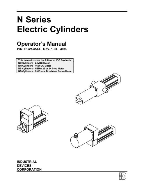
N Series<br />
Electric Cylinders<br />
Operator’s Manual<br />
P/N PCW-4544 Rev. 1.04 4/96<br />
This manual covers the following IDC Products:<br />
ND Cylinders - 24VDC Motor<br />
NH Cylinders - 160VDC Motor<br />
NS Cylinders - NEMA 23 or 34 Step Motor<br />
NB Cylinders - 23 Frame Brushless Servo Motor<br />
INDUSTRIAL<br />
DEVICES<br />
CORPORATION
Table of Contents<br />
Table of Contents<br />
1. PRODUCT OVERVIEW.......................................................................................................................1<br />
N SERIES CONTROL COMPATIBILITY CHART..................................................................................................1<br />
CYLINDER CONSTRUCTION..........................................................................................................................1<br />
CYLINDER PART NUMBER - IDENTIFY WHAT YOU HAVE ..................................................................................2<br />
2. MOUNTING / PERFORMANCE ..........................................................................................................4<br />
CYLINDER MOUNTING.................................................................................................................................4<br />
LOAD ATTACHMENT....................................................................................................................................4<br />
MOUNTING POSITION SENSORS - OVERTRAVEL PROTECTION .........................................................................6<br />
POSITION SENSOR SPECIFICATIONS.............................................................................................................7<br />
MAXIMUM THRUST AND NO-LOAD SPEED, BY MODEL NUMBER........................................................................8<br />
3. APPLICATION CONSIDERATIONS..................................................................................................10<br />
COLUMN LOADING....................................................................................................................................10<br />
CRITICAL SPEED ......................................................................................................................................10<br />
DUTY CYCLE LIMITS .................................................................................................................................11<br />
ENVIRONMENTAL SPECIFICATIONS .............................................................................................................11<br />
BACKDRIVING ..........................................................................................................................................11<br />
4. MOTOR WIRING / SPECIFICATIONS ..............................................................................................12<br />
D 24 VOLT DC MOTOR SPECIFICATIONS....................................................................................................12<br />
H 160VDC SERVO MOTOR SPECIFICATIONS ..............................................................................................13<br />
S21/S22/S23 HYBRID STEP MOTOR SPECIFICATIONS.................................................................................14<br />
S32/S33 HYBRID STEP MOTOR SPECIFICATIONS ........................................................................................15<br />
B23 BRUSHLESS SERVO MOTOR SPECIFICATIONS.......................................................................................16<br />
<strong>5.</strong> OPTIONS: WIRING AND SPECIFICATIONS....................................................................................17<br />
BRAKE (-BS) OPTION...............................................................................................................................17<br />
ENCODER (-EM) OPTION..........................................................................................................................18<br />
LINEAR POTENTIOMETER (-L) OPTION........................................................................................................19<br />
6. MAINTENANCE AND TROUBLESHOOTING...................................................................................20<br />
BASIC MAINTENANCE................................................................................................................................20<br />
Field Service..........................................................................................................................................20<br />
MAINTENANCE INSTRUCTIONS ...................................................................................................................20<br />
Lubricating the Leadscrew .....................................................................................................................20<br />
Lubricating Gears ..................................................................................................................................21<br />
Tensioning the Drive Belt.......................................................................................................................21<br />
FIELD SERVICE CHART .............................................................................................................................21<br />
TROUBLESHOOTING .................................................................................................................................22<br />
EXPLODED PARTS DIAGRAM......................................................................................................................24<br />
PARTS LIST FOR N SERIES CYLINDERS.......................................................................................................25<br />
WARRANTY AND SERVICE COVERAGE ........................................................................................................26<br />
Technical Support..................................................................................................................................26<br />
Factory Repair Service ..........................................................................................................................26
1. Product Overview<br />
Product Overview<br />
Industrial Devices Corporation (IDC) N Series Electric Cylinders are designed for use in a wide variety of<br />
industrial, scientific, and commercial applications requiring control of linear thrust, speed, or position.<br />
This operator’s manual will help you properly install and operate your N Series Cylinder.<br />
N Series Control Compatibility Chart<br />
IDC controls will optimize performance of N Series Cylinders. Please refer to the specific control<br />
operator’s manual for system operating instructions.<br />
Cylinder Type Compatible IDC Controls Cylinder <strong>Options</strong> Required<br />
ND D2200 Series<br />
D2300 Series<br />
D2500 Series *<br />
*<br />
requires -L Option<br />
NH H3301B<br />
H3951 †<br />
B8001<br />
B8961 †<br />
†<br />
requires -EM Option<br />
NS23x x = N, T, or V S6001<br />
S6002<br />
NS32x x = N, T, or V S6001<br />
S6002<br />
NB23 B8001<br />
B8501 *<br />
Cylinder Construction<br />
3<br />
2<br />
1<br />
B8962 †<br />
S6961<br />
S6962<br />
S6961<br />
S6962<br />
B8961<br />
B8962<br />
* requires -L Option<br />
4 5 6 7 8 9<br />
N Series Cylinder<br />
1. Motor 4. Thrust Bearings 7. Internal Guide Flange 9. Wiper Ring<br />
2. Bearing Housing <strong>5.</strong> Leadscrew (with magnets) 10. Thrust Tube<br />
3. Drive Train 6. Drive Nut 8. Rod End Sleeve Bearing 11. Guide Cylinder<br />
11<br />
10<br />
1
N Series Operator’s Manual<br />
2<br />
Cylinder Part Number - Identify What You Have<br />
Model Number Breakdown<br />
Industrial Devices Corp.<br />
64 Digital Drive, Novato, CA 94949<br />
1-800-747-0064 Fax: 415-883-2094<br />
Electric Cylinder Model:<br />
NH-105B-4-MP2-MT1-Q-W<br />
Serial Number: 950125 90048 1<br />
Voltage: V Rated Current: A<br />
Example:<br />
Base Model Number Stroke<br />
Length<br />
Rod-Type<br />
Cylinder<br />
N<br />
Motor<br />
Type<br />
Drive<br />
Ratio<br />
Screw<br />
Pitch,Type<br />
Location of Label shown on available Motor/Cylinder Mounting<br />
Configurations.<br />
Parallel Reverse Parallel Inline<br />
Label Label Label<br />
Cylinder<br />
Mounting<br />
Rod<br />
End<br />
<strong>Options</strong><br />
H 10 5B 4 MP2 MT1 Q W<br />
H = H Motor, 160VDC, 2 Amp, Permanent<br />
MP2 = Rear Double Clevis Mount<br />
Magnet<br />
10 = 1.0 to 1 Drive Ratio - Belt/Pulley MT1 = Male Threaded Rod End<br />
5B = 5 Pitch (.2”lead) Ballscrew Q = Quick Disconnect Option<br />
4 = 4 inch stroke W = Water Resistant Seal Option<br />
Base Model Number Stroke<br />
Length<br />
Rod-Type<br />
Cylinder<br />
N<br />
Motor<br />
Type<br />
Drive<br />
Ratio<br />
Screw<br />
Pitch,Type<br />
Cylinder<br />
Mounting<br />
Rod<br />
End<br />
1 2 3 4 5 6 7 8<br />
1 N Series Rod Type Cylinder<br />
2 Motor Type<br />
D 24VDC, 4.5 Amp, Permanent Magnet Motor<br />
H 160VDC, 2 Amp, Permanent Magnet Motor<br />
S23[x] NEMA 23 Frame, Step Motor, 3 Stack<br />
S32[x] NEMA 34 Frame, Step Motor, 2 Stack<br />
B23 23 Frame Brushless Servo Motor<br />
<strong>Options</strong><br />
[x] can be: N = 8 leads, windings can be wired in Series or Parallel<br />
T = Windings pre-wired in Series @ IDC Factory<br />
V = Windings pre-wired in Parallel @ IDC Factory<br />
3 Drive Ratio<br />
10 = 1.0:1 Drive Belt/Pulley<br />
15 = 1.5:1 Drive Belt/Pulley<br />
20 = 2.0:1 Drive Belt/Pulley<br />
25 = 2.5:1 Helical Gear<br />
31 = 3.1:1 Helical Gear<br />
35 = 3.5:1 Helical Gear<br />
120 = 12.0:1 Helical Gear<br />
99 = 1.0:1 Inline Coupling [Note: Direct 1:1 coupling is the only ratio available for Inline Models]
4 Screw Type<br />
2A = 2 Pitch (.5” lead) acme leadscrew<br />
5A = 5 Pitch (.2” lead) acme leadscrew<br />
8A = 8 Pitch (.125” lead) acme leadscrew<br />
10A = 10 Pitch (.1” lead) acme leadscrew<br />
2B = 2 Pitch (.5” lead) ballscrew<br />
5B = 5 Pitch (.2” lead) ballscrew<br />
5G = 5 Pitch (.2” lead) precision ground ballscrew<br />
5 Stroke Length<br />
(specified in inches)<br />
6 Mounting Styles<br />
MF1 = Front Rectangular Flange<br />
MF2 = Rear Rectangular Flange<br />
MF3 = Front & Rear Rectangular Flanges<br />
MP2 = Rear Double Clevis Mount<br />
MP3 = Rear Double Clevis Mount (w/ Pivot Base)<br />
MS1 = Side End Angles<br />
MS6 = Side Tapped Mounting Holes<br />
MT2 = Trunnion Mount<br />
MXA = Front Extended Stud Mount<br />
MXB = Rear Extended Stud Mount<br />
MXC = Front & Rear Extended Stud Mount<br />
(xxxM = Metric version of above option)<br />
7 Rod Ends<br />
FC2 = Clevis (includes MT1)<br />
FE2 = Female Eye (includes FT1)<br />
FS2 = Spherical Joint (includes FT1)<br />
FT1 = Female Thread<br />
MT1 = Male Thread<br />
(xxxM = Metric version of above option)<br />
8 Cylinder <strong>Options</strong><br />
BM = Brake on Motor<br />
BS = Brake on Leadscrew<br />
DB = Double Bearing<br />
EM = Encoder on Motor<br />
ES = Encoder on Leadscrew<br />
F = Subfreezing<br />
H = High Temperature<br />
HT = High Thrust<br />
L = Linear Potentiometer<br />
PB = Protective Boot<br />
PN = Pre-loaded Nut<br />
Q = Quick Disconnect<br />
RM = Reverse Parallel Motor Mounting<br />
W = Water Resistant Seal<br />
Mounting Styles<br />
-MF1, 2, 3 Rectangular Flanges<br />
-MP2 Rear Clevis<br />
-MS1 Side End Angles<br />
- MS6 Side-Tapped Holes<br />
Product Overview<br />
-MT2 Trunnions (Inline Models Only)<br />
Rod Ends<br />
-FC2 Clevis<br />
-FE2 Female Eye<br />
-FS2 Spherical Joint<br />
-FT1 Female Thread<br />
-MT1 Male Thread<br />
3
N Series Operator’s Manual<br />
2. Mounting / Performance<br />
4<br />
WARNING! Power to the electric cylinder should be OFF before attempting any physical installation or<br />
adjustments to the cylinder mounting, rod end attachments, or the load.<br />
Cylinder Mounting<br />
• The structure on which the cylinder is mounted should have ample strength to carry the maximum<br />
load and be rigid enough to prevent undue deflection or distortion of the cylinder or its supporting<br />
members.<br />
• The cylinder should be mounted parallel to the travel of the load to ensure proper alignment (this is<br />
especially important with externally guided loads using rails, bearings, etc.)<br />
• All mounting surfaces should be clean and flat to provide secure and stable fittings<br />
• Units with flat surface mounts (MF1, MF2, MF3, MS1, MS6) should be rigidly mounted.<br />
Mounting Description Recommendations<br />
MF1 Front Flange Not recommended for use in horizontal applications with<br />
stroke lengths greater than 12 inches unless there is<br />
additional support in the rear of the cylinder.<br />
MF2 Rear Flange Not recommended for use in horizontal applications with<br />
stroke lengths greater than 12 inches unless there is<br />
additional support in the front of the cylinder.<br />
MF3 Front and Rear Flange When securing to the Front and Rear Mounting flanges care<br />
should be taken to align the plates to their mating surfaces<br />
so as not to cause the body of the cylinder to twist.<br />
MP2 Rear Clevis Recommend using a flexible rod end or load attachment to<br />
compensate for any system misalignment.<br />
MS1 Side End Angle Bolts used to secure brackets should be able to withstand a<br />
Brackets<br />
shearing force in excess of 1000lbs.<br />
MS6 Side Tapped Holes Mounting screws used with side tapped holes should resist a<br />
peak shear force of up to 1000lbs. This mounting (alone) is<br />
not recommended for loads in excess of 500lbs.<br />
MT2 Trunnion Mount Recommend using a flexible rod end or load attachment to<br />
compensate for any system misalignment.<br />
MXA<br />
MXB<br />
MXC<br />
Load Attachment<br />
Extended Studs Important that the extended stud threads be torqued evenly<br />
when any attached fitting is secured.<br />
Do Not Apply Torque (Rotational Force) to Thrust Tube<br />
It is important that the thrust tube NOT be rotated to avoid<br />
damaging the internal plastic guide flange. This is especially<br />
important when attaching the rod end to the load. Two flats are<br />
provided at the end of the thrust tube to prevent rotation while the<br />
rod end attachments are secured.<br />
Torque<br />
Load
Mounting / Performance<br />
Special Notes for Mounting Rod-Ends to Load<br />
Rod End Description Recommendations<br />
FC2 Double Clevis<br />
Clevis should be securely fastened by lock nut once in<br />
(with MT1 Thread) desired location. In addition, the mounting pin should be<br />
secured with a cotter pin once it is inserted into the double<br />
clevis holes.<br />
FE2 Female Eye Adjust for maximum thread engagement.<br />
FS2 Spherical Joint Rotating joint compensates for any misalignment in the<br />
system. Not recommended when stiff or rigid load<br />
attachment is required.<br />
FT1 Female Thread Thread depth (of 3/8”) cannot be exceeded by the inserted<br />
member. Exceeding depth may cause contact with<br />
leadscrew or cause other internal damage when the thrust<br />
tube is fully retracted.<br />
MT1 Male Thread Any attached member should be secured in place by a lock<br />
nut once it is in the desired location<br />
Thrust Tube Side Load<br />
Thrust tube side loads create a bending force<br />
on the thrust tube sleeve bearing. If excessive,<br />
actuator performance and service life may be<br />
reduced. The side-load “bending moment”<br />
limit is a function of the perpendicular side<br />
load force and its extended length. The -DB<br />
Double Bearing option is provides additional<br />
bearing support, and is recommended for<br />
applications requiring more than 12” of travel.<br />
The side load limits shown below should not<br />
be exceeded.<br />
Side Load Moment<br />
(in-lbs)<br />
Top or Side of<br />
Cylinder Housing<br />
Side Load Capacity with Thrust Tube Extended to Various Lengths<br />
Side Load<br />
N Lbs<br />
359 80<br />
337<br />
311<br />
289<br />
267<br />
245<br />
222<br />
200<br />
178<br />
156<br />
133<br />
111<br />
89<br />
67<br />
44<br />
22<br />
0<br />
75<br />
70<br />
65<br />
60<br />
55<br />
50<br />
45<br />
40<br />
35<br />
30<br />
25<br />
20<br />
15<br />
10<br />
5<br />
0<br />
0<br />
0<br />
-DB MAX<br />
5<br />
127<br />
STANDARD MAX<br />
6<br />
4<br />
2<br />
8<br />
12 -DB<br />
8 -DB<br />
6 -DB<br />
4 -DB<br />
12<br />
18 -DB<br />
18<br />
24 -DB<br />
24<br />
10<br />
15 20 25<br />
254 381<br />
Extended Length<br />
508 635<br />
30<br />
762<br />
Extend Distance<br />
(inches)<br />
in<br />
mm<br />
Side Load (lbs)<br />
Sideplay<br />
5
N Series Operator’s Manual<br />
6<br />
Mounting Position Sensors - Overtravel Protection<br />
Although an “elastomeric spring” inside the actuator is designed to prevent actuator jams, position sensors<br />
(limit switches) are required to prevent such potentially damaging jam conditions. If the motor is<br />
accidentally commanded to move toward a hard-stop, position sensors can signal a stop before a collision<br />
occurs. To work properly, position sensors must be positioned inward from the hard-stop, and wired<br />
correctly to the motor controller.<br />
Note: Using the physical limits of the cylinder (hard stops) will reduce cylinder life and can cause premature component failure.<br />
Position Sensor Mounting Location - Deceleration Distance<br />
The position sensor’s location along the cylinder is associated with the beginning of a deceleration, not the<br />
final stopping point. Therefore, position sensors must be mounted inward of the cylinder hard-stops, so as<br />
to provide a slowdown area to prevent jamming. The faster the approach speed, the longer it takes to stop<br />
the cylinder, so deceleration distance varies with actuator speed, load, and cylinder/control type. Some<br />
adjustment may be necessary during initial setup.<br />
Position Sensor Mounting Dimensions<br />
RP1,RP2 0.73 [18.5]<br />
RPS-1, RPS-2 0.41 [10.4]<br />
SCREW<br />
TYPE<br />
ACME<br />
DIM<br />
"A"<br />
1.00<br />
BALL 1.40<br />
A<br />
"B"<br />
0.70<br />
0.30<br />
LOCKING SCREW, 5/64 HEX<br />
CABLE: 0.13 [3.3],<br />
0.25R [6.4R] MINIMUM<br />
BEND RADIUS<br />
0.57 [14.6]<br />
1.44 [36.6]<br />
B<br />
DIM NOTE: DIMENSIONS "A" AND "B" ARE APPROXIMATE<br />
END OF STROKE LOCATIONS FOR THE<br />
POSITION SENSORS.
Mounting / Performance<br />
Position Sensor Specifications<br />
(RP1, RP2, RPS-1, & RPS-2)<br />
Position sensors are available in normally open and normally closed versions. Hall Effect (RP1 / RP2) and<br />
Reed (RPS-1 / RPS-2) type switches are compatible with the N Series cylinders. Switches are activated by<br />
two internal position indicating magnets on opposite sides of the drivenut.<br />
• All sensors include a 12 ft [3.7m] shielded cable.<br />
• Recommended minimum distance between switches is 0.65 inches [16.5mm].<br />
• Sensors used for overtravel protection may reduce the available stroke, due to deceleration region.<br />
Position Sensor Specifications<br />
Magnetic Reed Switches Hall Effect Sensors<br />
Output Type Contact Closure Open Collector, Sinking Output<br />
Model # RPS-1 RPS-2 RP1 RP2<br />
Connection Normally Open Normally Closed Normally Open Normally Closed<br />
# of leads 2 Wire 2 Wire 3 Wire 3 Wire<br />
Voltage (VDC) 100VDC 100VDC 8 - 28VDC 8 - 28 VDC<br />
Voltage (VAC) 100VAC 100VAC ----- -----<br />
Current ( Amps) .25A .20A 40ma 40ma<br />
Power (Watts) 7W 2W 1.1W 1.1W<br />
Supply Voltage (VDC) ----- ----- 8 - 28VDC 8 - 28 VDC<br />
Supply Current (ma) ----- ----- 22ma 22ma<br />
Supply Power (watts) ----- ----- .6W .6W<br />
Operating Temperature -22° to 212°F (-30° to 100°C) -4° to 140°F (-20° to +60°C)<br />
Storage Temperature -22° to 212°F (-30° to 100°C) -22° to 176°F (-30° to 80°C)<br />
Humidity Rating 0 to 95% non-condensing 0 to 95% non-condensing<br />
Typical Wiring Diagram for RPS-1 and RPS-2<br />
RPS-1 or RPS-2<br />
12 ft, 2 conductor (22awg), shielded cable<br />
(leads are non-polarized)<br />
Red<br />
Black<br />
Shield<br />
Sinking Input<br />
Common<br />
External Device<br />
DC Supply<br />
Typical Wiring Diagram for RP1 and RP2<br />
RP1 or RP2<br />
Internal<br />
Sensor<br />
Red<br />
Brown<br />
Black<br />
Shield<br />
Power<br />
Sinking Input<br />
Common<br />
12 ft, 3 conductor (22awg), shielded cable<br />
External Device<br />
DC Supply<br />
7
N Series Operator’s Manual<br />
8<br />
Maximum Thrust and No-Load Speed, by Model Number<br />
The following charts indicate the MAXIMUM THRUST and NO-LOAD SPEEDS for a given model<br />
number. Detailed Thrust, Speed and Duty Cycle performance curves can be found in the IDC Electric<br />
Linear Actuators & Controls Catalog.<br />
• See Chapter 3 - Application Considerations, for speed and thrust limitations due to stroke length.<br />
ND Series<br />
Cylinder Thrust Speed Cylinder Thrust Speed<br />
Model lbs [N] in/sec [mm/s] Model lbs [N] in/sec [mm/s]<br />
ND-102B 34[151] 24.0[610] ND-105A 35[156] 10.0[254]<br />
ND-152B 55[244] 16.0[406] ND-155A 70[311] 7.0[178]<br />
ND-202B 70[311] 14.0[356] ND-205A 105[467] 6.0[152]<br />
ND-352B --- --- ND-355A 190[845] 3.5[89]<br />
ND-1202B --- --- ND-1205A 500[2224] 1.0[25]<br />
ND-992B 34[151] 24.0[610] ND-995A 35[156] 10.0[254]<br />
ND-105B 85 [378] 10.0[254] ND-108A 50[222] 6.0[152]<br />
ND-155B 126 [560] 7.0[178] ND-158A 90[400] 4.5[114]<br />
ND-205B 193 [859] 6.5[165] ND-208A 150[667] 3.5[89]<br />
ND-355B 365 [1623] 3.5[89] ND-358A 275[1223] 3.0[76]<br />
ND-1205B 800 [3559] 1.0[25] ND-1208A 800[3559] .6[15]<br />
ND-995B 85 [378] 10.0[254] ND-998A 50[222] 6.0[152]<br />
Note: Values are based on operation with D2200 or D2300 Series controls, for operation with D2500 Series Controls reduce max<br />
thrust by 50%.<br />
NH Series<br />
Cylinder Thrust Speed Cylinder Thrust Speed<br />
Model lbs [N] in/sec [mm/s] Model lbs [N] in/sec [mm/s]<br />
NH-102B 135[601] 30.0[762] NH-105A 150[667] 12.0[305]<br />
NH-152B 200[890] 16.0[406] NH-155A 220[977] 8.0[203]<br />
NH-202B --- --- NH-205A 290[1290] 6.0[152]<br />
NH-352B --- --- NH-315A 375[1668] 3.9[99]<br />
NH-992B 135[601] 30.0[762] NH-995A 150[667] 12.0[305]<br />
NH-105B 350[1557] 12.0[305] NH-108A 230[1023] 7.5[191]<br />
NH-155B 550[2447] 8.0[203] NH-158A 360[1601] 4.5[114]<br />
NH-205B 700[3114] 6.0[152] NH-208A 475[2113] 3.8[97]<br />
NH-315B 800[3559] 3.9[99] NH-318A 600[2669] 2.4[61]<br />
NH-995B 350[1557] 12.0[305] NH-998A 230[1023] 7.5[191]<br />
Note: Values are based on operation with H3000 or B8000 Series Controls<br />
NS23 Series<br />
Cylinder Thrust Speed Cylinder Thrust Speed<br />
Model lbs [N] in/sec [mm/s] Model lbs [N] in/sec [mm/s]<br />
NS23x-102B 65[289] 2<strong>5.</strong>0[635] NS23x-105A 90[400] 10.0[254]<br />
NS23x-152B 100[445] 17.0[432] NS23x-155A 135[601] 6.7[170]<br />
NS23x-202B --- --- NS23x-205A 180[801] <strong>5.</strong>0[127]<br />
NS23x-352B --- --- NS23x-355A 245[1090] 2.9[74]<br />
NS23x-1202B --- --- NS23x-1205A 720[3203] .8[20]<br />
NS23x-992B 65[289] 2<strong>5.</strong>0[635] NS23x-995A 90[400] 10.0[254]<br />
Notes: Values are based on operation with S6000 Series Controls. x can be N, T, or V which indicates motor wiring configuration.
Mounting / Performance<br />
NS23 Series (continued)<br />
Cylinder Thrust Speed Cylinder Thrust Speed<br />
Model lbs [N] in/sec [mm/s] Model lbs [N] in/sec [mm/s]<br />
NS23x-105B 165[734] 10.0[254] NS23x-108A 144[641] 6.3[160]<br />
NS23x-155B 250[1112] 6.7[170] NS23x-158A 216[961] 4.2[107]<br />
NS23x-205B 330[1468] <strong>5.</strong>0[127] NS23x-208A 288[1281] 3.1[79]<br />
NS23x-355B 450[2002] 2.9[74] NS23x-358A 392[1744] 1.8[46]<br />
NS23x-1205B 800[3559] .8[20] NS23x-1208A 800[3559] .52[13]<br />
NS23x-995B 90[400] 10.0[254] NS23x-998A 144[641] 6.3[160]<br />
Notes: Values are based on operation with S6000 Series Controls. x can be N, T, or V which indicates motor wiring configuration.<br />
NS32 Series<br />
Cylinder Thrust Speed Cylinder Thrust Speed<br />
Model lbs [N] in/sec [mm/s] Model lbs [N] in/sec [mm/s]<br />
NS32x-102B 145[645] 2<strong>5.</strong>0[635] NS32x-105A 180[801] 10.0[254]<br />
NS32x-152B 219[974] 17.0[432] NS32x-155A 270[1201] 6.7[170]<br />
NS32x-252B --- --- NS32x-255A 400[1779] 4.0[102]<br />
NS32x-992B 145[645] 2<strong>5.</strong>0[635] NS32x-995A 180[801] 10.0[254]<br />
NS32x-105B 365[1624] 10.0[254] NS32x-108A 288[1281] 6.3[160]<br />
NS32x-155B 550[2447] 6.7[170] NS32x-158A 432[1922] 4.2[107]<br />
NS32x-255B 800[3559] 4.0[102] NS32x-258A 640[2847] 2.5[64]<br />
NS32x-995B 365[1624] 10.0[254] NS32x-998A 288[1281] 6.3[160]<br />
Notes: Values are based on operation with S6000 Series Controls. x can be N, T, or V which indicates motor wiring configuration.<br />
NB23 Series<br />
Cylinder Thrust Speed Cylinder Thrust Speed<br />
Model lbs [N] in/sec [mm/s] Model lbs [N] in/sec [mm/s]<br />
NB23-102B 280[1246] 30.0[762] NB23-105A 306[1361] 12.0[305]<br />
NB23-152B 420[1868] 20.0[508] NB23-155A 360[1601] 8.0[203]<br />
NB23-202B 560[2491] 1<strong>5.</strong>0[381] NB23-205A 613[2727] 6.0[152]<br />
NB23-252B --- --- NB23-315A 660[2936] 3.9[99]<br />
NB23-312B --- --- NB23-995A 306[1361] 12.0[305]<br />
NB23-992B 280[1246] 30.0[762]<br />
NB23-105B 700[3114] 12.0[305] NB23-108A 491[2184] 7.5[191]<br />
NB23-155B 800[3559] 8.0[203] NB23-158A 736[3274] <strong>5.</strong>0[127]<br />
NB23-205B 800[3559] 6.0[152] NB23-208A 800[3559] 3.8[97]<br />
NB23-255B 800[3559] 4.8[122] NB23-318A 800[3559] 2.4[61]<br />
NB23-315B 800[3559] 3.9[99] NB23-998A 491[2184] 7.5[191]<br />
NB23-995B 700[3114] 12.0[305]<br />
Notes: Values are based on operation with B8000 Series Controls.<br />
9
N Series Operator’s Manual<br />
3. Application Considerations<br />
10<br />
Certain conditions can limit cylinder performance and should be addressed prior to installation and<br />
operation. Please review the following information to insure that your cylinder has been properly applied in<br />
your machine design.<br />
Column Loading<br />
Compression (column) Load<br />
Thrust<br />
Load<br />
All leadscrews have a column loading limit which causes the screw to buckle or bend as thrust load<br />
increases. This limit is a function of unsupported leadscrew length. Exceeding this limit will cause the<br />
leadscrew to buckle and become permanently damaged.<br />
Thrust Load Limitations Due to Length<br />
Cylinder Stroke Length (inches)<br />
Screw Type 800 >800 >800 780 540 400 305<br />
[>3559] [>3559] [>3559] [3470] [2402] [1779] [1356]<br />
5A >800 700 395 250 175 130 95<br />
[>3559] [3114] [1757] [1112] [778] [578] [423]<br />
8A >800 >800 >800 545 380 280 210<br />
[>3559] [>3559] [>3559] [2424] [1690] [1246] [934]<br />
Note: Above loads are in lbs [N]<br />
Critical Speed<br />
L<br />
All leadscrew systems have a rotational speed limit where harmonic vibrations occur. This limit is a<br />
function of unsupported leadscrew length. Sustained operation beyond this critical speed will cause the<br />
leadscrew to vibrate (whip violently), eventually bending or warping the screw.<br />
Speed Limitations Due to Length<br />
Cylinder Stroke Length (inches)<br />
Screw Type
Duty Cycle Limits<br />
Application Considerations<br />
Duty Cycle is the percentage of On Time divided by Total Cycle Time for the worst case 10 minute period.<br />
During operation, it represents the maximum acceptable power dissipation of the motor and the frictional<br />
heat losses of the internal cylinder components, primarily the leadscrew/drivenut assembly. In general,<br />
ballscrew actuators are rated for 100% duty cycle and acme screws are rated for a maximum of 60%.<br />
Exceeding the recommended duty cycle will damage the motor or internal cylinder components. Consult<br />
IDC Electric Linear Actuators & Controls Catalog for individual model number ratings.<br />
Environmental Specifications<br />
Temperature Ratings<br />
Standard Actuator 32° to 140°F [0° to 60°C]<br />
-H High Temp. option 32° to 160°F [0 to 71°C] (extends high temp. limit)<br />
-F Sub-Freezing option -20° to 105°F [-29° to 41°C] (allows low temp., but decreases<br />
high temp. limit)<br />
Contaminants<br />
Liquids: Standard N Series Cylinders are not water (nor any liquid) resistant. If liquid or moisture<br />
contaminates internal components, damage may occur. A Water Resistant option (-W) is available for<br />
environments with a slight mist or spray. The Protective Boot option (-PB), which includes the -W<br />
sealing option is available to protect the thrust tube/wiper interface.<br />
For applications where exposure is unavoidable with a corrosive liquid or a pressurized liquid, an<br />
external protective enclosure is recommended. Consult the factory for assistance.<br />
Solid Particles: Rod-type cylinders are generally well protected against particle contaminants. For<br />
environments with exposure to fine or abrasive particles, the Water Resistant (-W) option provides added<br />
resistance to entry, by sealing mating surfaces with RTV during assembly. The Protective Boot (-PB)<br />
option is recommended when the thrust tube/sleeve bearing interface is exposed to abrasive particles.<br />
Backdriving<br />
Backdriving is when the thrust tube is forced to extend or retract by an external force. This is an important<br />
consideration for cylinders being used in a vertical orientation or when a external thrust load is applied to<br />
the cylinder. A cylinder (without motor holding torque) will hold position up to the thrust limit known as<br />
the backdrive limit (determined by the screw type and pitch used). The IDC Electric Linear Actuators &<br />
Controls Catalog shows backdrive force limits for each individual cylinder model. Acme screws, due to<br />
their inherent self-locking action, have considerably higher limits than ballscrew driven actuators.<br />
Screw Type Description Load Required to Backdrive<br />
Ballscrew 2B: 2 Pitch, 0.500” lead 10 - 15 lbs [45 - 67 N]<br />
5B: 5 Pitch, 0.200” lead 20 - 25 lbs [89 - 111N]<br />
Acme Screw 5A: 5 Pitch, 0.200” lead 100 - 400 lbs [440 - 1800N]<br />
8A: 8 Pitch, 0.125” lead 600 - 800 lbs [2700 - 3600N]<br />
11
N Series Operator’s Manual<br />
4. Motor Wiring / Specifications<br />
D 24 Volt DC Motor Specifications<br />
Motor Type: Permanent Magnet 2-Pole<br />
Standard (Single Shaft)<br />
12<br />
Motor Data<br />
1.25<br />
(31.75)<br />
dia (2)<br />
0.12<br />
(3.05)<br />
10°<br />
4.135 +<br />
- 0.060<br />
(10<strong>5.</strong>03 +<br />
- 1.524)<br />
Inline (Double Shaft)<br />
Red & black 16 AWG<br />
18 (457) min length<br />
105¡C UL approved<br />
2.25 (57.2) SQ<br />
0.12<br />
(3.05)<br />
4X ø0.21 (<strong>5.</strong>33) thru<br />
2X 4-40 UNC-2B X .25 (6.35) deep<br />
Equally spaced on ø1.812 (46.0) B.C.<br />
0.3125 (7.936)<br />
0.3115 (7.912) dia<br />
10-32 UNF-2B thru<br />
2 places eq spaced<br />
on a 2.000 (50.80)<br />
dia B.C.<br />
1.187 +<br />
- 0.060<br />
(30.15 +<br />
- 1.524)<br />
Red & black<br />
16 AWG leads<br />
6.0 (152.40)<br />
min lg.<br />
4.71 (119.6)<br />
45<br />
2.750<br />
(69.85)<br />
dia<br />
0.68 (17.3) 0.81 (20.6)<br />
45<br />
0.575<br />
(14.61)<br />
R<br />
ø.2500/.2495<br />
ø.2500/.2495<br />
(6.350/6.337) (6.350/6.337)<br />
Electrical Mechanical<br />
Rated Voltage V 24 Continuous Stall Torque oz-in 40<br />
Max. Continuous Current A 4.5 No-load Speed at Rated Voltage RPM 3600<br />
Max. Operating Voltage V 36 No-load Current A 0.5<br />
Inductance mH 2.0 Rotor Inertia oz-in-s 2<br />
0.018<br />
Kt Torque Constant oz-in/A 8.9 ± 10% Max. Winding Temperature °C 82<br />
Kv Voltage Constant V/kRPM 6.5 Weight lbs [kg]<br />
Winding Resistance @ Ambient ohms 1.0<br />
Motor Wiring<br />
Motor<br />
Supply<br />
Voltage<br />
Motor Positive Lead<br />
Motor Negative Lead<br />
Earth Ground<br />
M+<br />
M-<br />
Red (White with -Q Cable)<br />
Black<br />
Green<br />
37<br />
Motor<br />
Case Ground
H 160VDC Servo Motor Specifications<br />
Motor Type: Permanent Magnet 2-Pole<br />
Motor Data<br />
0.875<br />
(2.2)<br />
R<br />
37<br />
0.500<br />
(12.7) dia<br />
0.3125<br />
0.3120<br />
0.002 (0.05)<br />
1.21 (30.7)<br />
1.17 (29.7)<br />
(7.94)<br />
-A-<br />
(7.92)<br />
0.03<br />
(0.8) R<br />
both ends<br />
3.00<br />
(76.2)<br />
Dia both ends<br />
10-32 UNF-2B x 0.40 (10.2) min deep<br />
2 places opposite on a 2.625 (66.7) dia B.C.<br />
0.15 (3.8)<br />
<strong>5.</strong>687 (144.4)<br />
<strong>5.</strong>625 (142.9)<br />
A 0.005 (0.013) -B-<br />
Red & black 18 AWG leads<br />
12.0 (304.8) min lg.<br />
1.50<br />
(38.1)<br />
10-32 UNF-2B x 0.40 (10.2) min deep<br />
2 places opposite on a 2.000 (50.8) dia B.C.<br />
Note:<br />
Rotation:<br />
CCW viewed from<br />
lead end with red<br />
lead positive.<br />
0.2500<br />
0.2494<br />
B 0.0012 (0.030)<br />
0.001 (0.025)<br />
(6.35)<br />
(6.33) dia<br />
3.125<br />
(79.4)<br />
dia<br />
Motor Wiring / Specifications<br />
0.75<br />
0.71 (19.1)<br />
(18.0)<br />
3.57<br />
(90.7)<br />
4-40 UNC-2B x 0.30 (7.6) min deep<br />
2 places opposite on a 1.812 (46.0) dia B.C.<br />
8-32 UNC-2B x 0.30 (7.6) min deep<br />
2 places opposite on a 2.125 (54.0) dia B.C.<br />
Electrical Mechanical<br />
Rated Voltage V 160 Continuous Stall Torque oz-in 108<br />
Max. Operating Voltage V 180 No-load Speed at Rated Voltage RPM 3900<br />
Max. Continuous Current A 2.0 Rotor Inertia oz-in-s 2<br />
0.049<br />
Max. No-load Current A 0.22 Max. Winding Temperature °C 82<br />
Inductance mH 25 Weight lbs [kg]<br />
Winding Resistance @ Ambient ohms 6.4<br />
Kt Torque Constant oz-in/A 54 ± 10%<br />
Kv Voltage Constant V/kRPM 40<br />
Motor Wiring<br />
Motor<br />
Supply<br />
Voltage<br />
Motor Positive Lead<br />
Motor Negative Lead<br />
Earth Ground<br />
M+<br />
M-<br />
Red (White with -Q Cable)<br />
Black<br />
Green<br />
Motor<br />
Case Ground<br />
13
N Series Operator’s Manual<br />
S21/S22/S23 Hybrid Step Motor Specifications<br />
Motor Data<br />
Electrical<br />
14<br />
4-40UNC-2B THRU<br />
ON 1.812 B.C. (2)<br />
(8) #24 AWG LEADS<br />
12 FEET LONG<br />
∅0.2500/0.2495<br />
S21 : 2.02 / S22 : 3.02 / S23 : 4.02<br />
0.79/0.71<br />
S21T<br />
(Series)<br />
0.84/0.78<br />
0.19<br />
0.70 FULL FLAT<br />
0.06<br />
S21V<br />
(Parallel)<br />
S22T<br />
(Series)<br />
∅0.2500/0.2495<br />
∅0.195/0.215 0.195/0.215 THRU (4)<br />
ON A ∅2.625 B.C.<br />
∅1.502/1.498<br />
S22V<br />
(Parallel)<br />
0.219<br />
1.856 SQ REF<br />
S23T<br />
(Series)<br />
2.27 SQ MAX<br />
Continuous Stall Torque oz-in [N-m] 65 [0.46] 100 [0.71] 125 [0.88]<br />
Recommended Current/Phase Amps 1.2 2.4 1.5 3.0 1.75 3.5<br />
Winding Resistance @ Ambient Ohms <strong>5.</strong>4 1.35 4.8 1.2 4.4 1.1<br />
Inductance mH 18 4.5 18 4.5 18 4.5<br />
Max. Winding Temperature °F [°C] 212 [100] 212 [100] 212 [100]<br />
S23V<br />
(Parallel)<br />
Mechanical<br />
Rotor Inertia oz-in-s 2 [kg-m 2 ] 1.66×10 -3 [1.17×10 -5 ] 3.31×10 -3 [2.34×10 -5 ] 4.97×10 -3 [3.51×10 -5 ]<br />
Axial Shaft Load lbs [N] 25 [111] 25 [111] 25 [111]<br />
Radial Shaft Load - @ 0.5” lbs [N] <strong>5.</strong>6 [25] <strong>5.</strong>6 [25] <strong>5.</strong>6 [25]<br />
Motor Weight lbs [kg] 1.6 [0.73] 2.4 [1.1] 3.2 [1.5]<br />
Step Angle (full step) degrees 1.8 1.8 1.8<br />
Motor Wiring<br />
Wire Leads : S21N / S22N / S23N<br />
(12 ft [3.7 m] leads)<br />
SERIES CONNECTION PARALLEL CONNECTION<br />
A+<br />
A-<br />
YELLOW<br />
WHT/YEL<br />
WHT/RED<br />
RED<br />
BLACK<br />
WHT/BLK<br />
WHT/ORG<br />
ORANGE<br />
B+<br />
B-<br />
A+<br />
YELLOW<br />
WHT/RED<br />
RED<br />
WHT/YEL<br />
BLACK<br />
WHT/ORG<br />
ORANGE<br />
A- B-<br />
Quick-Disconnect : S21(T/V) / S22(T/V) / S23(T/V)<br />
(Available with NS23T/V and R2S23T/V actuators only)<br />
Quick-Disconnect Drive<br />
Wire Color<br />
Connection<br />
RED A+<br />
RED w/ ORANGE A-<br />
RED w/ WHITE B+<br />
RED w/ BLACK B-<br />
GREEN GND<br />
WHT/BLK<br />
B+<br />
S6000 Drive Settings<br />
Motor Current<br />
n/a<br />
n/a<br />
0<br />
1<br />
2<br />
7 3<br />
6 4<br />
5<br />
9<br />
8<br />
7<br />
6<br />
S21T (Series) S21V (Parallel)<br />
0<br />
1<br />
4<br />
5<br />
Amps<br />
2 Tenths<br />
3of<br />
Amps<br />
Inductance<br />
0<br />
56 8<br />
48 16<br />
40 24<br />
32<br />
mH<br />
Motor Current<br />
n/a<br />
n/a<br />
0<br />
1<br />
2<br />
7 3<br />
6 4<br />
5<br />
9<br />
8<br />
7<br />
6<br />
0<br />
1<br />
4<br />
5<br />
Amps<br />
2 Tenths<br />
3of<br />
Amps<br />
• Parallel (V)<br />
Wiring: 60%<br />
Duty Cycle<br />
Max. Above 5<br />
rps (300 rpm).<br />
• Always use at<br />
least 50% torque<br />
safety margin<br />
when applying<br />
step motors.<br />
Inductance<br />
1.2 Amps 16 * mH 4 * 2.4 Amps<br />
mH<br />
*Drive setting closest to actual motor specifications.<br />
Motor Current<br />
n/a<br />
n/a<br />
0<br />
1<br />
2<br />
7 3<br />
6 4<br />
5<br />
9<br />
8<br />
7<br />
6<br />
0<br />
1<br />
4<br />
5<br />
Amps<br />
2 Tenths<br />
3of<br />
Amps<br />
Inductance<br />
0<br />
56 8<br />
48 16<br />
40 24<br />
32<br />
mH<br />
Motor Current<br />
n/a<br />
n/a<br />
0<br />
1<br />
2<br />
7 3<br />
6 4<br />
5<br />
9<br />
8<br />
7<br />
6<br />
0<br />
1<br />
4<br />
5<br />
Amps<br />
2 Tenths<br />
3of<br />
Amps<br />
0<br />
56 8<br />
48 16<br />
40 24<br />
32<br />
S22T (Series) S22V (Parallel)<br />
Inductance<br />
1.5 Amps 16 * mH 4 * 3.0 Amps<br />
mH<br />
*Drive setting closest to actual motor specifications.<br />
Motor Current<br />
n/a<br />
n/a<br />
0<br />
1<br />
2<br />
7 3<br />
6 4<br />
5<br />
9<br />
8<br />
7<br />
6<br />
0<br />
1<br />
4<br />
5<br />
Amps<br />
2 Tenths<br />
3of<br />
Amps<br />
Inductance<br />
0<br />
56 8<br />
48 16<br />
40 24<br />
32<br />
mH<br />
Motor Current<br />
Amps<br />
2 Tenths<br />
3of<br />
Amps<br />
0<br />
56 8<br />
48 16<br />
40 24<br />
32<br />
S23T (Series) S23V (Parallel)<br />
n/a<br />
n/a<br />
0<br />
1<br />
2<br />
7 3<br />
6 4<br />
5<br />
9<br />
8<br />
0<br />
1<br />
4<br />
5<br />
Inductance<br />
1.7 * Amps 16 * mH 4 * 3.5 Amps<br />
mH<br />
*Drive setting closest to actual motor specifications.<br />
7<br />
6<br />
0<br />
56 8<br />
48 16<br />
40 24<br />
32<br />
mH<br />
mH<br />
mH
S32/S33 Hybrid Step Motor Specifications<br />
Motor Data<br />
Electrical<br />
Motor Wiring<br />
4-40UNF-2B THRU (2)<br />
1.812<br />
∅3.40 MAX<br />
0.2500<br />
0.2494<br />
0.73±0.03<br />
S32 : <strong>5.</strong>01 / S33 : 6.43<br />
1/2-14NPS<br />
S32T<br />
(Series)<br />
1.00 FULL DEPTH<br />
1.22/1.16<br />
0.06<br />
0.19<br />
S32V<br />
(Parallel)<br />
∅0.3750/0.3745<br />
S33T<br />
(Series)<br />
∅2.877/2.873<br />
S33V<br />
(Parallel)<br />
Continuous Stall Torque oz-in [N-m] 300 [7.1] 400 [<strong>5.</strong>3]<br />
Recommended Current/Phase Amps 2.8 <strong>5.</strong>6 3.5 7.0<br />
Winding Resistance @ Ambient Ohms 1.03 .26 .96 .24<br />
Inductance mH 10 2.5 10 2.5<br />
Max. Winding Temperature °F [°C] 212 [100] 212 [100]<br />
Mechanical S32(T/V) S33(T/V)<br />
Rotor Inertia oz-in-s 2 [kg-m 2 ] 0.017 [3.51×10 -5 ] 0.0265 [3.51×10 -5 ]<br />
Axial Shaft Load lbs [N] 50 [222] 50 [222]<br />
Radial Shaft Load - at .5 in lbs [N] 14.5 [64.4] 14.5 [64.4]<br />
Motor Weight lbs [kg] <strong>5.</strong>1 [2.3] 8.3 [3.8]<br />
Step Angle (full step) degrees 1.8 1.8<br />
Wire Leads : S32N/S33N<br />
(12 inch leads)<br />
A+<br />
A-<br />
YELLOW<br />
SERIES CONNECTION PARALLEL CONNECTION<br />
WHT/YEL<br />
WHT/RED<br />
RED<br />
BLACK<br />
WHT/BLK<br />
WHT/ORG<br />
ORANGE<br />
B+<br />
B-<br />
A+<br />
Quick-Disconnect : S32(T/V) / S33(T/V)<br />
YELLOW<br />
WHT/RED<br />
RED<br />
WHT/YEL<br />
Quick-Disconnect Drive<br />
Wire Color<br />
Connection<br />
RED A+<br />
RED w/ ORANGE A-<br />
RED w/ WHITE B+<br />
RED w/ BLACK B-<br />
GREEN GND<br />
BLACK<br />
WHT/ORG<br />
ORANGE<br />
A- B-<br />
WHT/BLK<br />
B+<br />
Motor Current<br />
n/a<br />
n/a<br />
0<br />
1<br />
2<br />
7 3<br />
6 4<br />
5<br />
9<br />
8<br />
7<br />
6<br />
0<br />
1<br />
4<br />
5<br />
Motor Wiring / Specifications<br />
∅0.23/0.21 THRU (4)<br />
ON A ∅3.875 B.C.<br />
0.317/0.307<br />
2.74 SQ REF<br />
3.27 SQ MAX<br />
S6000 Drive Settings<br />
Amps<br />
2 Tenths<br />
3of<br />
Amps<br />
Inductance<br />
0<br />
56 8<br />
48 16<br />
40 24<br />
32<br />
• Parallel (V) Wiring: 60% Duty<br />
Cycle Max. Above 5 rps (300<br />
rpm).<br />
• Always use at least 50% torque<br />
safety margin when applying step<br />
motors.<br />
S32T (Series) S32V (Parallel)<br />
mH<br />
Motor Current<br />
n/a<br />
n/a<br />
0<br />
1<br />
2<br />
7 3<br />
6 4<br />
5<br />
9<br />
8<br />
7<br />
6<br />
0<br />
1<br />
4<br />
5<br />
Amps<br />
2 Tenths<br />
3of<br />
Amps<br />
Inductance<br />
2.8 Amps 8 * mH 4 * <strong>5.</strong>6 Amps<br />
mH<br />
*Drive setting closest to actual motor specifications.<br />
Motor Current<br />
n/a<br />
n/a<br />
0<br />
1<br />
2<br />
7 3<br />
6 4<br />
5<br />
9<br />
8<br />
7<br />
6<br />
0<br />
1<br />
4<br />
5<br />
Amps<br />
2 Tenths<br />
3of<br />
Amps<br />
Inductance<br />
0<br />
56 8<br />
48 16<br />
40 24<br />
32<br />
mH<br />
Motor Current<br />
Amps<br />
2 Tenths<br />
3of<br />
Amps<br />
0<br />
56 8<br />
48 16<br />
40 24<br />
32<br />
S33T (Series) S33V (Parallel)<br />
n/a<br />
n/a<br />
0<br />
1<br />
2<br />
7 3<br />
6 4<br />
5<br />
9<br />
8<br />
0<br />
1<br />
4<br />
5<br />
Inductance<br />
3.5 Amps 8 * mH 4 * 7.0 Amps<br />
mH<br />
*Drive setting closest to actual motor specifications.<br />
7<br />
6<br />
0<br />
56 8<br />
48 16<br />
40 24<br />
32<br />
mH<br />
mH<br />
15
N Series Operator’s Manual<br />
B23 Brushless Servo Motor Specifications<br />
Motor Data<br />
Continuous Stall Torque oz-in [N-m] 161 [1.14]<br />
Cont. Torque at Rated Speed oz-in [N-m] 144 [1.02]<br />
Winding Resistance @ Ambient ohms 10.6<br />
Winding Resistance @ Tmax ohms 1<strong>5.</strong>2<br />
Inductance mH 16.1<br />
Phase to Phase Peak Kt oz-in/A [N-m/A] 57.6 [0.41]<br />
Kv Vp-p/kRPM 4<strong>5.</strong>5<br />
Rotor Inertia oz-in-s2 [kg-m2] 0.0019 [1.34 × 10 -5 ]<br />
Static Friction oz-in [N-m] 12.8 [0.09]<br />
Dynamic Friction oz-in/kRPM [N-m/kRPM] 2.0 [0.01]<br />
Thermal Resistance °F/W [°C/W] 34 [1.07]<br />
Max. Winding Temperature °F [°C] 118 [155]<br />
Mechanical Time Constant ms 0.684<br />
Electrical Time Constant ms 1.769<br />
Number of Poles 4<br />
Motor Wiring<br />
16<br />
24 VDC<br />
BRAKE<br />
(Optional)<br />
{<br />
Grey Sheath<br />
Color Code<br />
Black Sheath<br />
Color Code<br />
COM<br />
BLACK<br />
BLACK T<br />
Z-<br />
BLACK/WHITE<br />
BROWN/WHITE W<br />
Z+<br />
BLUE/WHITE<br />
BROWN H<br />
B-<br />
RED/WHITE<br />
YELLOW/WHITE V<br />
B+<br />
YELLOW/WHITE<br />
YELLOW G<br />
A-<br />
YELLOW<br />
BLUE/WHITE U<br />
A+<br />
BLUE<br />
BLUE<br />
F<br />
+5<br />
RED<br />
RED<br />
E<br />
COM<br />
(INSULATED)<br />
(INSULATED) SHIELD<br />
HALL-T<br />
YELLOW<br />
BLACK/WHITE L<br />
HALL-S<br />
BROWN<br />
WHITE M<br />
HALL-R<br />
BLUE<br />
GREEN K<br />
+5<br />
N/C<br />
TEMP REF<br />
GREY<br />
ORANGE/WHITE S<br />
TEMP<br />
GREY<br />
ORANGE R<br />
N/C<br />
N/C<br />
MOTOR-R<br />
BLUE<br />
BLACK C<br />
MOTOR-S<br />
BLACK<br />
RED<br />
B<br />
MOTOR-T<br />
RED<br />
BLUE<br />
A<br />
GND GREEN<br />
GREEN D<br />
BRAKE -<br />
BROWN<br />
BRAKE + ORANGE<br />
(INSULATED)<br />
SHIELD<br />
Z<br />
P<br />
Notes:<br />
• Axial Shaft Load 15lb [65N] max.<br />
• Radial Shaft Load 40lb @ 0.5in [180N @ 13mm]<br />
• Motor Weight 4lb [1.8kg]<br />
Drive/System Data with B8000 110VAC 220VAC<br />
Max. Speed RPM 3200 6500<br />
Drive Bus Voltage V 155 311<br />
Drive Peak Current A 8.3<br />
Ambient Temperature °F [°C] 77 [25]<br />
RMS Output Power W 288 355<br />
Nominal Peak Power W 353 1238<br />
Nominal Peak Stall Torque oz-in [N-m] 478 [3.38]<br />
22 AWG<br />
20 AWG<br />
ENCODER/HALLS CABLE<br />
MOTOR CABLE
<strong>5.</strong> <strong>Options</strong>: Wiring and Specifications<br />
Brake (-BS) Option<br />
<strong>Options</strong> - Wiring / Specifications<br />
The brake option provides an electrically released, spring-set, friction brake mounted to an extension of the<br />
leadscrew. It prevents backdriving when the unit is at rest, or in the case of a power failure.<br />
Without power, the brake is engaged. Applying 115VAC releases the brake, allowing motion to occur.<br />
Note: The brake option is used only for in-position holding, it should not be used for stopping a moving<br />
load more quickly.<br />
Specifications<br />
Mounting Location Leadscrew (see diagram below)<br />
Voltage 115VAC<br />
Current 0.11 Amps<br />
Holding Torque 20 in-lbs<br />
Cable Length 12 ft<br />
Holding Force<br />
Screw Type and Pitch Holding Force with -BS lbs [N]<br />
2B (2 Pitch Ballscrew) 240 [1100]<br />
5B (5 Pitch Ballscrew) 640 [2900]<br />
5A (5 Pitch Acme Screw) 800 [3600]<br />
8A (8 Pitch Acme Screw) 800 [3600]<br />
Dimensions<br />
0.23 [<strong>5.</strong>8]<br />
Electrical Connections<br />
Brake<br />
Coil<br />
Cable: Dia 0.17 [4.3], 0.25R [6.4R]<br />
MINIMUM BEND RADIUS<br />
AC<br />
0.60 [1<strong>5.</strong>2]<br />
DIA 2.96[7<strong>5.</strong>2]<br />
+<br />
Rectifier<br />
–<br />
AC<br />
2.73 [69.3]<br />
115 VAC<br />
1.00 [2<strong>5.</strong>4]<br />
17
N Series Operator’s Manual<br />
18<br />
Encoder (-EM) Option<br />
The encoder option provides an incremental 500 line rotary encoder, factory mounted directly to the rear<br />
shaft of an IDC motor (D, H, S23, or S32) on an N Series Cylinder. The digital pulse output is used to<br />
provide position feedback to external devices such as motor controllers, counters, or PLC’s.<br />
Note: 1. All encoders come with a 12ft [3.7m], 8 conductor (22AWG) cable.<br />
2. Encoder cables can be extended up to a maximum of 200ft [60m].<br />
Specifications<br />
Output Type Incremental, TTL Level, dual<br />
channel square wave.<br />
Differential Line Driver.<br />
Pulses Per Revolution 500 line with quadrature<br />
(2000 PPR), One index pulse<br />
Supply Voltage 5VDC+/-10%<br />
Current Requirements 80mA max<br />
Frequency 100khz pre-quadrature, max<br />
Dimensions<br />
RIGHT<br />
1.00 [2<strong>5.</strong>4]<br />
1.23 [31.1]<br />
DIA 3.10 [78.7]<br />
DIA 2.16 [54.9]<br />
ENCODER COVER<br />
ENCODER<br />
Cable: Dia 0.19 [4.8], 0.25R [6.4]<br />
MINIMUM BEND RADIUS<br />
R<br />
Note: Cover shown is supplied only with H Motor. The encoder is shown in the diagram on an NH Cylinder (also available on ND<br />
and NS).<br />
Electrical Connections<br />
Ch Z+ (Yellow)<br />
Ch Z- (Orange)<br />
Ch B+ (Green)<br />
Ch B- (Blue)<br />
Ch A+ (Red)<br />
Ch A- (Pink)<br />
+5VDC (White)<br />
GND<br />
(Black)<br />
(Shield)<br />
T<br />
L
Linear Potentiometer (-L) Option<br />
<strong>Options</strong> - Wiring / Specifications<br />
The Linear Potentiometer resides within the cylinder housing and is energized by an external DC power<br />
supply. The potentiometer wiper moves in conjunction with the cylinder thrust tube providing an analog<br />
voltage feedback signal that is proportional to the linear displacement. (Example: Using a 5 volt supply;<br />
0VDC = 0% Stroke, 2.5VDC = 50% Stroke and 5 VDC = 100% Stroke)<br />
Note: 1. Not recommended for high vibration environments.<br />
2. Required option when used with D2500 Series Controls.<br />
Specifications<br />
Cylinder Stroke (in) Resistance (ohms) Max. Non-Linearity<br />
2 3000Ω +/-30 % 1%<br />
4 6000Ω +/-30 % 1%<br />
6 9000Ω +/-30 % 1%<br />
8 9000Ω +/-30 % 1%<br />
12 7000Ω +/-30 % 1%<br />
18 7000Ω +/-30 % 1%<br />
24 7000Ω +/-30 % 1%<br />
Dimensions<br />
1.15 [29.2]<br />
0.57 [14.6]<br />
CYLINDER DIM "A" WITH DIM "A" WITH<br />
TYPE 2,4,6,8" STROKE 12,18,24" STROKE<br />
ACME 0.86 [21.9] 0.99 [2<strong>5.</strong>2]<br />
BALL 0.50 [12.7] 0.63 [16.1]<br />
Electrical Connections<br />
White<br />
Red<br />
Black<br />
Shield<br />
+Vdc<br />
Wiper<br />
Feedback<br />
GND<br />
A<br />
0.50 [12.7]<br />
0.25 [ 6.4]<br />
CABLE:<br />
0.17 [4.3], 0.25R [6.4R]<br />
MINIMUM BEND RADIUS<br />
19
N Series Operator’s Manual<br />
6. Maintenance and Troubleshooting<br />
20<br />
Basic Maintenance<br />
N Series Electric Cylinders are designed for maintenance-free operation for the life of the product.<br />
Periodic inspection and service can extend service life, especially under extreme operating conditions, such<br />
as continuous high speed operation, shock loading, high speed stops/starts, or exposure to harsh<br />
environments. In these extreme applications, it is recommended that the screw and gears be re-lubricated,<br />
and an internal inspection be completed periodically. Inspection/re-lube typically consists of partial<br />
disassembly, followed by cleaning, visual evaluation, and re-lubrication.<br />
Field Service<br />
While we recommend our factory repair service in most cases, we recognize that on occasions, it may be<br />
desirable to perform minor repairs or maintenance in the field. Such cases include replacing accessible<br />
worn or broken components such as belts, rod ends, or mounting hardware, and lubrication of leadscrew or<br />
gears as required in extreme applications.<br />
Note: Improper field assembly which causes damage or premature wear voids warranty.<br />
Maintenance Instructions<br />
Instructions are shown below for basic maintenance procedures. Parts can be ordered through your local<br />
IDC Distributor.<br />
Certain options are difficult to disassemble in the field, and should only be repaired at the factory. These<br />
options are listed in the Field Service Chart on page 24.<br />
Lubricating the Leadscrew<br />
A. Remove mounting screws (8/32 Phillips) securing cover plates to drive housing<br />
B. Remove Nuts (1/4-28) and Hex Cap Screws (1/4-20) securing bottom cover plate and Guide Housing.<br />
C. Remove guide housing by sliding it forward over the thrust tube.<br />
D. Position the drive nut (attached to thrust tube) to the far extend end of the leadscrew.<br />
E. With most of the leadscrew exposed, apply a thin coating of lubricating grease over the length of the<br />
screw. Run the drive nut over the screw length to spread the grease evenly. Reassemble Unit.<br />
Leadscrew Access:<br />
A<br />
B<br />
E<br />
D<br />
C
Lubricating Gears<br />
Maintenance / Troubleshooting<br />
A. Remove mounting screws (8/32 Phillips) securing cover plates to drive housing<br />
B. Remove Hex Cap Screws (1/4-20) securing lower cover plate. Remove cover plates.<br />
Note: Units with BS or ES <strong>Options</strong> need only remove the top cover plate.<br />
C. With the gears exposed, apply sufficient lubricating grease to coat all surface contact areas of gear<br />
train. Reassemble unit.<br />
Belt / Gear Access:<br />
A<br />
Tensioning the Drive Belt<br />
B<br />
A. Remove mounting screws (8-32 Phillips head) securing cover plates to drive housing.<br />
B. Remove Hex Cap Screws (1/4-20) securing lower cover plate. Remove cover plates.<br />
C. Adjust belt tension by adjusting two bolts securing the motor to its mounting plate. One bolt is in a slot<br />
which allows up/down movement of motor to change belt tension. While maintaining proper tension<br />
by hand, tighten both screws. Properly tensioned, the belt should not deflect more than 1/8” from<br />
stationary centerline, with pressure from fingers.<br />
Field Service Chart<br />
All field service work should be done ONLY on authorized items, using IDC parts, by qualified personnel.<br />
Belt/Gear Drivetrain Leadscrew<br />
Assembly<br />
Maintenance • Gear Lubrication<br />
• Lubrication<br />
• Re-tension Drive Belt<br />
(except cylinders with<br />
(except cylinders with -W or -L -W, -BS, -L, or<br />
options)<br />
cylinders with gear<br />
reduction)<br />
Conversion Factory<br />
• Belt/Pulley Ratios (1:1, 1.5:1, 2:1<br />
ratios)<br />
• Helical gear systems (2.5:1, 3.1:1,<br />
3.5:1, 12:1 ratios)<br />
Repair Field<br />
• Motor Pulley’s<br />
• Drive Belts<br />
• Gears<br />
- Motor Pinion<br />
- Intermed. Gear<br />
Factory<br />
• Driven Pulley<br />
• Driven Gear<br />
• Driven<br />
Coupling<br />
• -W Option<br />
• -BS Option<br />
Factory Only Field<br />
• Rod Ends<br />
FC2 � MT1<br />
FE2 � FT1, FS2<br />
FT1 � FE2, FS2<br />
Mounting <strong>Options</strong>, Rod Ends,<br />
and <strong>Options</strong><br />
• Clean External Surfaces (i.e. thrust tube,<br />
motor, etc.)<br />
FS2 � FE2, FT1<br />
Factory Only Field<br />
• Motors<br />
• Mounting <strong>Options</strong><br />
• Guide Cylinder<br />
• Encoder<br />
• Quick Disconnect<br />
• Protective Boot<br />
• Inline Coupling / Sleeve • Rod Ends<br />
Factory<br />
• Rod Ends not listed<br />
to left<br />
• Change Motor<br />
Orientation<br />
Factory<br />
• -W Option<br />
• -BS Option<br />
• -L Option<br />
• 2.5, 3.1, 3.5 or 12<br />
Drive Ratios<br />
21
N Series Operator’s Manual<br />
22<br />
Troubleshooting<br />
The guide below offers assistance when troubleshooting basic cylinder problems related to mechanical<br />
operation. When troubleshooting cylinder performance, the cause may be related to the Drive/Motor used<br />
with the cylinder. Refer to your IDC Control Manual for additional assistance on troubleshooting your<br />
control/cylinder system.<br />
Problems Related to...<br />
A. Audible Noise (emitting from cylinder)<br />
B. Cylinder <strong>Motion</strong><br />
C. Positioning and Travel Length<br />
D. Thrust Tube<br />
E. Cylinder Parts and <strong>Options</strong><br />
A. Audible Noise (emitting from cylinder)<br />
Subject and Symptom Cause<br />
1 Knocking, squealing or grinding during<br />
a) Misalignment of internal components<br />
operation<br />
b) Excessive Side-loading<br />
c) Internal lubrication dried<br />
d) Entry of foreign matter into cylinder body<br />
B. Cylinder <strong>Motion</strong><br />
1 Stalls/Binds/Sticks during a move (erratic motion) a) Load too great for cylinder/motor<br />
b) Excessive thrust tube side-loading<br />
c) Pulley, gear, or coupling slipping<br />
d) Erratic motor/drive operation<br />
e) Drive nut or internal bearing seizing (locking up)<br />
typically due to too high a duty cycle/temperature or<br />
entry of foreign matter into cylinder<br />
2 Running rough, not running smoothly a) Misalignment of internal components<br />
b) Excessive side-loading<br />
c) Internal lubrication dried<br />
d) Entry of foreign matter into cylinder body<br />
3 Extends when it should retract (and visa versa) a) Motor polarity reversed<br />
4 Vibrates during motion a) Motor Unstable (servo-gains, stepper-resonance)<br />
b) Cylinder being operated at critical speed<br />
c) Misalignment of internal components<br />
5 Does not move at all when commanded to move a) Motor not connected or is damaged<br />
b) Load too great for cylinder/motor<br />
c) Problem with drive/motor<br />
6 Does not move (or is erratic) although motor is<br />
rotating<br />
a) Gear, pulley or coupling not secured to motor shaft<br />
b) Belt is loose or damaged<br />
c) Bad gear alignment or stripped teeth<br />
d) Threads are stripped on the drive nut (Acme)<br />
7 Not running at rated speed a) Load is too great for desired speed<br />
b) Limited by critical speed (oscillation) of screw<br />
c) Incorrect screw pitch or drive ratio<br />
d) Cylinder option (such as bronze drivenut) causing<br />
excessive friction<br />
C. Positioning and Travel Length<br />
1 Cylinder backdriving (without holding torque<br />
on motor)<br />
2 Cylinder backdriving (with holding torque on<br />
the motor)<br />
a) Backdriving force generated by load is greater than the<br />
static holding capacity of the cylinder<br />
b) Excessive external vibration<br />
c) Backdriving force generated by load is greater than the<br />
holding capacity of the screw/nut of the cylinder and<br />
the holding torque of the motor<br />
d) Loss of motor holding torque (servo and steppers)
Maintenance / Troubleshooting<br />
3 Not enough travel a) Position sensors reducing “actual” travel<br />
b) Cylinder option (may be limiting stroke)<br />
c) Excessive side-loading<br />
d) Customer mounting (physically limiting travel)<br />
4 Expected linear travel distance not<br />
a) Incorrect screw pitch or drive ratio<br />
corresponding to number of motor revs<br />
b) Incorrect scaling factor (programmable controls)<br />
5 Expected stop position not repeatable (in same<br />
direction)<br />
a) Varying Load<br />
b) Erratic Motor/Control operation<br />
c) Excessive system backlash<br />
D. Thrust Tube<br />
1 Wobbles during extension a) Leadscrew or thrust tube is bent<br />
b) Excessive wear on leadscrew/nut<br />
c) Improper mounting of cylinder<br />
2 Deflects too much during extension<br />
(Excessive lateral endplay)<br />
a) Leadscrew/nut or internal bearings are worn<br />
b) Excessive side-loading<br />
c) Improper cylinder mounting<br />
3 Bent a) Load too great for cylinder<br />
b) Excessive side-loading<br />
c) Improper cylinder mounting<br />
4 Rotates (excessive radial play) a) Internal guide flange is damaged<br />
b) Thrust tube not fully engaged on drivenut<br />
5 Stuck in fully extended or retracted position a) Drive nut physically jammed into end of travel<br />
b) Load too great for cylinder/motor<br />
c) Excessive side loading<br />
d) Pulley, gear, or coupling slipping<br />
e) Erratic motor/drive operation<br />
6 Excessive axial endplay (system backlash) a) Leadscrew/nut is worn<br />
b) Gears worn/ Belt stretching<br />
E. Cylinder Parts and <strong>Options</strong><br />
1 Driving belt breaking or gears stripping a) Motor torque is too great<br />
b) Motor accel/decel too great for given load<br />
c) Load is too great for cylinder<br />
d) Excessive shock loading (running into physical<br />
hardstop, rapid change in direction)<br />
2 Position Sensors not being<br />
activated by internal magnet<br />
a) Misalignment of internal components<br />
b) Weak internal magnet<br />
c) Switch/sensor is damaged or miswired<br />
d) Sensors positioned improperly on cylinder (not on<br />
cylinder side where magnet is located)<br />
e) Cylinder speed too fast<br />
3 Linear Potentiometer (LP) not reading properly a) LPO wiper lifting off track (misalignment or LP<br />
bending due to excessive load<br />
b) Damaged / contaminated LP (by liquid/particle)<br />
4 Motor overheating a) Duty cycle too high<br />
b) High ambient temperature<br />
c) Incorrect current setting on drive<br />
5 Brake not holding load a) Brake not coupled to motor or leadscrew properly<br />
b) Load exceeds holding capacity of cylinder/brake<br />
c) Brake damaged or improperly wired<br />
6 Encoder reading improperly a) Encoder damaged or wired improperly<br />
b) Incorrect supply voltage to encoder<br />
23
N Series Operator’s Manual<br />
24<br />
Exploded Parts Diagram
Drive Belt<br />
and Pulley<br />
Parts List for N Series Cylinders<br />
Maintenance / Troubleshooting<br />
Parts can be ordered through your local IDC Distributor. Kits include all essential parts and instructions.<br />
ND NH NS23 NS32 NB23<br />
Brushes 810-199 Brush Set 820-298 Brush Set N/A N/A N/A<br />
Motors 810-101 D Motor 820-213 H Motor 801-123 S2N Motor 801-132-N S32N Motor 810-023 B23 Motor<br />
830A301 D Inline Motor 820-214 H Motor with 801-223 S2T Motor 801-132-T S32T Motor<br />
Quick Disc. 801-223 S2V Motor 801-132-V S32V Motor<br />
Drive Train ND10-KIT<br />
NH10-KIT<br />
NS2x10-KIT<br />
NS3x10-KIT<br />
NB10-KIT<br />
851-122A Motor Pulley 851-122A Motor Pulley 852-109A Motor Pulley 858-128A Motor Pulley 852-109A Motor Pulley<br />
901-103 Drive Belt 901-106 Drive Belt 901-101 Drive Belt 901-104 Drive Belt 901-101 Drive Belt<br />
Gears<br />
Inline<br />
Coupling<br />
Lube<br />
Packets<br />
ND15-KIT<br />
851-118A Motor Pulley<br />
901-103 Drive Belt<br />
ND20-KIT<br />
851-119A Motor Pulley<br />
901-103 Drive Belt<br />
ND35-KIT<br />
950B001 Motor Gear<br />
950-026 Int. Gear<br />
600-028 Lube Packet<br />
ND12-KIT<br />
950A001 Motor Gear<br />
950A007 Upper Gear<br />
950A008 Lower Gear<br />
600-028 Lube Packet<br />
ND99-KIT<br />
950-024 Mtr. Coupling<br />
950-021U Sleeve<br />
NH15-KIT<br />
851-118A Motor Pulley<br />
901-106 Drive Belt<br />
NH20-KIT<br />
851-119A Motor Pulley<br />
901-106 Drive Belt<br />
NH35-KIT<br />
950B001 Motor Gear<br />
950-026 Int. Gear<br />
600-028 Lube Packet<br />
NH31-KIT<br />
950J031 Motor Gear<br />
950-026 Int. Gear<br />
600-028 Lube Packet<br />
NH99-KIT<br />
950-024 Mtr. Coupling<br />
950-021U Sleeve<br />
NS2x15-KIT<br />
852-113A Motor Pulley<br />
901-101 Drive Belt<br />
NS2x20-KIT<br />
852-114A Motor Pulley<br />
901-101 Drive Belt<br />
NS2x35-KIT<br />
950D002 Motor Gear<br />
950-026 Int. Gear<br />
600-028 Lube Packet<br />
NS2x12-KIT<br />
950C002 Motor Gear<br />
950A007 Upper Gear<br />
950A008 Lower Gear<br />
600-028 Lube Packet<br />
NS2x99-KIT<br />
950-019 Mtr. Coupling<br />
950-021U Sleeve<br />
NS3x15-KIT<br />
858-129A Motor Pulley<br />
901-104 Drive Belt<br />
NS3x25-KIT<br />
950F037 Motor Gear<br />
950-026 Int. Gear<br />
600-028 Lube Packet<br />
NS3x99-KIT<br />
950-022 Mtr. Coupling<br />
950-021U Sleeve<br />
600-022 Lubrication Packet for Acme Screws one packet will lubricate up to 36 inches of stroke)<br />
600-025 Lubrication Packet for Ballscrews (one packet will lubricate up to 36 inches of stroke)<br />
600-028 Lubrication Packet for Gears<br />
Breather<br />
Tube<br />
WKIT Breather Tube Assembly Kit for Protective Boot(-PB) and Water Resistant Seal (-W) <strong>Options</strong><br />
Encoder E1KIT Encoder Assembly Kit<br />
Protective BOOTKIT-2 Boot for 2” Unit BOOTKIT-8 Boot for 8” Unit BOOTKIT-24 Boot for 24” Unit<br />
Boots<br />
BOOTKIT-4 Boot for 4” Unit BOOTKIT-12 Boot for 12” Unit 50P213 Wire Ties (Qty 2)<br />
BOOTKIT-6 Boot for 6” Unit BOOTKIT-18 Boot for 18” Unit Note: Kits contain BOOTS ONLY<br />
Rod Ends FC2-N KIT Assembly Packet<br />
FE2-N KIT Assembly Packet<br />
FS2-N KIT Assembly Packet<br />
NB15-KIT<br />
852-113A Motor Pulley<br />
901-101 Drive Belt<br />
NB20-KIT<br />
852-114A Motor Pulley<br />
901-101 Drive Belt<br />
NB31-KIT<br />
950J031 Motor Gear<br />
950-026 Int. Gear<br />
600-028 Lube Packet<br />
NB25-KIT<br />
950F031 Motor Gear<br />
950-026 Int. Gear<br />
600-028 Lube Packet<br />
NB23-99-KIT<br />
950-024 Mtr. Coupling<br />
950-021U Sleeve<br />
25
N Series Operator’s Manual<br />
26<br />
Warranty and Service Coverage<br />
Industrial Devices Corporation warrants all ND, NH, NS and NB Series Cylinders to be free of defects in<br />
material & workmanship for a period of one year from the date of shipment to the user. Products returned<br />
prepaid to the factory will be repaired or replaced at our option at no charge, and returned prepaid to the<br />
user.<br />
Products that fail due to improper use or misapplication are not subject to the terms of this warranty.<br />
Technical Support<br />
Industrial Devices offers technical support through its factory authorized and trained Distributors, and<br />
through its factory-based Applications Engineering and Inside Sales department.<br />
If an application problem exists or if the product has failed, contact your Distributor or Industrial Devices<br />
for technical assistance. Contact our factory at 1-800-747-0064, outside the U.S. at 415-883-353<strong>5.</strong><br />
Factory Repair Service<br />
Product repairs are performed at our factory in Novato, California. Prior approval by Industrial Devices is<br />
required before returning a product for any reason. All returned products must be accompanied by an<br />
Industrial Devices supplied RMA (Return Material Authorization) number.<br />
In Case of Failure<br />
1. Get the Model and Serial Number of the defective unit, and document the nature of the failure using the<br />
RMA Data Form to help us repair the unit.<br />
2. Prepare a purchase order for the repair cost in case the unit is out of warranty.<br />
3. Contact your IDC Distributor or Industrial Devices Corporation (at 1-800-747-0064) for an RMA#.<br />
4. Ship the unit prepaid, with the RMA number and documentation to:<br />
Industrial Devices Corporation.<br />
64 Digital Drive<br />
Novato, CA 94949-5704<br />
Attn.: RMA # ___________
INDUSTRIAL DEVICES CORPORATION<br />
64 Digital Drive • Novato, CA USA 94949-5704<br />
(800) 747-0064 • Fax (415) 883-2094<br />
OUTSIDE THE U.S. CALL (415) 883-3535<br />
Internet E-mail: support@idcmotion.com<br />
N Series Operator’s Manual PCW-4544<br />
Apr-96