simple expression of the dynamic stiffness of grouped piles
simple expression of the dynamic stiffness of grouped piles
simple expression of the dynamic stiffness of grouped piles

You also want an ePaper? Increase the reach of your titles
YUMPU automatically turns print PDFs into web optimized ePapers that Google loves.
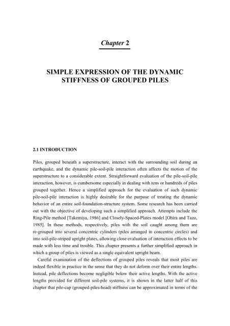
Chapter 2SIMPLE EXPRESSION OF THE DYNAMICSTIFFNESS OF GROUPED PILES2.1 INTRODUCTIONPiles, <strong>grouped</strong> beneath a superstructure, interact with <strong>the</strong> surrounding soil during anearthquake, and <strong>the</strong> <strong>dynamic</strong> pile-soil-pile interaction <strong>of</strong>ten affects <strong>the</strong> motion <strong>of</strong> <strong>the</strong>superstructure to a considerable extent. Straightforward evaluation <strong>of</strong> <strong>the</strong> pile-soil-pileinteraction, however, is cumbersome especially in dealing with tens or hundreds <strong>of</strong> <strong>piles</strong><strong>grouped</strong> toge<strong>the</strong>r. Hence a simplified approach for <strong>the</strong> evaluation <strong>of</strong> such <strong>dynamic</strong>pile-soil-pile interaction is highly desirable for <strong>the</strong> purpose <strong>of</strong> treating <strong>the</strong> <strong>dynamic</strong>behavior <strong>of</strong> an entire soil-foundation-structure system. Some research has been carriedout with <strong>the</strong> objective <strong>of</strong> developing such a simplified approach. Attempts include <strong>the</strong>Ring-Pile method [Takemiya, 1986] and Closely-Spaced-Plates model [Ohira and Tazo,1985]. In <strong>the</strong>se methods, respectively, <strong>piles</strong> with <strong>the</strong> soil caught among <strong>the</strong>m arere-<strong>grouped</strong> into several concentric cylinders (<strong>piles</strong> arranged in concentric circles) andinto soil-pile-striped upright plates, allowing close evaluation <strong>of</strong> interaction effects to bemade with less time and trouble. This chapter presents a fur<strong>the</strong>r simplified approach inwhich a group <strong>of</strong> <strong>piles</strong> is viewed as a single equivalent upright beam.Careful examination <strong>of</strong> <strong>the</strong> deflections <strong>of</strong> <strong>grouped</strong> <strong>piles</strong> reveals that most <strong>piles</strong> areindeed flexible in practice in <strong>the</strong> sense that <strong>the</strong>y do not deform over <strong>the</strong>ir entire lengths.Instead, pile deflections become negligible below <strong>the</strong>ir active lengths. With <strong>the</strong> activelengths provided for different soil-pile systems, it is shown in <strong>the</strong> latter half <strong>of</strong> thischapter that pile-cap (<strong>grouped</strong>-<strong>piles</strong>-head) <strong>stiffness</strong> can be approximated in terms <strong>of</strong> <strong>the</strong>
14 SIMPLE EXPRESSIONS OF THE DYNAMIC STIFFNESS OF GROUPED PILESmass, damping and <strong>stiffness</strong> parameters; <strong>the</strong> parameters are invariant <strong>of</strong> frequency andare dependent only on <strong>the</strong> mechanical properties <strong>of</strong> soil and pile. The method presentedin this report requires real-time manipulation <strong>of</strong> soil-structure interaction parameters inaccordance with <strong>the</strong> development <strong>of</strong> non-linear features <strong>of</strong> soils and <strong>piles</strong>. The present<strong>simple</strong> <strong>expression</strong> <strong>of</strong> pile-cap <strong>stiffness</strong>, thus proves to be useful despite <strong>the</strong> availability<strong>of</strong> efficient numerical programs for analyzing pile-soil-pile interaction.2.2 EQUIVALENT SINGLE UPRIGHT BEAMIn discussing <strong>the</strong> equivalent upright beam, straightforward evaluation <strong>of</strong> pile-soil-pileinteraction is first necessary to provide rigorous solutions. Based on <strong>the</strong> numericalscheme presented by Tajimi and Shimomura [Thin-Layered Method, 1976] that allowssoil-embedded foundation interaction effects to be rigorously evaluated, a numericalprogram “TLEM”(Ver. 1.1) has been developed for soil-pile group interaction analyses[Konagai, 1998d]. The Thin-Layered Element Method is a method for describing soilstrata ra<strong>the</strong>r than for foundations. In this method, a soil deposit is treated as an infinitestratified medium with <strong>the</strong> inclusion <strong>of</strong> a cylindrical hollow in which <strong>the</strong> foundation isfitted. The <strong>piles</strong> are assumed to be upright Timoshenko or Beronoulli-Euler beams. Theevaluation <strong>of</strong> pile-soil-pile interaction effects in this program is based on <strong>the</strong>superposition method that was originally proposed by Poulos [1968, 1971]. In thisapproximation, only two <strong>piles</strong> are considered in <strong>the</strong> formulation <strong>of</strong> a global flexibilitymatrix, and o<strong>the</strong>r <strong>piles</strong>’ effects on <strong>the</strong>se two <strong>piles</strong> are totally ignored (Figure 2.1).Kanya and Kausel [1982] have shown that <strong>the</strong> superposition scheme gives reasonableresults not only for static loads but for <strong>dynamic</strong> loads as well.active pilexθs d = 2r 0passive pileyFigure 2.1 Active and passive <strong>piles</strong>
SIMPLE EXPRESSIONS OF THE DYNAMIC STIFFNESS OF GROUPED PILES 15In contrast to <strong>the</strong> above approach, <strong>the</strong> present single upright beam is a composite <strong>of</strong>n <strong>piles</strong> and <strong>the</strong> soil caught among <strong>the</strong>m embedded in a horizontally stratified infinitepsoil deposit with material damping <strong>of</strong> <strong>the</strong> frequency-independent hysteretic type (Figure2.2). Following <strong>the</strong> TLEM assumption, <strong>the</strong> soil deposit overlying its rigid bedrock2π R 0, <strong>of</strong> thisshould include a cylindrical hollow <strong>of</strong> radius R 0. The cross-section,hollow is assumed to be identical to <strong>the</strong> beam’s cross-sectionAGenclosed with <strong>the</strong>broken line circumscribing <strong>the</strong> outermost <strong>piles</strong> in <strong>the</strong> group (Figure 2.2a). The motion<strong>of</strong> <strong>the</strong> hollow is assumed to be compatible with that <strong>of</strong> <strong>the</strong> beam. The soil-pilecomposite toge<strong>the</strong>r with its exterior soil is divided into n L horizontal slices as shownin Figure 2.2. The following assumptions are adopted to derive <strong>the</strong> <strong>stiffness</strong> matrix <strong>of</strong><strong>the</strong> equivalent single beam:(1) Pile elements within a horizontal soil slice are all deformed at once keeping <strong>the</strong>irintervals constant, and <strong>the</strong> soil caught among <strong>the</strong> <strong>piles</strong> moves in a body with <strong>the</strong><strong>piles</strong>.(2) Frictional effects due to bending <strong>of</strong> <strong>piles</strong> (external moments on each individual pilefrom soil) are ignored.(3) The top ends <strong>of</strong> <strong>piles</strong> are fixed to a rigid cap.(4) All upper or lower ends <strong>of</strong> <strong>the</strong> sliced pile elements arranged on <strong>the</strong> cut-end <strong>of</strong> a soilslice remain on one plane (Note this assumption does not necessarily mean thateach pile’s cross-section remains in parallel with this plane. See Figure 2.2b).centroidA gjR 0w 1u jcentroidR 0w jn Lh jn p <strong>piles</strong>(a) soil-<strong>grouped</strong> <strong>piles</strong> systemremain on one plane(b) sliced elementsFigure 2.2 Assumptions for evaluation <strong>of</strong> equivalent single beam
16 SIMPLE EXPRESSIONS OF THE DYNAMIC STIFFNESS OF GROUPED PILESWith assumptions (1) and (4), <strong>the</strong>re are only two degrees <strong>of</strong> freedom for each cut-end <strong>of</strong>all slices <strong>of</strong> <strong>the</strong> soil-pile composite, namely, sway and rocking motions respectivelyu ( { u u L } Tw ( = { w w L } T) (Figuredesignated as { }= ) and { }12u N L2.2b). The rocking motions are expressed in terms <strong>of</strong> <strong>the</strong> anti-symmetric vertical motion{ w } at <strong>the</strong> outermost edge ( r = R0) <strong>of</strong> <strong>the</strong> equivalent beam with respect to <strong>the</strong> beam’scentroid. In sway motions, all np<strong>piles</strong> are equally displaced (assumption (1)), causing<strong>the</strong> bending <strong>stiffness</strong>, EI , <strong>of</strong> <strong>the</strong> equivalent beam to be simply nptimes as large as<strong>the</strong> bending <strong>stiffness</strong> <strong>of</strong> an individual pile. Assumptions (3) and (4) imply that axialmotions <strong>of</strong> <strong>the</strong> <strong>piles</strong> control <strong>the</strong> overall anti-symmetric rocking motion <strong>of</strong> <strong>the</strong> equivalentbeam just as reinforcements in a concrete beam do. Therefore, ano<strong>the</strong>r bending <strong>stiffness</strong>parameter, EI G , is introduced to describe <strong>the</strong> rocking motion <strong>of</strong> <strong>the</strong> beam. This<strong>stiffness</strong> parameter EI G is evaluated following <strong>the</strong> same procedure as that used for <strong>the</strong>evaluation <strong>of</strong> bending <strong>stiffness</strong> <strong>of</strong> a reinforced concrete beam (See APPENDIX I).Lateral external forces { p x} and moments { M } are finally described in matrixnotation in terms <strong>of</strong> {} u and { w } as specified in Equation (A12) in APPENDIX I:12w NL−1−11st column <strong>of</strong>[ ][ ] [ ][ L][ D]/R ⎤0andL D L M⎥zeros for o<strong>the</strong>r columns ⎧ u ⎫⎥⎪⎪LLLLLLLL ⎥⎨L⎬−1−1[ D] [ L] /R and [ Q] with D added to <strong>the</strong> ⎥⎪⎪ ⎭⎡⎧ ⎫⎢⎪px ⎪⎢⎨L⎬ = ⎢ LLLLLLLL⎪ M ⎪ ⎢1st row <strong>of</strong>0⎪ ⎪ ⎢⎩R0⎭ ⎢⎣zeros for o<strong>the</strong>r rowswhere, [ L ], [ D ] and [ ]M1,1upper - left corner⎥⎩w⎥⎦(2.1)Q are assembled global matrices corresponding to <strong>the</strong>individual layer parameters <strong>of</strong> 1 / hj( hj= thickness <strong>of</strong> <strong>the</strong> j-th layer), h j/ EI andG 2EI / R0hj, respectively, (See Equations (A2), (A4) and (A10) in APPENDIX IQ , respectively).defining [ L ], [ D ] and [ ]“TLEM” has been upgraded for evaluation <strong>of</strong> <strong>the</strong> behaviors <strong>of</strong> an equivalent singlebeam (Ver. 1.2). Figure 2.3 shows pile cap <strong>stiffness</strong>es k xxfor sway motions <strong>of</strong> 2×2and 3×3 steel pile groups (Table 2.1) plotted as functions <strong>of</strong> frequency. The results for<strong>the</strong> equivalent beams are shown as open circles. Each pile group is embedded in <strong>the</strong>same homogeneous soil deposit (Table 2.2) equally divided into 20 slices. Downwarddips in <strong>the</strong>se plots <strong>of</strong> k xxoccur at essentially <strong>the</strong> resonance frequencies <strong>of</strong> <strong>the</strong> soilstratum for vertical shear wave propagation. As a whole, however, every real part <strong>of</strong> <strong>the</strong>pile cap <strong>stiffness</strong>es decreases slowly as <strong>the</strong> frequency increases, whereas its imaginarypart representing <strong>the</strong> damping <strong>of</strong> a soil-pile group system shows a general upward trendto <strong>the</strong> right. The curves for <strong>the</strong> equivalent single beams agree well with rigoroussolutions from “TLEM” (Ver. 1.1).
SIMPLE EXPRESSIONS OF THE DYNAMIC STIFFNESS OF GROUPED PILES 17Table 2.1 Parameters for steel <strong>piles</strong>E p (tf/m 2 ) ρ (t/m 3 ) r 0 (m) Thickness (m) Length (m)2.1×10 7 7 0.3 0.0089 20Table 2.2 Parameters for soilρ (t/m 3 ) v (m/s)T1.5 80 0.49ν4.02 2 <strong>piles</strong>d4.03 3 <strong>piles</strong>Impedance k xx(10 4 tf/m)rigorous solution3.0 s3.0equivalent beamreal part2.01.0imag. part0.00 2 4 6 8 10Frequency (Hz)Impedance k xx(10 4 tf/m)real part2.0s / d = 2.51.0imag. part0.00 2 4 6 8 10Frequency (Hz)Figure 2.3 Variations <strong>of</strong> <strong>stiffness</strong> parameters for sway motions <strong>of</strong> pile groupsAssumption (1) taken in this chapter to derive <strong>the</strong> <strong>stiffness</strong> matrix <strong>of</strong> <strong>the</strong>equivalent-upright beam (Equation (2.1)) implies that <strong>the</strong> spacing between <strong>piles</strong>, s,should be within a certain limit. To investigate this constraint on <strong>the</strong> spacing between<strong>piles</strong>, <strong>the</strong> results <strong>of</strong> <strong>the</strong> program “TLEM” (Ver. 1.2) were compared with <strong>the</strong> rigorousresults obtained from “TLEM” (Ver. 1.1). Here, hollow cylindrical steel <strong>piles</strong> (Table2.1) embedded in a homogeneous soil with <strong>the</strong> density ρ and <strong>the</strong> shear wave velocityvT(Table 2.2) were considered. The variations <strong>of</strong> <strong>the</strong> ratios between approximate andrigorous solutions with respect to normalized frequency ω s / vTare shown in Figure2.4 for three different values <strong>of</strong> spacing ( s/ d = 25, . s / d = 3. 33 and s/ d = 50). . Fora wide range <strong>of</strong> cases examined, “TLEM” (Ver. 1.2) is found to produce insignificanterror below a certain limit <strong>of</strong> spacing, s/ d < 3. Below this limit, however, it is noted
18 SIMPLE EXPRESSIONS OF THE DYNAMIC STIFFNESS OF GROUPED PILESthat <strong>the</strong> error can yet become significant as <strong>the</strong> non-dimensional frequency increasesbeyond a certain limit (See thick lines in Figure 2.4 for large number <strong>of</strong> <strong>piles</strong>).ffAn earthquake causes <strong>the</strong> free-field ground motion { u M w } Tin which verticaldisplacement vector { w f } can be ignored in many <strong>of</strong> <strong>the</strong> practical cases encountered.The <strong>piles</strong> in this soil deposit, however, will not follow <strong>the</strong> free-field deformation pattern.This deviation <strong>of</strong> <strong>the</strong> displacements from <strong>the</strong> free-field soil displacements is denoted byss{ w } Tf sf s{ u u w + w } Tu M . Equation (2.1) is also used to evaluate effective foundation input motion+ M . The effects <strong>of</strong> soil-embedded-foundation kinematicinteraction are portrayed in <strong>the</strong> form <strong>of</strong> two kinematic displacement factors in sway androcking motionsf sf s su uT = 1+1e,swayfu, w1+ w1w1Te, rocking= ≅(2.2a), (2.2b)ff1u1u1plotted as functions <strong>of</strong> frequency. In Equation (2.2b), <strong>the</strong> vertical component <strong>of</strong>ffree-field ground motion w 1is ignored.2 by 21.00.83 by 34 by 45 by 5|approx. solution||rigorous solution|0.6ω s / v T= 0.620.4s / d = 2.50.2s / d = 3.3s / d = 5.00.00.0 0.5 1.0nondimensional frequency (= ωs /v T)Figure 2.4Variation <strong>of</strong> ratios between approximate and rigoroussolutions with respect to normalized frequency ω s / vT
SIMPLE EXPRESSIONS OF THE DYNAMIC STIFFNESS OF GROUPED PILES 19Figure 2.5 shows <strong>the</strong> kinematic displacement factors <strong>of</strong> a 2×2 PC pile group plottedas functions <strong>of</strong> non-dimensional frequency ω s / vT(s/ d = 2 , See Tables 2.3 and 2.4),and <strong>the</strong>y are in good agreement with rigorous solutions by Fan et al. (1982).It is again to be remembered that <strong>the</strong> <strong>piles</strong> behaving in accordance with assumption(1) are completely equal with each o<strong>the</strong>r not only in <strong>the</strong>ir deformations but also inlengthwise distributions <strong>of</strong> internal force and moment. The <strong>dynamic</strong> pile-soil-pileinteraction effects are thus excluded. Even for a static loading, any discussion based on<strong>the</strong> assumption does not reflect <strong>the</strong> fact that outermost <strong>piles</strong> sustain heavier loads thanthose on inner <strong>piles</strong> (static pile-soil-pile interaction). Yet, <strong>the</strong> present single uprightbeam, as has been shown above, satisfactorily approximates <strong>the</strong> motions <strong>of</strong> a pile groupwith a reduced number <strong>of</strong> parameters. These parameters allow <strong>the</strong> <strong>stiffness</strong> parameters<strong>of</strong> a pile cap to be described in a fur<strong>the</strong>r simplified manner; a discussion <strong>of</strong> lateraltranslation follows in Section 2.3.Table 2.3 Parameters for <strong>piles</strong>EpIp (tf m2 ) ρ (t/m 3 ) r 0 (m) length (m)2.4×10 5 2.0 0.5 15Table 2.4 Parameters for surface soil depositρ (t/m 3 ) v (m/s) ν Thickness (m)T1.75 100 0.40 20kinematic displacement factorsT e, swayand T e, rocking1.51.00.50.0after Fan et al.sway (E p/E s= 1000)rocking (E p/E s= 1000)sway (E p/E s= 10000)rocking (E p/E s= 10000)rockingswayTLEM0.0 0.1 0.2 0.3 0.4 0.5normalized frequency (ω d/v T)Figure 2.5 Kinematic displacement factors <strong>of</strong> pile groups
20SIMPLE EXPRESSIONS OF THE DYNAMIC STIFFNESS OF GROUPED PILES2.3. ACTIVE PILE LENGTH AND PILE CAP STIFFNESS2.3.1 Active pile lengthIn practice, most laterally loaded <strong>piles</strong> are ‘flexible’ in <strong>the</strong> sense that <strong>the</strong>y do not deformover <strong>the</strong>ir entire length L. Instead, pile deflections become negligible below an activelength L (Figure 2.6). This length depends on how stiff <strong>the</strong> pile is in comparisonawith <strong>the</strong> surrounding soil. In engineering practice, Chang’s formula is widely used; inthis a pile is supported by discrete soil springs K hd , and <strong>the</strong> characteristic parameter isintroduced as β =4K hd / 4EIwith Khdesignating <strong>the</strong> coefficient <strong>of</strong> subgradereaction and d <strong>the</strong> pile diameter. The length given by 1 / β is thus directly relevant to<strong>the</strong> active pile length La. When a soil is treated as an elastic continuum, however, it isto be recognized that Khis not an inherent constant in <strong>the</strong> soil, but ra<strong>the</strong>r dependenton d . In addition, <strong>the</strong> active pile length is more rationally evaluated by replacing K hdwith <strong>the</strong> shear modulus <strong>of</strong> soil µ . Some formulas for ra<strong>the</strong>r extreme soil pr<strong>of</strong>iles havebeen presented by Randolf(1981), Velez (1983) and Gazetas (1983), and in general, L ais closely related to <strong>the</strong> following parameter L 0:EIL0= 4(2.3)µwhere, EI = bending <strong>stiffness</strong> <strong>of</strong> <strong>the</strong> pile, and µ = shear modulus <strong>of</strong> soil(representative value). The active length L ais thus given as:L a= α L 0 0(2.4)with <strong>the</strong> parameter α0reflecting different soil pr<strong>of</strong>iles. For an nppile group, EI inEquation (2.3) will presumably be replaced with EI ( = n E I ) specified byEquation (A5) in APPENDIX I.R 0pppL aFigure 2.6Active length <strong>of</strong> pile
SIMPLE EXPRESSIONS OF THE DYNAMIC STIFFNESS OF GROUPED PILES 212.3.2 Pile cap <strong>stiffness</strong>It is assumed that only <strong>the</strong> soil above <strong>the</strong> active pile length, L a, is deformed asshown in Figure 2.7a. The upper soil is <strong>the</strong>n divided into vertical soil columns. Given<strong>the</strong> prescribed vibration mode ψ z / L ) that satisfies ψ ( 0) = 1 and ψ ( 1) = 0 , <strong>the</strong>se(acolumns can be replaced with <strong>simple</strong>-damped oscillators. Reducing <strong>the</strong> cross-section <strong>of</strong>each soil column, <strong>the</strong> soil deposit above L ais modeled by an infinite plane supportedby Winkler-type springs (Figure 2.7b). Lame’s constants λ p, µ p( µ p= shearmodulus) and mass density ρ p<strong>of</strong> <strong>the</strong> soil plane and Winkler-type spring constant k pfor <strong>the</strong> model are expressed in terms <strong>of</strong> ψ as:L a22λ = λ( z)( ψ ( z / L ))dz , µ = µ( z)( ψ ( z / L ))dz , ρ = ρ( z)( ψ ( z / L ))p∫0L aapL a2∫0⎛ dψ( z / La)and ∫ ⎟ ⎞kp= µ ( z)⎜dz(2.5a)-(2.5d)⎝ d z0⎠A frequency parameter, ω 0, is introduced herein as:ω = k p0(2.6)ρpFor a homogeneous soil, parameters λ p, µ pand ρ pin Equations (2.5a)-(2.5c) arerewritten asλp= λα 1L a, µp= µα 1Laand ρp= ρα 1La(2.7a)-(2.7c)12with α1 = ∫( ψ1( ζ ))d ζ .0Even for inhomogeneous soils too, similar <strong>expression</strong>s may be derived with λ , µ , andρ interpreted as representative values <strong>of</strong> λ( z ), µ( z ) and ρ( z ), and <strong>the</strong> parameterα1portraying different soil pr<strong>of</strong>iles.apL a∫0a2dzψR 0λ µ ρk pppm gpL ak gz(a) Vertically sliced soil above L a(b) Equivalent modelFigure 2.7 Soil deformation
22SIMPLE EXPRESSIONS OF THE DYNAMIC STIFFNESS OF GROUPED PILESThe <strong>expression</strong> <strong>of</strong> soil <strong>stiffness</strong>, k s, for <strong>the</strong> lateral motion <strong>of</strong> a massless bodyembedded in <strong>the</strong> soil plane in Figure 2.7b is completely identical to that given in Novaket al. [1978] regardless <strong>of</strong> <strong>the</strong> presence <strong>of</strong> Winkler-type springs kp, i.e.:2 4K1(b0) K1(a0) + a0K1(b0) K0( a0) + b0K0( b0) K1(a0)ks= πµpa0(2.8)b0K0( b0) K1(a0) + a0K1(b0) K0( a0) + b0a0K0( b0) K0( a0)where K 0and K 1are modified Bessel functions <strong>of</strong> <strong>the</strong> first and second order,respectively. Both a 0and b 0are normalized circular frequencies. As shown inAPPENDIX II, <strong>the</strong> only difference from Novak’s solution, owing to <strong>the</strong> presence <strong>of</strong>Winkler-type springs k pappears as an inclusion <strong>of</strong> <strong>the</strong> frequency parameter ω 0ina 0and b 0as:0R0a0= ω 0R0η , b0= ω ωη with η = − ⎛ v Tv L⎝ ⎜ ⎞1 ⎟(2.9a)-(2.9c)ω0 ⎠in which ω is <strong>the</strong> circular frequency, and= µ / ρ (= transverse wave velocity in <strong>the</strong> plane) (2.9d)vT pppvL p= ( λp+ 2µp) / ρp(= longitudinal wave velocity in <strong>the</strong> plane) (2.9e).Since a0and b 0are respectively functions <strong>of</strong> vT pand vL p, Equation (2.8) is in turna function <strong>of</strong> <strong>the</strong> Poisson’s ratio ν . The <strong>expression</strong> <strong>of</strong> Equation (2.8) for a Poisson’sratio equal to 0.5 is obtained by taking a limit as ν → 0. 5 in Equation (2.8), i.e.:* 2k s = 2S + msω (2.10)where m s( = ρπ p R 2 0 ) is <strong>the</strong> soil mass <strong>of</strong> <strong>the</strong> same volume as <strong>the</strong> cylindrical hollow in<strong>the</strong> soil plane, andaK aS* 0 1 ( 0= 2πµ )(2.11)K ( a )0 02Table 2.5 Values <strong>of</strong> ξ kand ξ mPoisson’s ratio,νξ kξ m0.50 2.000 1.00000.47 1.831 0.53360.45 1.741 0.37400.43 1.667 0.26280.40 1.580 0.14280.35 1.476 0.03520.25 1.351 00.20 1.311 00.10 1.252 00.00 1.213 0
SIMPLE EXPRESSIONS OF THE DYNAMIC STIFFNESS OF GROUPED PILES 23It is found that <strong>the</strong> <strong>stiffness</strong> k sfor any Poisson’s ratio o<strong>the</strong>r than 0.5 can beapproximately expressed in <strong>the</strong> same form as Equation (2.10) but with a smallmodification [Nogami and Konagai, 1986], i.e.:* 2ks = ξk( ν) ⋅ S + ξm( ν)⋅msω(12)where, ξk( ν) and ξ m( ν) are functions dependent only on Poisson’s ratio ν . Thevalues ξk( ν) and ξ m( ν) are given in Table 2.5.Konagai et al. [1992, 1998b] have shown that assuming plane stress condition over<strong>the</strong> entire extent <strong>of</strong> <strong>the</strong> soil plane allows k sto approximate closely <strong>the</strong> rigoroussolution <strong>of</strong> <strong>the</strong> soil <strong>stiffness</strong>, and thus, Poisson’s ratio ν in Equation (2.12) must bereplaced with ν * for a plane-stress medium, which is expressed as:*λ*pν = (2.13)*2( λ + µ )pp2λ µwhere, λ* p pp =(2.14)λ p + µ pIt is noted that ν * ranges from 0 to 1/3, and thus, ξm ( *ν ) in Equation (2.12) iscompletely equal to zero. Equation (2.12) is <strong>the</strong>n rewritten as;* *ks= ξk( ν ) ⋅S(2.15)The function K1( a0) / K0( a0) is approximated by 1+ 0.4 / a0, when <strong>the</strong> absolute value<strong>of</strong> a0is larger than 0.01 [Konagai and Nogami, 1998a]. This simplification leads to:* aK 0 1( a0)*k s = 2πµ pξk( ν ) ≅2πµ pξk( ν ) ⋅ a0( 1+04 . / a0)(2.16)K0( a0)Two limiting cases <strong>of</strong> ω → 0 and ω →∞ are addressed herein. For <strong>the</strong> static case( ω ≅ 0 ), η <strong>of</strong> Equation (2.9c) approaches 1. Replacing ω 0and v in Equation(2.9a) with those specified in Equations (2.6) and (2.9d), respectively, non-dimensionalfrequency a 0in <strong>the</strong> static case is expressed as:ak= (2.17)p0R 0µpSubstituting into Equation (2.17) Equations (2.5d) and (2.5b) which specify kpandµp, respectively, Equation (2.17) is rewritten as:α2R0a0= (2.18)α1L a12⎛ dψ( ζ ) ⎞where, α2= ∫ ⎜ ⎟ dζwith ζ = z / La0 ⎝ dζ⎠Equation (2.16) is thus simply written as:T p
24SIMPLE EXPRESSIONS OF THE DYNAMIC STIFFNESS OF GROUPED PILES⎛α⎞ ⎛⎞2R0R0k ≅ ⎜ +⎟ =⎜ +⎟s2πξkα1µLa0.4 µ La2πξkα20. 8πξkα1(2.19)⎝ α1La⎠ ⎝ La⎠For <strong>the</strong> <strong>dynamic</strong> case (ω →∞), non-dimensional frequency a 0converges on:ω R0a0= i = ia(2.20)vT pEquation (2.16) is thus approximated by:k ≅ L i ⋅ 2πξα ⋅ a + 0. πξ α(2.21)s( )µa k 18k1From Equations (2.19) and (2.21), soil <strong>stiffness</strong> will presumably be approximated as:⎧⎛R⎫0⎞k ⎨⎜⎟s≅ µ La2πξkα2+ 0.8πξkα1+ i ⋅ 2πξkα1⋅ a⎬(2.22)⎩⎝La⎠⎭Even without <strong>the</strong> soil above <strong>the</strong> active pile length, <strong>the</strong> pile group exhibits its own<strong>stiffness</strong>, k (Figure 2.7b), which is described as:kg4EIp µ L0α3gα3= α3 3= µ L3 3 0LaLaα0122≅ (2.23)⎛ d ψ ( ζ )where, ∫ ⎟ ⎞α3=⎜ dζ20 ⎝ dζ⎠Both ksand k gsustain <strong>the</strong> massamong <strong>the</strong> <strong>piles</strong>. This massmgLa02 20ψ z)mg<strong>of</strong> <strong>the</strong> embedded pile group with soil caughtmgis approximated by:20≅ ∫ ρ πR( dz = ρ πRL α(2.24)ssaTherefore <strong>the</strong> overall <strong>stiffness</strong> k xx<strong>of</strong> <strong>the</strong> pile cap for sway motion is given as:kxx = ks + kg −mgω 2 (2.25)From Equations (2.22), (2.23) and (2.24), Equation (2.25) is rewritten as:⎡⎪⎧R ⎛⎞⎪⎫⎤0α⎢⎨⎜32k⎟xx≅ µ La2πξkα2+⎬ + ⋅ ⋅ − ⋅ ⎥⎢0.8πξkα1+3i 2πξkα1a πα1a (2.26)⎣⎪⎩La⎝ α0 ⎠⎪⎭⎥⎦Substituting Equation (2.3) into Equation (2.26), one obtains:⎡⎪⎧R ⎛⎞⎪⎫⎤0α⎢⎨⎜32k⎟xx≅ µ L0 2πξkα2+⎬ + ⋅ ⋅ − ⋅ ⎥⎢0.8πξkα0α1+2i 2πξkα0α1a πα0α1a (2.27)⎣⎪⎩L0⎝α0 ⎠⎪⎭⎥⎦It is now obvious that k xxin Equation (2.27) has <strong>the</strong> following <strong>simple</strong> form withfrequency-independent <strong>stiffness</strong> k 0, and damping and mass parameters c 0and m 0respectively:2≅ k + i ⋅ c ⋅ a − m ⋅(2.28)where,k xx0 00a1
SIMPLE EXPRESSIONS OF THE DYNAMIC STIFFNESS OF GROUPED PILES 25k0R0c0m0= c1+ c2, = c3andµ L0L0µ L0µ L0= c4(2.29a)-(2.29c)with c1= 2πξ kα2,α3c2= 0. 8πξ kα0α1+2α0, c3= 2πξ kα0α1and c4= πα0α1.(2.30a)-(2.30d)The above equations show some important features <strong>of</strong> <strong>the</strong> pile cap <strong>stiffness</strong>. Among <strong>the</strong>parameters specified in <strong>the</strong> above equations, c1, c2, c3and c 4are dependent on <strong>the</strong>shape function ψ ( ζ ), which may not differ drastically in different soil-pile systems aslong as <strong>piles</strong> exhibit a flexible nature, and k / L 0µ0alone includes a term proportionalto 0 0. Equation (2.28) was derived with <strong>the</strong> intention <strong>of</strong> showing what could be <strong>the</strong>most important key parameters that determine . The assumption taken to derive <strong>the</strong>equation is good enough for this purpose, but certainly is an oversimplification <strong>of</strong> reality.Since soils below active pile lengths are not allowed to deform at all, <strong>the</strong> assumption isliable to lead to overestimation <strong>of</strong> <strong>the</strong> <strong>stiffness</strong> parameter k 0and underestimation <strong>of</strong><strong>the</strong> damping parameter c0. Therefore, parameters c 1, c2, c3and c 4were obtainednot directly from Equations (2.30a)-(2.30d), but in such a way that <strong>the</strong> overall errorwould be minimized for <strong>the</strong> variety <strong>of</strong> soils and pile parameters examined. Theparameters that have been considered are: 1) pile parameters such as group-pile <strong>stiffness</strong>,EI ( = npEpIp), and active pile length ratio, L0 / L; and 2) soil parameters includingshear modulus µ and material damping D . In this discussion, only a homogeneoussoil pr<strong>of</strong>ile with a square arrangement <strong>of</strong> <strong>piles</strong> is considered. The best fit <strong>of</strong> <strong>the</strong> valuesfrom Equation (2.28) to rigorous solutions <strong>of</strong> k xxwas obtained by setting c 1, c 2, c 3and c 4at 2π , π /2, 2π and π /4, respectively. Some representative cases areshown in Figures 2.8a-2.8f.The present <strong>simple</strong> <strong>expression</strong> <strong>of</strong> k xx(Equation (2.28)) allows <strong>the</strong> effects <strong>of</strong> overallsite non-linearity to be reflected by simply replacing <strong>the</strong> shear modulus <strong>of</strong> <strong>the</strong> intact soil,µ , with <strong>the</strong> complex modulus, µ'( 1 + iD ); this describes equivalent-linear features <strong>of</strong><strong>the</strong> soil experiencing <strong>dynamic</strong> loading, and is obtained from shear-modulus-reductionand damping ratio curves <strong>of</strong> <strong>the</strong> soil. This manipulation, however, causes <strong>the</strong> <strong>stiffness</strong>and damping parameters k 0and c 0in Equations (2.29a) and (2.29b) to be slightlydependent on frequency as:k0⎛ R0π ⎞= ⎜2π+ ⎟ −2πD⋅ a(2.31a)µ ' L ⎝ L 2 ⎠00c0⎛ R0π π 2⎞= 2π+ ⎜2π+ − a ⎟ D(2.31b)µ ' L0⎝ L02 4 ⎠When <strong>the</strong> effect <strong>of</strong> D cannot be ignored in Equations (2.31a) and (2.31b), appropriatekxx
26SIMPLE EXPRESSIONS OF THE DYNAMIC STIFFNESS OF GROUPED PILESvalues <strong>of</strong> k 0and c 0must be determined taking into account <strong>the</strong> most probablepredominant frequency a in <strong>the</strong> soil-structure interaction reality. Figures 2.8a-2.8bshow that introducing <strong>the</strong> complex shear modulus <strong>of</strong> soil, <strong>the</strong> effect <strong>of</strong> material dampinghas properly been taken into account.The downward dips in <strong>the</strong>se non-dimensional plots <strong>of</strong> rigorous variations <strong>of</strong> k xxvs.frequency occur at essentially <strong>the</strong> resonance frequencies <strong>of</strong> <strong>the</strong> soil stratum for verticalshear wave propagation. Thus <strong>the</strong> results from ‘TLEM’ analyses with a perfectly rigidbase laid under <strong>the</strong> soil stratum correspond to cases where this effect is mostpronounced. It is <strong>the</strong>refore more likely that <strong>the</strong> solutions adhere along <strong>the</strong> ridges <strong>of</strong><strong>the</strong>se plots as <strong>the</strong> bases become more flexible. As can be seen from Figure 2.8c,Equation (2.28) underestimates slightly <strong>the</strong> real part <strong>of</strong> <strong>stiffness</strong>, and overestimates itsimaginary part for lower values <strong>of</strong> shear modulus <strong>of</strong> soil.From <strong>the</strong> study <strong>of</strong> a wide range <strong>of</strong> pile parameters (viz. number <strong>of</strong> <strong>piles</strong>, diameter <strong>of</strong>individual <strong>piles</strong> and length <strong>of</strong> <strong>piles</strong>), it was found that Equation (2.28) is validirrespective <strong>of</strong> pile and soil parameters as long as <strong>the</strong> active-pile-length ratio, L0 / L , iswithin a certain limit. Beyond this limit, <strong>the</strong> behavior <strong>of</strong> <strong>piles</strong> deviates from <strong>the</strong>‘flexible’ nature. Figures 2.8d-2.8f show this trend <strong>of</strong> <strong>the</strong> deviation <strong>of</strong> Equation (2.28)from <strong>the</strong> results <strong>of</strong> “TLEM” (Ver. 1.2) as <strong>the</strong> ratio L0 / L increases. In <strong>the</strong>se figures,L0 / L are changed by arbitrarily changing <strong>the</strong> number <strong>of</strong> <strong>piles</strong> and/or diameter <strong>of</strong>individual <strong>piles</strong>. These figures show that <strong>the</strong> allowable limit <strong>of</strong> L0 / L is 0.3 or less.A similar <strong>expression</strong> must also be derived for <strong>the</strong> <strong>dynamic</strong> <strong>stiffness</strong> <strong>of</strong> <strong>grouped</strong> <strong>piles</strong>in rocking motion and for <strong>the</strong> coupled <strong>stiffness</strong> between lateral sway and rockingmotions. In this extension also, active pile length, if rationally estimated, would allow<strong>the</strong> pile-cap <strong>stiffness</strong> to be approximately described in a similar manner. Fur<strong>the</strong>r detailedstudy on this point will be addressed in a later publication.
SIMPLE EXPRESSIONS OF THE DYNAMIC STIFFNESS OF GROUPED PILES 27non-dimensional <strong>stiffness</strong>, k xx/(µL 0)n p=4, d=0.5m, L=10m, µ = 30000 tf/m 2 (v T= 414 m/s)2015105equivalent beam (TLEM)equation (28)real partimaginary partL 0/L= 0.10s/d= 4.1900 1 2 3non-dimensional frequency, ω R /v 0 TFigure 2.8a Variation <strong>of</strong> stifness for sway motion <strong>of</strong> pile cap(D = 0.05)non-dimensional <strong>stiffness</strong>, k xx/(µL 0)n p=4, d=0.5m, L=10m, µ = 30000 tf/m 2 ((v T)= 414 m/s)2015105equivalent beam (TLEM)equation (28)real partimaginary partL 0/L = 0.10s/d = 4.1900 1 2 3non-dimensional frequency, ω R 0 /v TFigure 2.8b Variation <strong>of</strong> <strong>stiffness</strong> for sway motion <strong>of</strong> pile cap(D = 0.20)
28SIMPLE EXPRESSIONS OF THE DYNAMIC STIFFNESS OF GROUPED PILESnon-dimensional <strong>stiffness</strong>, k xx/(µL 0)15105real partn p=4, d=0.5m, L=20mequivalent beam (TLEM)equation (28)imaginary partL 0/L = 0.10s/d = 4.19D = 0.0500.0 0.5 1.0 1.5non-dimensional frequency, ω R 0 /v TFigure 2.8c Variation <strong>of</strong> <strong>stiffness</strong> for sway motion <strong>of</strong> pile cap(µ = 1875 tf/m 2 , v T= 103.5 m/s)n p=4, d=0.5m, L=10m, µ = 30000 tf/m 2 (v T= 414 m/s)non-dimensional <strong>stiffness</strong>, k xx/µ L 02015105equivalent beam (TLEM)equation (28)real partimaginary partD= 0.10s/d= 4.1900 1 2 3non-dimensional frequency, ω R 0/v TFigure 2.8d Variation <strong>of</strong> <strong>stiffness</strong> for sway motion <strong>of</strong> pile cap(L 0/L = 0.10)
SIMPLE EXPRESSIONS OF THE DYNAMIC STIFFNESS OF GROUPED PILES 29n p=25, d=1m, L=10m, µ = 30000 tf/m 2 (v T= 414 m/s)non-dimensional frequency, k xx/(µL 0)40200-20imaginary partequivalent beam (TLEM)equation (28)D = 0.10s/d = 1.48137real part-400 2 4 6 8non-dimensional frequency, ω R 0 /v TFigure 2.8e Variation <strong>of</strong> <strong>stiffness</strong> for sway motion <strong>of</strong> pile cap(L 0/L = 0.31)n p=4, d=2m, L=10m, µ = 30000 tf/m 2 (v T= 414 m/s)non-dimensional frequency, k xx/(µL 0)80400-40imaginary partequivalent beam (TLEM)equation (28)D = 0.10s/d = 4.19real part-800 2 4 6 8 10 12non-dimensional frequency, ω R /v 0 TFigure 2.8f Variation <strong>of</strong> <strong>stiffness</strong> for sway motion <strong>of</strong> pile cap(L 0/L = 0.40)
30SIMPLE EXPRESSIONS OF THE DYNAMIC STIFFNESS OF GROUPED PILES2.4. SUMMARYPiles <strong>grouped</strong> beneath a superstructure can be viewed as a single equivalent uprightbeam when <strong>the</strong> <strong>piles</strong> are closely spaced. The <strong>stiffness</strong> matrix presented herein (Equation(2.1)) yields close approximations <strong>of</strong> both <strong>dynamic</strong> pile-cap <strong>stiffness</strong> and kinematicdisplacement factors. This idealization <strong>of</strong> <strong>grouped</strong> <strong>piles</strong> as a single equivalent uprightbeam and <strong>the</strong> concept <strong>of</strong> <strong>the</strong> active pile length have facilitated <strong>the</strong> derivation <strong>of</strong> a <strong>simple</strong><strong>expression</strong> <strong>of</strong> pile-cap <strong>stiffness</strong> in terms <strong>of</strong> frequency-independent mass, damping and<strong>stiffness</strong> parameters (Equations (2.29a)-(2.29c)). This <strong>expression</strong> is valid irrespective <strong>of</strong>pile and soil parameters as long as <strong>the</strong> pile group exhibits a “flexible” nature with itsactive-pile-length ratio, L0 / L, kept less than 0.3. The present <strong>simple</strong> <strong>expression</strong> <strong>of</strong>pile-cap <strong>stiffness</strong> also allows <strong>the</strong> effects <strong>of</strong> overall site non-linearity to be reflected bysimply replacing <strong>the</strong> shear modulus <strong>of</strong> <strong>the</strong> intact soil, µ , with <strong>the</strong> complex modulus,µ'( 1+ iD ) , which describes equivalent-linear features <strong>of</strong> <strong>the</strong> soil experiencing <strong>the</strong>seismic motion.A similar <strong>expression</strong> must also be derived for <strong>the</strong> <strong>dynamic</strong> <strong>stiffness</strong> <strong>of</strong> <strong>grouped</strong> <strong>piles</strong> inrocking motion and for <strong>the</strong> coupled <strong>stiffness</strong> between lateral sway and rocking motions.Moreover, <strong>the</strong>re is fur<strong>the</strong>r scope to extend this study for inhomogeneous soil-pr<strong>of</strong>ile and<strong>the</strong> local non-linearity <strong>of</strong> soil that develops in <strong>the</strong> vicinity <strong>of</strong> <strong>piles</strong>. In <strong>the</strong>se extensionsalso, active pile length, if rationally estimated, would allow pile-cap <strong>stiffness</strong> to beapproximately described in a similar manner. This will be discussed in futurepublications.REFERENCESFan, K., Gazetas, G., Kanya, A., Kausel, E. and Ahmad, S. [1991] “Kinematic SeismicResponse <strong>of</strong> Single Piles and Pile Groups,” Jour., Geotechnical Engineering, ASCE,117(12), 1860-1879.Gazetas, G. and Dobry, R. [1984] “Horizontal Response <strong>of</strong> Piles in Layered Soils,” Journal <strong>of</strong>Geotechnical Engineering, ASCE, 110(1), 20-40.Kanya, A. and E. Kausel [1982] “Dynamic Stiffness and Seismic Response <strong>of</strong> Pile Groups,”NSF report, NSF/CEE-82023.Konagai, K. and Maehara, M. [1992] “Study on Hypo<strong>the</strong>ses for Simple Numerical Evaluation<strong>of</strong> Soil-Embedded Structure Interaction,” Bull., Earthquake Resistant Structure ResearchCenter, 25, 39-60.Konagai, K. and T. Nogami [1998a] “Analog circuit to simulate <strong>dynamic</strong> soil-structureinteraction in shake table test,” International Journal <strong>of</strong> Soil Dynamics and EarthquakeEngineering, 17(5), 279-287.Konagai, K., A. Mikami and T. Nogami [1998b] “Simulation <strong>of</strong> Soil-Structure InteractionEffects in Shaking Table Tests,” Geotechnical Earthquake Engineering and Soil Dynamics
SIMPLE EXPRESSIONS OF THE DYNAMIC STIFFNESS OF GROUPED PILES 311998, Seattle, Geotechnical Special Technical Publication, ASCE, 75(1), 482-493.Konagai, K., Nogami, T., Katsukawa, T., Suzuki, T. and Mikami, A. [1998c] “Real TimeControl <strong>of</strong> Shaking Table for Soil-Structure Interaction Simulation,” Jour. <strong>of</strong> StructuralMechanics and Earthquake Engineering, JSCE, 598/I-44, 203-210.Konagai, K. [1998d] “Guide to TLEM,” program manual No. 5, Konagai Lab., IIS, Univ. <strong>of</strong>Tokyo.Nogami, T. and Konagai, K. [1988] “Time Domain Flexual Response <strong>of</strong> Dynamically LoadedSingle Piles,” Journal <strong>of</strong> Engineering Mechanics, ASCE, 114(9), 1512-1525.Novak, M., Nogami, T. and Aboul-Ella, F. [1978] “Dynamic Soil Reactions for Plane StrainCase,” Proc., ASCE, 104(EM4), 953-959.Ohira, A., Tazo, T, Nakahi, S. and Shimizu, K. [1985] “Study <strong>of</strong> Dynamic Behavior <strong>of</strong> Piles inS<strong>of</strong>t Soils,” Journal <strong>of</strong> Structural Engineering / Earthquake Engineering, 362/I-4, 417-426.Randolph, M. F. [1981] “Response <strong>of</strong> Flexible Piles to Lateral Loading,” Geotecnique, 31(2),247-259.Tajimi, H. and Y. Shimomura [1976] “Dynamic Analysis <strong>of</strong> Soil-Structure Interaction by <strong>the</strong>Thin Layered Element Method,” Transactions <strong>of</strong> <strong>the</strong> Architechtual Institute <strong>of</strong> Japan, 243,41-51.Takemiya, H. [1986] “Ring-Pile Analysis for a Grouped Pile Foundation Subjected to BaseMotion,” Structural Engineering/Earthquake Engineering, 3(1), 195s-202s.Velez, A., Gazetas, G., and Krishnan, R. [1983] “Lateral Dynamic Response <strong>of</strong> ConstrainedHead Piles,” Journal <strong>of</strong> Geotechnical Engineering, ASCE, 109(8).Poulos, H. G. [1968] “Analysis <strong>of</strong> <strong>the</strong> Settlement <strong>of</strong> Pile Groups,” Geotechnique, 18, 449-471Poulos, H. G. [1971] “Behavior <strong>of</strong> Laterally Loaded Piles,” Jour., Soil Mechanics andFoundation Division, ASCE, 97(SM5), 733-751.
32SIMPLE EXPRESSIONS OF THE DYNAMIC STIFFNESS OF GROUPED PILES