to download the Actaris CL231N Gas Pressure ... - Burnerparts
to download the Actaris CL231N Gas Pressure ... - Burnerparts
to download the Actaris CL231N Gas Pressure ... - Burnerparts
- No tags were found...

Create successful ePaper yourself
Turn your PDF publications into a flip-book with our unique Google optimized e-Paper software.
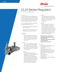
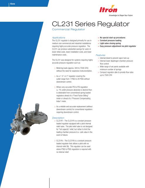
<strong>Gas</strong>CL231 Series Regula<strong>to</strong>rCommercial Regula<strong>to</strong>rApplicationsThe CL231 regula<strong>to</strong>r is designed primarily for use inmedium size commercial and industrial installationsrequiring highly accurate pressure regulation. TheCL231 can produce substantial savings for users inlower initial costs, lower installation costs, and lowermaintenance costs.The CL231 was designed for systems requiring highlyaccurate pressure regulation such as:> Metering loads (approx. 500 <strong>to</strong> 7500 CFH)without <strong>the</strong> need for expensive instrumentation.> As a 1 ½” or 2” regula<strong>to</strong>r covering <strong>the</strong>outlet range from 1 PSIG <strong>to</strong> 20 PSIG withoutdownstream control.> No special start-up procedures> Constant pressure loading> Light valve closing spring> Easy pressure adjustment via pilot regula<strong>to</strong>rFeatures> Internal bleed <strong>to</strong> prevent vapor lock-up> Internal lower diaphragm chamber pressureflow control> Wide range of set points available withminimum number of springs> Compact regula<strong>to</strong>r able <strong>to</strong> provide flow ratesup <strong>to</strong> 7500 CFH> Where very accurate PSI <strong>to</strong> PSI regulation(± 1% outlet pressure absolute) is desired thanis obtainable from conventional spring loadedregula<strong>to</strong>rs ahead of a “Fixed Fac<strong>to</strong>r Billing”meter or ahead of a “<strong>Pressure</strong> CompensatingIndex” meter.> As a reliable and accurate replacement (withoutdownstream control) for conventional regula<strong>to</strong>rsrequiring downstream control.Description> CL231R – The CL231R is a constant pressureloaded regula<strong>to</strong>r equipped with a pilot internalrelief valve. The pilot relief valve is not designedfor “full capacity” relief, but ra<strong>the</strong>r <strong>to</strong> limit <strong>the</strong>loading chamber pressure <strong>to</strong> a safe value in <strong>the</strong>event of failure.> <strong>CL231N</strong> – The <strong>CL231N</strong> is a constant pressureloaded regula<strong>to</strong>r that utilizes a pilot with nointernal relief (N). This regula<strong>to</strong>r can be usedwhere PSIG <strong>to</strong> PSIG regulation is required withno internal relief.
Shipping weight per boxFour regula<strong>to</strong>rsBox weight: 53 lbs.CL231 Dimensions (inches)Valve Body A B C D ENPT(all sizes)Flanged(all sizes)5-3/4 2-7/810 58 6-1/2 22 CL231 Constant Loaded Regula<strong>to</strong>r
Operational SchematicShown with N-type pilot.Note: Valve shown in closed position.CL231 Constant Loaded Regula<strong>to</strong>r 3
Itron takes pride in delivering American made products with <strong>the</strong> utmost concern for safety, quality, and cus<strong>to</strong>mer satisfaction.Construction materials:Closing springMusic wireValve body High tensile strength cast iron (ASTM A-126, Class A)OrificeBrass (ASTM B16, Alloy 360), aluminum - optionalValve seatBuna-N or silicone (for temperatures below -20°F)Valve stemPlated steel (Aluminum alloy 2011-T3)Lever pin Stainless steel (Type 303)Lever Zinc and dichromate plated steel (AISI C1010)Upper diaphragm plate Zinc and dichromate plated steel (14 gauge steel)Lower diaphragm plate Die cast aluminum (ASTM B-85 Alloy SC84A)DiaphragmBuna-N and nylonPilot vent screenStainless steel (16 mesh)Adjustment ferrule Die cast aluminum (ASTM CS43A)Seal capDie cast aluminum (ASTM CS43A)Diaphragm caseDie cast aluminum (ASTM B85-Alloy SC84A)Valve Body Sizes (inches)Inlet Outlet Screwed (NPT-thread) Flanged (ASA 125)1-1/4 1-1/4 X1-1/4 1-1/2 X1-1/4 2 X1-1/2 1-1/2 X1-1/2 2 X2 2 X X3 3 XX indicates <strong>the</strong> valve body is available in that configuration.CL231 Constant Loaded Regula<strong>to</strong>r 5
Correction fac<strong>to</strong>rs for non-natural gas applicationsThe CL231 may be used <strong>to</strong> control gases o<strong>the</strong>r than natural gas. To determine <strong>the</strong> capacity for gases o<strong>the</strong>r than natural gas, multiply<strong>the</strong> values within <strong>the</strong> capacity tables by a correction fac<strong>to</strong>r. The table below lists <strong>the</strong> correction fac<strong>to</strong>rs for some of <strong>the</strong> more commongases:<strong>Gas</strong> Type Specific Gravity Correction Fac<strong>to</strong>r (CF)Air 1.00 0.77Butane 2.01 0.55Carbon Dioxide (Dry) 1.52 0.63Carbon Monoxide (Dry) 0.97 0.79Natural <strong>Gas</strong> 0.60 1.00Nitrogen 0.97 0.79Propane 1.53 0.63Propane-Air-Mix 1.20 0.71To calculate <strong>the</strong> correction fac<strong>to</strong>r for gases not listed in <strong>the</strong> table above, use <strong>the</strong> gases’ specific gravity and insert it in <strong>the</strong> formulalisted below:Correction Fac<strong>to</strong>r (CF) =Where:SG 1 = Specific gravity of <strong>the</strong> gas in which <strong>the</strong> capacity is published.SG 2 = Specific gravity of <strong>the</strong> gas <strong>to</strong> be controlled.Wide Open Flow CalculationsFor wide-open orifice flow calculations use <strong>the</strong> following equations:For P 1/P 2 < 1.89 use: Q K P2( P1P2)For P 1/P 2 > 1.89 use:QKP12Where: P 1 = Absolute Inlet <strong>Pressure</strong> (PSIA) P 2 = Absolute Outlet <strong>Pressure</strong> (PSIA)Q = Flow Rate (scfh)K = Orifice Coefficient (scfh/PSI)6 CL231 Constant Loaded Regula<strong>to</strong>r
CL231 Capacity Table (Models R and N)*1% Absolute DroopTypical Capacity Info.Capacities in SCFH of 0.6 S.G. gas; base conditions of 14.7 PSIA and 60ºF.Orifice SizeManufacturer Itron InletType and model: CL231<strong>Pressure</strong>Regula<strong>to</strong>r(PSIG)Outlet<strong>Pressure</strong>(PSIG)1/4" 3/8" 1/2"Inlet size: 2" NPT 2 1 475 675 1100Outlet size: 2" NPT 3 1 675 1050 1750Spring color: Varies 2 475 750 1250Position 5 5 1 940 1650 26002 800 1550 2300101 1440 2700 43502 1400 2700 42005 1150 2100 30001 1850 3550 595015 2 1850 3550 59505 1750 3200 520010 1100 2100 29501 2200 4300 7250202 2200 4300 72505 2100 4100 670010 1850 3450 570015 1100 1650 26001 2800 5800 75002 2800 5800 750030 5 2800 5800 750010 2700 5350 750015 2350 4350 745020 2100 3600 63001 3500 7100 75002 3500 7100 750040 5 3500 7100 750010 3500 7100 750015 3300 6100 750020 3200 6000 75001 4100 7500 75002 4100 7500 750050 5 4100 7500 750010 4100 7500 750015 4100 7500 750020 3500 7500 7500Notes:3/4-inch outlet pipe size limits <strong>the</strong> capacity <strong>to</strong> 2000 SCFH.1-inch outlet pipe size limits <strong>to</strong> 3000 SCFH.*Individual regula<strong>to</strong>r performance may vary from data shown.CL231 Constant Loaded Regula<strong>to</strong>r 7
Notes:Inlet<strong>Pressure</strong>(PSIG)6075100125Outlet<strong>Pressure</strong>(PSIG)Orifice Size1/4" 3/8" 1/2"1 4600 75002 4600 75005 4600 750010 4600 750015 4600 750020 4600 75001 5600 75002 5600 75005 5600 750010 5600 750015 5600 750020 5600 75001 71002 71005 710010 710015 710020 71001 75002 75005 750010 750015 750020 75003/4-inch outlet pipe size limits <strong>the</strong> capacity <strong>to</strong> 2000 SCFH.1-inch outlet pipe size limits <strong>to</strong> 3000 SCFH.*Individual regula<strong>to</strong>r performance may vary from data shown.Do not use this orifice at this inlet pressure.8 CL231 Constant Loaded Regula<strong>to</strong>r
CL231 Performance Curves5, 10 PSIG Set Point5 PSIG Set PointType and modelInlet sizeOutlet sizeOrifice sizeCL231R2" NPT2" NPT3/8-inchAll test results are reported at a baseof 14.7 PSIA at 60°F and with 0.6S.G. gas.Rate of flow - SCFH10 PSIG Set PointRate of flow - scfhCL231 Constant Loaded Regula<strong>to</strong>r 9
Assembly Positions10 CL231 Constant Loaded Regula<strong>to</strong>r
CL231 Parts ListCL231 RCL231 NCL231 Constant Loaded Regula<strong>to</strong>r 11
Item No.Part No.Quantity Required per Regula<strong>to</strong>r ModelNRDescription1 753199 1 Upper diaphragm case, vent 3/8" ANPT pipe753194 1 1 Upper diaphragm case, vent 1/4" ANPT pipe2 Seal cap - specify type:760001 1 1 with seal wire hole - main spring seal cap760003 1 1 with no seal wire hole - main spring Seal Cap760011 1 1 with no seal wire hole - pilot seal cap (optional)760013 1 1 with seal wire hole - pilot seal cap (optional)4 765503 1 1 Seal cap gasket18A 754721 1 1 S<strong>to</strong>p stem spacer - upper18B 754725 1 S<strong>to</strong>p stem spacer - lower21 752124 1 1 Lower diaphragm case - 4:1 lever ratio22 761231 1 1 Valve linkage lever - 4:1 lever ratio23 754021 1 1 Valve stem24 765203 1 1 Valve seat - Buna-N25 761721 1 1 Deflec<strong>to</strong>r ring27 751913 1 1 Valve body retainer plate - aluminum28 755725 1 1 Retainer plate snap ring29 755141 2 2 Valve linkage pin screw30 754831 1 1 Valve linkage pin32 754085 1 1 Valve stem adapter36 766121 1 1 Diaphragm37A 761031 1 1 Upper diaphragm plate37B 761025 1 1 Upper diaphragm plate38A 761025 1 1 Lower diaphragm plate38B 756091 1 1 Lower diaphragm plate39 754331 1 1 S<strong>to</strong>p stem44 754901 1 1 S<strong>to</strong>p stem guide bushing47 761495 1 1 Closing spring guide56 762119 1 1 Closing spring - light green57 1 1 Valve body, straight - specify type and size:750613 1-1/4" x 1-1/4" NPT with 1/8" NPT750636 1-1/4" x 1-1/2" NPT with 1/8" NPT750663 1-1/4" x 2" NPT with 1/8" NPT750690 1-1/2" x 1-1/2" NPT with 1/8" NPT750713 1-1/2" x 2" NPT with 1/8" NPT750741 2" x 2" NPT with 1/8" NPT750763 2" ASA flanged 125 lb. with 1/8" NPT750813 3" ASA flanged 125 lb. with 1/8" NPT750786 2" ASA short flanged 125 lb. with 1/8" NPT58 1 1 Orifice - brass - specify size:758101 1/4" diameter758104 3/8" diameter758107 1/2" diameter59 761761 1 1 Loading Ring61 765651 1 1 Valve body gasket12 CL231 Constant Loaded Regula<strong>to</strong>r
ItemQuantity Required per Regula<strong>to</strong>r ModelPart No.No.NRDescription62 755381 2 2 Retainer plate screw - hex head - 5/16" - 18 x 1-1/4"63 769205 1 1 Curved two-hole regula<strong>to</strong>r badge (optional)64 755304 8 8 Case screw - hex head - 1/4" - 20 x 3/4"65 755661 8 8 Case nut - hex - 1/4" - 2067A 768133 1 Nipple - 3/8" NPT x 2"768123 1 Nipple - 1/4" NPT x 2"67B 768101 1 1 Pipe nipple, male - 1/8" x 1/4" NPT steel69A 768501 Control line - 1/4" steel69B 768541 1 1 Control line - 1/4" D tube steel70A 768251 1 1 90° Male elbow - 1/4" tube x 1/8" NPTF steel70B 768257 1 190° Male elbow - 1/4" tube x 1/4" NPTF steel*Optional control line with filter assembly71 700321 1 Regula<strong>to</strong>r pilot - N type only - blue spring762631 1 Orange - adjustment spring only762633 1 Brown - adjustment spring only762635 1 Green - adjustment spring only762637 1 Black - adjustment spring only762639 1 Blue - adjustment spring only72 755621 1 1 S<strong>to</strong>p stem nut (hex) #10-2473 769401 1 1 Warning sticker - seal cap83 768251 1 1 90° Male elbow - 1/4" tube x 1/8" NPTF steel84 768291 1 1 90° Street elbow - 1/8" NPT - steel85 755731 1 1 Stem guide bushing ret. ring90 768481 1 1 Control line filterCL231 Constant Loaded Regula<strong>to</strong>r 13
Vent Lines for Regula<strong>to</strong>rsWhen constructing vent lines <strong>to</strong> be attached <strong>to</strong> regula<strong>to</strong>rs installed indoors, follow a few basic rules:a. Never use pipe sizes smaller than <strong>the</strong> vent size; smaller pipe sizes restrict <strong>the</strong> gas flow. If a long gas run must be used, Itronadvises increasing <strong>the</strong> pipe one nominal size every ten feet <strong>to</strong> keep <strong>the</strong> flow restriction as low as possible.b. Keep <strong>the</strong> vent line length as short as possible <strong>to</strong> minimize <strong>the</strong> restriction and reduce <strong>the</strong> vent's tendency <strong>to</strong> cause regula<strong>to</strong>rpulsation.c. Support <strong>the</strong> vent pipe <strong>to</strong> eliminate strain on <strong>the</strong> regula<strong>to</strong>r diaphragm case.d. Always point outdoor vent pipes in <strong>the</strong> downward position <strong>to</strong> reduce <strong>the</strong> possibility of rain, snow, sleet, and o<strong>the</strong>r moistureentering <strong>the</strong> pipe. Install a bug screen in <strong>the</strong> end of <strong>the</strong> pipe.e. Do not locate <strong>the</strong> vent line terminus near windows, fans, or o<strong>the</strong>r ventilation equipment. See <strong>the</strong> installation instructions furnishedwith <strong>the</strong> regula<strong>to</strong>r.f. Adhere <strong>to</strong> all applicable codes and regulations.g. If your vent pipe causes regula<strong>to</strong>r pulsation, consult your sales representative or manufacturer.h. Itron strongly recommends running a separate vent line for each regula<strong>to</strong>r. Headers with various installed devices can causeregula<strong>to</strong>r malfunction.Caution Ensure <strong>the</strong> end of <strong>the</strong> vent line is away from ANY potential ignition sources. It is <strong>the</strong> installer’s responsibility <strong>to</strong> ensure <strong>the</strong>vent line is exhausting <strong>to</strong> a safe environment.InstallationWarning Itron does not endorse or warrant <strong>the</strong> completeness or accuracy of any third party regula<strong>to</strong>r installation procedures orpractices, unless o<strong>the</strong>rwise provided in writing by Itron. Follow your company's standard operating procedures regarding <strong>the</strong> use ofpersonal protection equipment (PPE). Adhere <strong>to</strong> guidelines issued by your company in addition <strong>to</strong> those given in this document wheninstalling regula<strong>to</strong>rs.a. Remove all shipping plugs from <strong>the</strong> regula<strong>to</strong>r inlet, outlet, and vent before installation.b. Verify <strong>the</strong> piping interior and regula<strong>to</strong>r inlet and outlet are clean and free of dirt, pipe dope, and o<strong>the</strong>r debris. Dirt and o<strong>the</strong>rforeign materials entering <strong>the</strong> regula<strong>to</strong>r can cause a loss of pressure control.c. Apply pipe joint sealant <strong>to</strong> <strong>the</strong> male pipe threads. Do not use pipe joint material on <strong>the</strong> regula<strong>to</strong>r's female threads. Joint sealantcould become lodged in <strong>the</strong> regula<strong>to</strong>r and cause a loss of pressure control.d. <strong>Gas</strong> must flow through <strong>the</strong> regula<strong>to</strong>r's valve body in <strong>the</strong> direction cast on <strong>the</strong> regula<strong>to</strong>r body. <strong>Gas</strong> flowing in <strong>the</strong> wrong directioncan overpressure and cause damage <strong>to</strong> <strong>the</strong> regula<strong>to</strong>r.e. The pilot diaphragm casing can be mounted in any position relative <strong>to</strong> <strong>the</strong> body through a full 360° angle at 90° increments.f. When <strong>the</strong> regula<strong>to</strong>r is installed OUTDOORS, <strong>the</strong> vent must always be positioned so that rain, snow, moisture or foreign particlescannot enter <strong>the</strong> vent opening. Itron recommends positioning <strong>the</strong> pilot vent downward <strong>to</strong> avoid entry of water or o<strong>the</strong>r matterwhich could interfere with <strong>the</strong> proper operation of <strong>the</strong> regula<strong>to</strong>r. The vent should be located away from building eaves, windowopenings, building air intakes and above <strong>the</strong> expected snow level at <strong>the</strong> site. The vent opening should be inspected periodically<strong>to</strong> insure it does not become blocked by foreign material as outlined in DOT PHMSA-RSPA-2004-19856.g. When <strong>the</strong> regula<strong>to</strong>r is installed INDOORS, <strong>the</strong> vent must be piped <strong>to</strong> <strong>the</strong> outside atmosphere using <strong>the</strong> shortest length of pipe,<strong>the</strong> fewest possible pipe elbows, and a pipe diameter as large as <strong>the</strong> vent size or larger. USING VENT PIPE SMALLER THANTHE VENT CONNECTION LIMITS THE REGULATOR’S INTERNAL RELIEF VALVE CAPACITY. The outlet end of <strong>the</strong> pipemust be protected from moisture and <strong>the</strong> entrance of foreign particles. The regula<strong>to</strong>r should be specified by <strong>the</strong> user with <strong>the</strong> sizevent and pipe threads desired <strong>to</strong> make <strong>the</strong> vent pipe connection.14 CL231 Constant Loaded Regula<strong>to</strong>r
Start-up Procedurea. Mount a pressure gauge downstream of <strong>the</strong> regula<strong>to</strong>r <strong>to</strong> moni<strong>to</strong>r <strong>the</strong> downstream pressure.b. With <strong>the</strong> downstream pressure valve closed, slowly open <strong>the</strong> inlet valve. The outlet pressure should rise <strong>to</strong> slightly more than <strong>the</strong>set-point. Verify <strong>the</strong>re are no leaks and all connections are tight.c. The regula<strong>to</strong>r was pre-set at <strong>the</strong> fac<strong>to</strong>ry <strong>to</strong> match order specifications. If necessary, adjust <strong>the</strong> outlet pressure by removing <strong>the</strong>seal cap on <strong>the</strong> <strong>to</strong>p of <strong>the</strong> pilot spring housing and adjusting <strong>the</strong> ferrule or screw inside <strong>the</strong> pilot spring housing using a large fla<strong>the</strong>adscrewdriver. With a small amount of gas flowing through <strong>the</strong> regula<strong>to</strong>r, rotate <strong>the</strong> pilot ferrule clockwise <strong>to</strong> raise <strong>the</strong> outletpressure or counter-clockwise <strong>to</strong> lower <strong>the</strong> outlet pressure.d. Replace <strong>the</strong> seal cap and check for leaks after <strong>the</strong> desired outlet pressure is achieved.The regula<strong>to</strong>r is ready for operation.Safety WarningThis product, as of <strong>the</strong> date of manufacture, is designed and tested <strong>to</strong> conform <strong>to</strong> all governmental and industry safety standards as<strong>the</strong>y may apply <strong>to</strong> <strong>the</strong> manufacturer. The purchaser/user of this product must comply with all fire control, building codes, and o<strong>the</strong>rsafety regulations governing <strong>the</strong> application, installation, operation, and general use of this regula<strong>to</strong>r <strong>to</strong> avoid leaking gas hazardsresulting from improper installation, startup or use of this product.Itron strongly recommends installation by a qualified professional and periodic inspection of pressure regula<strong>to</strong>rs (inspections may berequired by local applicable codes or regulations).Inspections should include checking for gas quality, cycle numbers, external environmental changes, and operating conditions thatimpact wear on <strong>the</strong> regula<strong>to</strong>r's moving parts. To ensure safe and efficient operation of this product, replace worn or damaged partsfound during inspection.CL231 Constant Loaded Regula<strong>to</strong>r 15
Limited WarrantyItron, Inc. 970 Highway 127 North, Owen<strong>to</strong>n, Kentucky40359-9302, warrants this gas product againstdefects in materials and workmanship for <strong>the</strong> earlierof one (1) year from <strong>the</strong> date <strong>the</strong> product is shippedby Itron or a period of one year from <strong>the</strong> date <strong>the</strong>product is installed by Itron at <strong>the</strong> original purchaser’ssite. During such one-year period, provided that <strong>the</strong>original purchaser continues <strong>to</strong> own <strong>the</strong> product, Itronwill, at its sole option, repair any defects, replace <strong>the</strong>product or repay <strong>the</strong> purchase price.> This warranty will be void if <strong>the</strong> purchaser fails<strong>to</strong> observe <strong>the</strong> procedures for installation,operation or service of <strong>the</strong> product as set forthin <strong>the</strong> Operating Manual and Specifications for<strong>the</strong> product or if <strong>the</strong> defect is caused bytampering, physical abuse or misuse of<strong>the</strong> product.> ITRON SPECIFICALLY DISCLAIMS ALLIMPLIED WARRANTIES INCLUDING THOSEOF MERCHANTABILITY OR OF FITNESS FOR APARTICULAR PURPOSE. UNDER NOCIRCUMSTANCES WILL ITRON BE LIABLE FORINCIDENTAL OR CONSEQUENTIAL DAMAGES OFANY KIND WHATSOEVER.> Itron’s liability for any claim of any kind, includingnegligence and breach of warranty for <strong>the</strong> saleand use of any product covered by or furnished,shall in no case exceed <strong>the</strong> price allocable <strong>to</strong><strong>the</strong> product or part <strong>the</strong>reof which gives rise <strong>to</strong><strong>the</strong> claim.> In <strong>the</strong> event of a malfunction of <strong>the</strong> product,consult your Itron Service Representativeor Itron Inc., 970 Highway 127 North,Owen<strong>to</strong>n, Kentucky 40359-9302. See ItronTerms and Conditions of Sale for <strong>the</strong> full andcomplete terms of <strong>the</strong> Limited Warranty.Ordering Information1. Inlet and outlet connection size and type2. Model number3. Outlet pressure desired4. Inlet pressure range5. Type of gas and maximum capacity required6. Assembly position number (see diagram above)7. Vent size8. Special requirements such as tagging, pipe plugtap, seal wire, etc.About Itron Inc.Itron Inc. is a leading technology provider <strong>to</strong> <strong>the</strong> global energy and water industries. Our company is <strong>the</strong> world’s leading provider of metering, data collection and utility software solutions,with nearly 8,000 utilities worldwide relying on our technology <strong>to</strong> optimize <strong>the</strong> delivery and use of energy and water. Our products include electricity, gas and water meters, data collection andcommunication systems, including au<strong>to</strong>mated meter reading (AMR) and advanced metering infrastructure (AMI); meter data management and related software applications; as well as projectmanagement, installation, and consulting services. To know more, start here: www.itron.com© Copyright 2010, Itron Inc. All Rights Reserved. - Itron reserves <strong>the</strong> right <strong>to</strong> change <strong>the</strong>se specifications without prior notice.Publication 101053SP-01 6/10
BURNERPARTS.COM2011 WILLIAMSBURG ROADRICHMOND, VIRGINIA 23231(T) 804-236-3881(F) 804-236-3882sales@burnerparts.com