to download the Itron CL31R Gas Pressure Regulator ... - Burnerparts
to download the Itron CL31R Gas Pressure Regulator ... - Burnerparts
to download the Itron CL31R Gas Pressure Regulator ... - Burnerparts

Create successful ePaper yourself
Turn your PDF publications into a flip-book with our unique Google optimized e-Paper software.
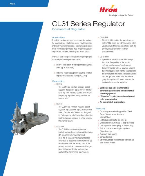
<strong>Gas</strong>CL31 Series Regula<strong>to</strong>rCommercial Regula<strong>to</strong>rApplicationsThe CL31 regula<strong>to</strong>r can produce substantial savingsfor users in lower initial costs, lower installation costsand lower maintenance costs. Optimum valve designlimits over boosting or rapid drop-off as <strong>the</strong> capacityrequirement changes, including fast on-off loads.The CL31 was designed for systems requiring highlyaccurate pressure regulation such as:> Utility “Fixed Fac<strong>to</strong>r” metering of relatively smallloads (up <strong>to</strong> 4000 scfh)> Industrial Heating equipment requiring constanthigh burner pressures (1 psig <strong>to</strong> 20 psig)Description> CL31N- The CL31N is a constant pressure loadedregula<strong>to</strong>r that utilizes a pilot with no internalrelief (N). This regula<strong>to</strong>r can be used wherepsig <strong>to</strong> psig regulation is required with nointernal relief.> <strong>CL31R</strong>- The <strong>CL31R</strong> is a constant pressure loadedregula<strong>to</strong>r equipped with a pilot internal reliefvalve. The pilot relief valve is not designedfor “full capacity” relief, but ra<strong>the</strong>r <strong>to</strong> limit <strong>the</strong>loading chamber pressure <strong>to</strong> a safe value in<strong>the</strong> event of failure.> CL-31IMN- The CL31IMN is a constant pressureloaded regula<strong>to</strong>r featuring Internal Moni<strong>to</strong>ring(IM) operation with no pilot internalrelief (N). It provides <strong>the</strong> important addedadvantage of a second, bubble-tight lock-upseat in series with <strong>the</strong> primary seat. If <strong>the</strong>primary seat fails <strong>to</strong> close or control <strong>the</strong> gasflow, <strong>the</strong> Internal Moni<strong>to</strong>r seat assumescontrol of <strong>the</strong> downstream gas pressure.> CL-31IMR- The CL31IMR provides <strong>the</strong> same featuresas <strong>the</strong> ‘IMN’ model but with <strong>to</strong>ken pilot reliefvalve backup of <strong>the</strong> moni<strong>to</strong>r orifice if both <strong>the</strong>primary seat and moni<strong>to</strong>r seat failsimultaneously.> CL-31IMRV- Operation is identical <strong>to</strong> <strong>the</strong> ‘IMR’ exceptthat at no flow position of <strong>the</strong> moni<strong>to</strong>rorifice a small volume of gas is ventedthrough <strong>the</strong> relief valve <strong>to</strong> serve as a signalthat <strong>the</strong> regula<strong>to</strong>r is on moni<strong>to</strong>r operation and<strong>the</strong> primary seat has failed. No gas is venteduntil <strong>the</strong> gas load is less than <strong>the</strong> volumegoing through <strong>the</strong> orifice vent hole and <strong>the</strong>regula<strong>to</strong>r is on moni<strong>to</strong>r operation.> Controlled size pilot brea<strong>the</strong>r orificeeliminates pulsation and provides normalbreathing operation> “S<strong>to</strong>p stem” in pilot insures <strong>to</strong>ken internalrelief valve operation> No special start-up proceduresFeatures> Constant pressure loading provides “FixedFac<strong>to</strong>r” Measurement AccuracyInternal Bleed> Light closing spring for low lock-up> Wide outlet pressure range (1 psig <strong>to</strong> 20 psig> One adjustable outlet spring (N version only)> Built in strainer screen in pilot regula<strong>to</strong>r(N version only)> Extremely light weight> Compact design> Safety advantage of second gas tight lock-upseat with IM Version
Shipping weightFour regula<strong>to</strong>rs per boxBox weight: 38 lbs.CL31 Dimensions (inches)ValveBodyA B C D E F G H J3/4 & 1 3-3/4 2-1/81-1/4 4 2-1/88 6-1/2 2 7-13/16 5-13/16 13 32 CL31 Series Commercial Regula<strong>to</strong>r
Operational SchematicShown with N-type pilotNote: valve shown in closed position.CL31 Series Commercial Regula<strong>to</strong>r 3
CL31 Series Commercial Regula<strong>to</strong>r – Models N and RCapacity Table (1% Absolute Droop*)Capacities in SCFH of 0.6 S.G. gas; base conditions of 14.7 PSIA and 60° F.Typical Capacity Info.Manufacturer <strong>Itron</strong> Inlet <strong>Pressure</strong>Type and model <strong>CL31R</strong>(PSIG)Outlet <strong>Pressure</strong>(PSIG)Orifice Size1/8" 3/16" 1/4" 3/8"Regula<strong>to</strong>r 2 1 300 300 500Inlet size: 1-1/4"1 400 500 9503Outlet size: 1-1/4" 2 325 350 1650Spring color: Varies1 325 550 850 16505Position 5 2 275 500 800 14501 400 825 1450 2550102 400 825 1450 25505 400 625 1050 17001 500 1025 1750 33002 500 1025 1750 3300155 500 1025 1700 275010 400 700 1000 17001 575 1275 2100 37002 575 1275 2100 3700205 575 1200 2100 350010 500 1075 1750 300015 400 825 800 17001 700 1600 2800 40002 700 1600 2800 4000305 700 1600 2800 400010 700 1600 2800 400015 700 1450 2100 400020 575 1200 1900 32001 900 1975 3400 40002 900 1975 3400 4000405 900 1975 3400 400010 900 1975 3400 400015 900 1975 3300 400020 900 1850 3300 40001 1075 2350 4000 40002 1075 2350 4000 4000505 1075 2350 4000 400010 1075 2350 4000 400015 1075 2350 4000 400020 1075 2350 4000 4000Notes:3/4-inch outlet pipe size limits <strong>the</strong> capacity <strong>to</strong> 2000 SCFH.1-inch outlet pipe size limits <strong>to</strong> 3000 SCFH.*Individual regula<strong>to</strong>r performance may vary from data shown.Inlet pressure is <strong>to</strong>o low <strong>to</strong> achieve desired outlet pressure.CL31 Series Commercial Regula<strong>to</strong>r 7
Notes:3/4-inch outlet pipe size limits <strong>the</strong> capacity <strong>to</strong> 2000 SCFH.1-inch outlet pipe size limits <strong>to</strong> 3000 SCFH.*Individual regula<strong>to</strong>r performance may vary from data shown.Do not operate orifice in shaded inlet pressure area.Orifice SizeOutletInlet <strong>Pressure</strong> (PSIG) <strong>Pressure</strong> 1/8" 3/16" 1/4" 3/8"(PSIG)1 1200 2675 4000 40002 1200 2675 4000 40005 1200 2675 4000 40006010 1200 2675 4000 400015 1200 2675 4000 400020 1200 2675 4000 40001 1400 3150 40002 1400 3150 40005 1400 3150 40007510 1400 3150 400015 1400 3150 400020 1400 3150 40001 1700 4000 40002 1700 4000 40001005 1700 4000 400010 1700 4000 400015 1700 4000 400020 1700 4000 40001 2100 4000 40002 2100 4000 40001255 2100 4000 400010 2100 4000 400015 2100 4000 400020 2100 4000 40008 CL31 Series Commercial Regula<strong>to</strong>r
CL31 Performance Curves5, 10 PSIG Set Point CL-31 Performance CurvesType and model <strong>CL31R</strong> 5 PSIG Set PointInlet sizeOutlet sizeOrifice size1-1/4” NPT1-1/4” NPT1/4-inchAll test results are reported at a base of14.7 PSIG at 60º F and with 0.6 S.G.gas.Outlet pressure - psigRate of flow - scfhCL-31 Performance Curves10 PSIG Set PointOutlet pressure - psigRate of flow - scfhCL31 Series Commercial Regula<strong>to</strong>r 9
A. Standard regula<strong>to</strong>r and upstream moni<strong>to</strong>r orifice. B. Standard regula<strong>to</strong>r orifice failed; upstream moni<strong>to</strong>r orificecontrol.C. Main orifice failed - upstream moni<strong>to</strong>r orifice lock-up.Inlet pressureOutlet pressureD. V option - vents a small volume of gas <strong>to</strong> atmospherethrough relief valve.Principle of OperationA. Normal operation. The internal moni<strong>to</strong>r IM orifice performs like a standard regula<strong>to</strong>r and moni<strong>to</strong>r regula<strong>to</strong>r in that main orifice andvalve seat actuate <strong>to</strong> control outlet flow and pressure under normal flow conditions. If <strong>the</strong>re is no demand, <strong>the</strong> main seat and internalmoni<strong>to</strong>r orifice will close.B. Moni<strong>to</strong>r operation. If <strong>the</strong> main valve seat fails <strong>to</strong> control <strong>the</strong> gas flow and pressure due <strong>to</strong> foreign matter between <strong>the</strong> seat andorifice face, or if <strong>the</strong> seat is eroded, <strong>the</strong> internal moni<strong>to</strong>r orifice au<strong>to</strong>matically goes in<strong>to</strong> operating position at a slightly higher outletpressure (see Internal Moni<strong>to</strong>r Lock-up <strong>Pressure</strong> table). Any time <strong>the</strong> pressure on <strong>the</strong> main diaphragm exceeds <strong>the</strong> force of <strong>the</strong> fixedmoni<strong>to</strong>r spring, <strong>the</strong> increased outlet pressure causes <strong>the</strong> main valve seat <strong>to</strong> push against <strong>the</strong> sliding orifice. The sliding orificecompresses <strong>the</strong> moni<strong>to</strong>r spring and positions <strong>the</strong> moni<strong>to</strong>r orifice <strong>to</strong> control <strong>the</strong> gas flow. The IM orifice now functions as a moni<strong>to</strong>rregula<strong>to</strong>r and continues <strong>to</strong> moni<strong>to</strong>r as long as <strong>the</strong> main seat fails <strong>to</strong> control at <strong>the</strong> normal adjusted outlet pressure. If <strong>the</strong> gas loaddemand is increased beyond <strong>the</strong> internal moni<strong>to</strong>r's capacity, <strong>the</strong> outlet pressure is reduced <strong>to</strong> normal adjusted pressure and <strong>the</strong>regula<strong>to</strong>r resumes normal regulation.C. Moni<strong>to</strong>r lock-up. If <strong>the</strong> demand for gas is decreased <strong>to</strong> zero flow during moni<strong>to</strong>r operation, <strong>the</strong> sliding orifice continues <strong>to</strong> closeuntil its orifice is in <strong>the</strong> gas tight position (moni<strong>to</strong>r lock-up) against <strong>the</strong> BUNA-N moni<strong>to</strong>r valve seat. (See <strong>the</strong> Internal Moni<strong>to</strong>r Lock-up<strong>Pressure</strong> table for <strong>the</strong> outlet pressure required for internal moni<strong>to</strong>r lock-up.)D. Vent hole V option. On installations where a small volume of over-pressure gas can be safely vented <strong>to</strong> <strong>the</strong> atmosphere, <strong>the</strong>advantages of both <strong>the</strong> pilot relief valve and moni<strong>to</strong>r safety can be combined. If <strong>the</strong> flow is decreased <strong>to</strong> zero or just greater thanzero, <strong>the</strong> vent hole in <strong>the</strong> internal moni<strong>to</strong>r orifice allows gas <strong>to</strong> slowly bleed downstream and cause <strong>the</strong> pressure <strong>to</strong> rise <strong>to</strong> <strong>the</strong> reliefpoint of <strong>the</strong> pilot's internal relief valve. The gas <strong>the</strong>n bleeds <strong>to</strong> <strong>the</strong> atmosphere indicating a problem with <strong>the</strong> regula<strong>to</strong>r.Internal Moni<strong>to</strong>r Lock-up <strong>Pressure</strong>Outlet pressure set point (PSIG) Pilot spring IM lock-up pressure (PSIG)1 Orange 1.52 Brown 2.55 Green 5.610 Black 10.815 Blue 16.220 Blue 21.2Note: The above tests were conducted using a 0.1-inch diameter nylon rod glued <strong>to</strong> <strong>the</strong> valve seat.10 CL31 Series Commercial Regula<strong>to</strong>r
CL31 Series Commercial Regula<strong>to</strong>r – Models IMR, IMRV, and IMNCapacity Table (1% Absolute Droop*)Typical Capacity Info.Capacities in SCFH of 0.6 S.G. gas; base conditions of 14.7 PSIA and 60° F.Orifice SizeManufacturer <strong>Itron</strong> Inlet <strong>Pressure</strong> Outlet <strong>Pressure</strong>Type and model CL31IM(PSIG)(PSIG)1/8" 3/16" 1/4" 5/16"Regula<strong>to</strong>r 2 1 300 300 300Inlet size: 1-1/4"1 400 475 500Outlet size: 1-1/4"32 300 325 350Spring color: Varies1 325 550 675 850Position 552 275 500 600 6801 400 825 1050 1250102 400 825 1025 12505 400 625 850 10001 500 1025 1400 16502 500 1025 1375 1650155 500 950 1275 152510 400 625 900 10501 575 1200 1700 20002 575 1200 1700 2000205 575 1200 1625 200010 500 1050 1200 172515 400 750 900 12501 700 1575 2275 27002 700 1575 2275 2700305 700 1575 2250 270010 700 1575 2050 255015 700 1450 1900 227520 575 1200 1625 19501 900 1900 2850 33002 900 1900 2850 33005 900 1900 2850 33004010 900 1900 2750 330015 900 1900 2575 310020 900 1775 2500 30001 1075 2250 3400 40002 1075 2250 3400 40005 1075 2250 3400 40005010 1075 2250 3300 400015 1075 2250 3250 400020 1075 2200 3175 4000Notes:3/4-inch outlet pipe size limits <strong>the</strong> capacity <strong>to</strong> 2000 SCFH.1-inch outlet pipe size limits <strong>the</strong> capacity <strong>to</strong> 3000 SCFH.*Individual regula<strong>to</strong>r performance may vary from data shown.Inlet pressure is <strong>to</strong>o low <strong>to</strong> achieve desired outlet pressure.CL31 Series Commercial Regula<strong>to</strong>r 11
Capacities in SCFH of 0.6 S.G. gas; base conditions of 14.7 PSIA and 60° FOrifice SizeInlet <strong>Pressure</strong>(PSIG)Outlet <strong>Pressure</strong>(PSIG)1/8" 3/16" 1/4" 5/16"Notes:60751001251 1200 2575 3900 40002 1200 2575 3900 40005 1200 2575 3900 400010 1200 2575 3900 400015 1200 2575 3900 400020 1200 2575 3900 40001 1400 3075 40002 1400 3075 40005 1400 3075 400010 1400 3075 400015 1400 3075 400020 1400 3075 40001 1700 3600 40002 1700 3600 40005 1700 3600 400010 1700 3600 400015 1700 3600 400020 1700 3600 40001 2100 4000 40002 2100 4000 40005 2100 4000 400010 2100 4000 400015 2100 4000 400020 2100 4000 40003/4-inch outlet pipe size limits <strong>the</strong> capacity <strong>to</strong> 2000 SCFH.1-inch outlet pipe size limits <strong>the</strong> capacity <strong>to</strong> 3000 SCFH.*Individual regula<strong>to</strong>r performance may vary from data shown.Do not operate orifice in shaded inlet pressure area.12 CL31 Series Commercial Regula<strong>to</strong>r
Assembly PositionsCL31 Series Commercial Regula<strong>to</strong>r 13
Parts ListCL31 RCL31 N14 CL31 Series Commercial Regula<strong>to</strong>r
Item No. Part No. Quantity Required per Regula<strong>to</strong>r ModelDescriptionNR1 753194 1 Upper diaphragm case, vent 1/4" pipe753199 1 1 Upper diaphragm case, vent 3/8" pipe2 1 1 Seal cap - please specify:760001 With seal wire hole760011 Without seal wire hole4 765503 1 1 Seal cap gasket18A 754721 1 1 S<strong>to</strong>p stem spacer - upper18B 754725 1 1 S<strong>to</strong>p stem spacer - lower21 752124 1 1 Lower diaphragm case - 4:1 lever ratio22 761231 1 1 Valve linkage lever - 4:1 lever ratio23 754021 1 1 Valve stem24 765021 1 1 Valve seat - Buna N - standard27 751913 1 1 Valve body retainer plate - aluminum28 755725 1 1 Retainer plate snap ring29 755141 2 2 Valve linkage pin screw30 754831 1 1 Valve linkage pin36 766121 1 1 Diaphragm37A 761031 1 1 Upper diaphragm plate37B 761025 1 1 Upper diaphragm plate - steel38A 761025 1 1 Lower diaphragm plate - steel38B 756091 1 1 Lower diaphragm plate39 754331 1 1 S<strong>to</strong>p stem44 754901 1 1 S<strong>to</strong>p stem guide bushing47 761495 1 1 Closing spring guide56 762119 1 1 Closing spring - light green57 1 1 Valve bodies - straight - specify size750060 3/4" x 3/4" NPT with 1/8" NPT750069 3/4" x 1" NPT with 1/8" NPT750078 1" x 1" NPT with 1/8" NPT750110 3/4" x 1-1/4" NPT with 1/8" NPT750119 1" x 1-1/4" NPT with 1/8" NPT750134 1-1/4" x 1-1/4" NPT with 1/8" NPT58 1 1 Orifice, Brass - specify size757255 1/8" Diameter757259 3/16" Diameter757263 1/4" Diameter757271 3/8" Diameter59 761753 1 1 Loading ring61 765753 1 1 Valve body gasket62 755386 2 2 Retainer plate screw - hex head - 5/16" - 18 x 1-1/4" Lg.63 769205 1 1 Curved regula<strong>to</strong>r plate64 755304 8 8 Case screw - hex head - 1/4" - 20 x 3/4"65 755661 8 8 Case nut - hex head - 1/4" – 20CL31 Series Commercial Regula<strong>to</strong>r 15
Item No.Part No.Quantity Required per Regula<strong>to</strong>r ModelNRDescription67A 768133 1 Nipple - 3/8" NPT x 2"768123 1 Nipple - 1/4" NPT x 2"67B 768101 1 1 Pipe nipple, male - 1/8" x 1/4" NPT steel69A 768507 1 1 Control line, 1/4" steel69B 768541 1 1 Control line, 1/4" D tube – steel70A 768251 1 1 90° Male elbow - 1/4" tube x 1/8" NPTF - steel70B 768257 1 1 90° Male Elbow - 1/4" Tube x 1/4" NPTF - steel*optional control line with filter assembly –Call <strong>Itron</strong>, Owen<strong>to</strong>n, KY71 700321 1 Pilot assembly - N version only - blue spring762631 1 Orange - adjustment spring only762633 1 Brown - adjustment spring only762635 1 Green - adjustment spring only762637 1 Black - adjustment spring only762639 1 Blue - adjustment spring only72 755621 1 1 S<strong>to</strong>p stem nut (hex) #10-2473 769401 1 1 Warning sticker - seal cap83 766273 1 1 90° Female elbow - 1/4" tube x 1/4" NPT - steel84 768291 1 1 90° Street elbow - 1/4" NPT - steel85 755731 1 1 Stem guide bushing retainer ring90 768481 1 1 Control line filter16 CL31 Series Commercial Regula<strong>to</strong>r
Vent Lines for Regula<strong>to</strong>rsWhen constructing vent lines <strong>to</strong> be attached <strong>to</strong> regula<strong>to</strong>rs installed indoors, follow a few basic rules:a. Never use pipe sizes smaller than <strong>the</strong> vent size; smaller pipe sizes restrict <strong>the</strong> gas flow. If a long gas run must be used, <strong>Itron</strong>advises increasing <strong>the</strong> pipe one nominal size every ten feet <strong>to</strong> keep <strong>the</strong> flow restriction as low as possible.b. Keep <strong>the</strong> vent line length as short as possible <strong>to</strong> minimize <strong>the</strong> restriction and reduce <strong>the</strong> vent's tendency <strong>to</strong> cause regula<strong>to</strong>rpulsation.c. Support <strong>the</strong> vent pipe <strong>to</strong> eliminate strain on <strong>the</strong> regula<strong>to</strong>r diaphragm case.d. Always point outdoor vent pipes in <strong>the</strong> downward position <strong>to</strong> reduce <strong>the</strong> possibility of rain, snow, sleet, and o<strong>the</strong>r moistureentering <strong>the</strong> pipe. Install a bug screen in <strong>the</strong> end of <strong>the</strong> pipe.e. Do not locate <strong>the</strong> vent line terminus near windows, fans, or o<strong>the</strong>r ventilation equipment. See <strong>the</strong> installation instructions furnishedwith <strong>the</strong> regula<strong>to</strong>r.f. Adhere <strong>to</strong> all applicable codes and regulations.g. If your vent pipe causes regula<strong>to</strong>r pulsation, consult your sales representative or manufacturer.h. <strong>Itron</strong> strongly recommends running a separate vent line for each regula<strong>to</strong>r. Headers with various installed devices can causeregula<strong>to</strong>r malfunction.Caution Ensure <strong>the</strong> end of <strong>the</strong> vent line is away from ANY potential ignition sources. It is <strong>the</strong> installer’s responsibility <strong>to</strong> ensure <strong>the</strong>vent line is exhausting <strong>to</strong> a safe environment.InstallationWarning <strong>Itron</strong> does not endorse or warrant <strong>the</strong> completeness or accuracy of any third party regula<strong>to</strong>r installation procedures orpractices, unless o<strong>the</strong>rwise provided in writing by <strong>Itron</strong>. Follow your company's standard operating procedures regarding <strong>the</strong> use ofpersonal protection equipment (PPE). Adhere <strong>to</strong> guidelines issued by your company in addition <strong>to</strong> those given in this document wheninstalling regula<strong>to</strong>rs.a. Remove all shipping plugs from <strong>the</strong> regula<strong>to</strong>r inlet, outlet, and vent before installation.b. Verify <strong>the</strong> piping interior and regula<strong>to</strong>r inlet and outlet are clean and free of dirt, pipe dope, and o<strong>the</strong>r debris. Dirt and o<strong>the</strong>rforeign materials entering <strong>the</strong> regula<strong>to</strong>r can cause a loss of pressure control.c. Apply pipe joint sealant <strong>to</strong> <strong>the</strong> male pipe threads. Do not use pipe joint material on <strong>the</strong> regula<strong>to</strong>r's female threads. Joint sealantcould become lodged in <strong>the</strong> regula<strong>to</strong>r and cause a loss of pressure control.d. <strong>Gas</strong> must flow through <strong>the</strong> regula<strong>to</strong>r's valve body in <strong>the</strong> direction cast on <strong>the</strong> regula<strong>to</strong>r body. <strong>Gas</strong> flowing in <strong>the</strong> wrong directioncan overpressure and cause damage <strong>to</strong> <strong>the</strong> regula<strong>to</strong>r.e. The pilot diaphragm casing can be mounted in any position relative <strong>to</strong> <strong>the</strong> body through a full 360° angle at 90° increments.f. When <strong>the</strong> regula<strong>to</strong>r is installed OUTDOORS, <strong>the</strong> vent must always be positioned so that rain, snow, moisture or foreign particlescannot enter <strong>the</strong> vent opening. <strong>Itron</strong> recommends positioning <strong>the</strong> pilot vent downward <strong>to</strong> avoid entry of water or o<strong>the</strong>r matterwhich could interfere with <strong>the</strong> proper operation of <strong>the</strong> regula<strong>to</strong>r. The vent should be located away from building eaves, windowopenings, building air intakes and above <strong>the</strong> expected snow level at <strong>the</strong> site. The vent opening should be inspected periodically<strong>to</strong> insure it does not become blocked by foreign material as outlined in DOT PHMSA-RSPA-2004-19856.g. When <strong>the</strong> regula<strong>to</strong>r is installed INDOORS, <strong>the</strong> vent must be piped <strong>to</strong> <strong>the</strong> outside atmosphere using <strong>the</strong> shortest length of pipe,<strong>the</strong> fewest possible pipe elbows, and a pipe diameter as large as <strong>the</strong> vent size or larger. USING VENT PIPE SMALLER THANTHE VENT CONNECTION LIMITS THE REGULATOR’S INTERNAL RELIEF VALVE CAPACITY. The outlet end of <strong>the</strong> pipemust be protected from moisture and <strong>the</strong> entrance of foreign particles. The regula<strong>to</strong>r should be specified by <strong>the</strong> user with <strong>the</strong> sizevent and pipe threads desired <strong>to</strong> make <strong>the</strong> vent pipe connection.CL31 Series Commercial Regula<strong>to</strong>r 17
Start -up Procedurea. Mount a pressure gauge downstream of <strong>the</strong> regula<strong>to</strong>r <strong>to</strong> moni<strong>to</strong>r <strong>the</strong> downstream pressure.b. With <strong>the</strong> downstream pressure valve closed, slowly open <strong>the</strong> inlet valve. The outlet pressure should rise <strong>to</strong> slightly more than <strong>the</strong>set-point. Verify <strong>the</strong>re are no leaks and all connections are tight.c. The regula<strong>to</strong>r was pre-set at <strong>the</strong> fac<strong>to</strong>ry <strong>to</strong> match order specifications. If necessary, adjust <strong>the</strong> outlet pressure by removing <strong>the</strong>seal cap on <strong>the</strong> <strong>to</strong>p of <strong>the</strong> pilot spring housing and adjusting <strong>the</strong> ferrule or screw inside <strong>the</strong> pilot spring housing using a large fla<strong>the</strong>adscrewdriver. With a small amount of gas flowing through <strong>the</strong> regula<strong>to</strong>r, rotate <strong>the</strong> pilot ferrule clockwise <strong>to</strong> raise <strong>the</strong> outletpressure or counter-clockwise <strong>to</strong> lower <strong>the</strong> outlet pressure.d. Replace <strong>the</strong> seal cap and check for leaks after <strong>the</strong> desired outlet pressure is achieved.The regula<strong>to</strong>r is ready for operation.Safety WarningThis product, as of <strong>the</strong> date of manufacture, is designed and tested <strong>to</strong> conform <strong>to</strong> all governmental and industry safety standardsas <strong>the</strong>y may apply <strong>to</strong> <strong>the</strong> manufacturer. The purchaser/user of this product must comply with all fire control, building codes, ando<strong>the</strong>r safety regulations governing <strong>the</strong> application, installation, operation, and general use of this regula<strong>to</strong>r <strong>to</strong> avoid leaking gashazards resulting from improper installation, startup or use of this product.<strong>Itron</strong> strongly recommends installation by a qualified professional and periodic inspection of pressure regula<strong>to</strong>rs (inspections maybe required by local applicable codes or regulations).Inspections should include checking for gas quality, cycle numbers, external environmental changes, and operating conditionsthat impact wear on <strong>the</strong> regula<strong>to</strong>r's moving parts. To ensure safe and efficient operation of this product, replace worn ordamaged parts found during inspection.18 CL31 Series Commercial Regula<strong>to</strong>r
BURNERPARTS.COM2011 WILLIAMSBURG ROADRICHMOND, VIRGINIA 23231(T) 804-236-3881(F) 804-236-3882sales@burnerparts.com