B UTTERFLY V ALVES - valves.com.ua
B UTTERFLY V ALVES - valves.com.ua
B UTTERFLY V ALVES - valves.com.ua
- No tags were found...

You also want an ePaper? Increase the reach of your titles
YUMPU automatically turns print PDFs into web optimized ePapers that Google loves.
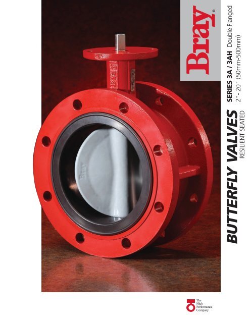
utterfly <strong>valves</strong>resilient seated®series 3A / 3AH Double Flanged2"- 20" (50mm-500mm)TheHighPerformanceCompany
FEATURESBray Controls is proud to offer a high q<strong>ua</strong>lity line offlanged butterfly <strong>valves</strong> to meet the requirements oftoday’s market. Combining years of field applicationexperience, research and development, Bray hasdesigned many unique features in the Series 3A/3AHnot previously available. The results are longer servicelife, greater reliability, ease of parts replacement andinterchangeability of <strong>com</strong>ponents.Bray’s Series 3A/3AH <strong>valves</strong> are a double flangeddesign which can be used for dead-end service. AllBray <strong>valves</strong> are tested to 110% of full pressure ratingbefore shipment.A major design advantage of Bray valve product lines isinternational <strong>com</strong>patibility. The same valve is <strong>com</strong>patiblewith most world flange standards – ASME Class 125/150,BS 10 Tables D and E, BS 4504 NP 10/16, DIN ND 10/16,AS 2129 and JIS10. In addition, the <strong>valves</strong> are designed to <strong>com</strong>plywith ISO 5752 - Table 2 (short pattern) face-to-face and ISO 5211act<strong>ua</strong>tor mounting flanges. Therefore, one valve design can beused in many different world markets.Bray interchangeability and <strong>com</strong>patibility offers the bestin uniformity of product line and low-cost performancein the industry today.DISCSpherically machined and hand polished to provide a bubbletightshut off, minimum torque, and longer seat life. Standardmaterial is Nylon 11 coated ductile Iron. Other materialsavailable on request.Stem RetainingAssemblyAct<strong>ua</strong>torMountingFlange/StemConnectionExtendedNeckPRIMARY AND SECONDARY SEALSThe primary seal is achieved by pre-loaded contactof spherically machined hand polished disc hubswith unique molded seat flat surfaces. This sealingmethod isolates the flowing media from the stemand body material at all angles of valve disc seating.A secondary seal is achieved by an interferencefit of the stem and seat hole diameters.STEM RETAINING ASSEMBLYThe stem is retained in the body by means of a uniqueStainless Steel “Spirolox ® ” retaining ring, a thrust washerand two C-rings, manufactured from brass as standard,stainless steel upon request. The retaining ring may be easilyremoved with a standard hand tool. The stem retaining assemblyprevents unintentional removal of the stem during field service.DiscFlangedBodyDisc & StemConnectionSeatStem Retaining AssemblyStem BushingStem SealNylon 11 CoatingA thermoplastic coating produced from a vegetable base andis USDA Approved, as well as, certified to ASME/NSF61for water service. It is inert to fungus growth and mold,has excellent resistance to impact and provides a very lowcoefficient of friction.STEM BUSHING Non-corrosive, heavy duty acetal bushingabsorbs act<strong>ua</strong>tor side thrusts.STEM SEAL Double “U” cup seal design is self-adjusting,gives positive sealing in both directions, and prevents externalsubstances from entering the stem bore.EXTENDED NECK Extended neck length allows for 2" of pipinginsulation and is easily accessible for mounting act<strong>ua</strong>tors.Nylon 11 also has superior corrosion resistance and has beenused successfully in many applications such as water, cement,food and seawater. Bray's Nylon 11 coating has been salt spraytested in excess of 2000 hours and used in seawater immersionservice for over 25 years without any deterioration of the coatingresulting in no corrosion to the coated metal <strong>com</strong>ponents. Asa result, the use of Nylon 11 in seawater with elevated chloridelevels between 30,000 - 40,000 ppm continues to increase.“Spirolox ® ” designation is a registered trademark of Kaydon Ring and Seal, Inc.2
selection dataFLANGE REQUIREMENTSBray <strong>valves</strong> are designed for installation between ASME Class125/150 lb. weld-neck or slip-on flanges, BS 10 Tables D &E, BS 4504 NP 10/16, DIN ND 10/16, AS 2129 and JIS 10,either flat faced or raised faced. While weld-neck flanges arere<strong>com</strong>mended, Bray has specifically designed its valvePRESSURE RATINGSFor Bi-directional Bubble-Tight Shut-Off and Dead-End ApplicationsSERIES 3ASize Range Standard Disc Reduced Disc*2"-12" (50-300 mm) 175 psig (12.1 bar) 50 psig (3.5 bar)14"-20" (350-500 mm) 150 psig (10.3 bar) 50 psig (3.5 bar)SERIES 3AH2"-20" (50-500 mm) 250 psig (17.2 bar) NA NA*For low pressure application, Bray offers a standard reduced disc diameter to decrease seating torques and to extendseat life, thus increasing the valve’s performance and reducing act<strong>ua</strong>tor costs for the customer consult factory.VELOCITY LIMITS FOR ON-OFF SERVICEFluids – 30 ft/sec (9 m/s)Gases – 175 ft/sec (54 m/s)seat to work with slip-on flanges, thus eliminating <strong>com</strong>monfailures of other butterfly valve designs. When using raisedface flanges be sure to properly align valve and flange. TypeC stub-end flanges are not re<strong>com</strong>mended.øFøGBolt CircleFlangeDIMENSIONS SERIES 3A/3AH - ins (mm)Valve Sizeins(mm)A B C D* E FTop Plate DrillingBoltCircleNo.HolesHoleDia.G H J K LFlange Bolting DataBoltCircleNo.HolesThreadsUNC-2B45°2(50)6.50(165)4.25(108)2.00(51)2.84(72)5.50(140)3.54(90)2.76(70)4.39(9.9).55(14).39(10)1.25(32)X.79(20)4.75(121)4 5/8-112.5(65)7.28(185)4.41(112)2.50(64)3.34(85)6.00(152)3.54(90)2.76(70)4.39(9.9).55(14).39(10)1.25(32)X.79(20)5.50(140)4 5/8-113(80)7.87(200)4.49(114)3.00(76)4.03(102)6.25(159)3.54(90)2.76(70)4.39(9.9).55(14).39(10)1.25(32)X.87(22)6.00(152)4 5/8-114(100)8.66(220)5.00(127)4.00(102)5.16(131)7.00(178)3.54(90)2.76(70)4.39(9.9).63(16).43(11)1.25(32)X.95(24)7.50(191)8 5/8-115(125)9.84(250)5.51(140)5.00(127)6.16(156)7.50(190)3.54(90)2.76(70)4.39(9.9).75(19).51(13)1.25(32)X1.03(26)8.50(216)8 3/4-106(150)8(200)11.22(285)13.50(343)5.51(140)5.98(152)5.75(146)7.75(197)7.02(178)9.47(241)8.00(203)9.50(241)3.54(90)5.91(150)2.76(70)4.92(125)44.39(9.9).57(14.5).75(19).87(22).51(13).63(16)1.25(32)1.25(32)1.78(45)5.00(127)1.03(26)1.18(30)9.50(241)11.75(298)8 3/4-108 3/4-10(Across Flats)HJ10(250)15.94(405)6.50(165)9.75(248)11.47(291)10.75(273)5.91(150)4.92(125)4.57(14.5)1.18(30).87(22)2.00(51)7.35(187)1.26(32)14.25(362)12 7/8-912(300)19.00(483)7.01(178) 11.75(298)13.47(342)12.25(311)5.91(150)4.92(125)4.57(14.5)1.18(30).87(22)2.00(51)9.53(242)1.26(32)17.00(432)12 7/8-9EValve SizeA B C D* E FTop Plate Drillingins(mm)14(350)21.00(533)7.48(190) 13.25(337)15.28(388)13.62(346)5.91(150)BoltCircle4.92(125)No.Holes4HoleDia..57(14)G1.38(35)KeySize J K L.39x.39(10x10)2.00(51)11.07(281)1.42(36)Flange Bolting DataBoltCircle18.75(476)No.HolesThreadsUNC-2B12 1-8KCD16(400)23.50(597)8.51(216) 15.25(387)17.41(442)14.75(375)5.91(150)4.92(125)4.57(14)1.38(35).39x.39(10x10)2.00(51)12.81(325)1.50(38)21.25(540)16 1-818(450)25.20(640)8.74(222) 17.25(438)19.47(495)16.00(406)8.27(210)6.50(165)4.81(21)1.97(50).47x.39(12x10)2.50(64)15.02(381)1.65(42)22.75(578)16 11/8-720(500)28.15(715)9.02(229) 19.25(489)21.59(548)17.25(438)8.27(210)6.50(165)4.81(21)1.97(50).47x.39(12x10)Note: K dim is disc chordal dimension at valve face* Flat Faced Flange Available - Contact factory for dimensional information2.50(64)17.15(436)1.65(42)25.00(635)20 11/8-7BL3
RECOMMENDED SPECIFICATIONS FOR BRAY SERIES 3A/3AH SHALL BE:• Polyester coated, cast iron, double flanged bodies.• Spherically machined, hand polished disc edge and• Complies with ISO 5752 - Table 2 (short pattern) face-to-face hub for minimum torque and maximum sealing• With flange locating holes that meet ASME Class 125/150capability.(or BS 10 Tables D & E, BS 4504 NP 10/16, DIN ND 10/16, • Equipped with non-corrosive bushing and self-AS 2129 and JIS 10) drillings.adjusting stem seal.• Through-stem direct drive double “D” design requiring no • Bi-directional and tested to 110% of full rating.disc screws or pins to connect stem to disc with no possible • Bi-directional dead-end pressure rating:leak paths in disc/stem connection.• Stem mechanically retained in body neck and no part of stemSeries 3A 2"-12" (50-300 mm) - 175 psi (12.2 bar)14"-20" (350-500 mm) - 150 psi (10.3 bar)or body exposed to line media.• Seat design with primary hub seal and a molded O-ring suitablefor weld-neck and slip-on flanges. Seat totally encapsulatesthe body with no flange gaskets required.Series 3AH 2"-20" (50-500 mm) - 250 psi (17.2 bar)• No field adjustment necessary to maintain optimumfield performance.• The valve shall be Bray Series 3A Double Flanged.• Valves available with CE marking.MATERIALS SELECTION 2"–20" (50mm-500mm)BODY:• Cast Iron ASTM A126 Class B• Ductile Iron ASTM A536• Cast Steel ASTM A216 WCBSEAT:• Aerospace - Bonded EPDM• Aerospace - Bonded BUNA-N (NBR)• Aerospace - Bonded FKM*STEM:• 416 Stainless Steel ASTM A582 Type 416• 304 Stainless Steel ASTM A276 Type 304• 316 Stainless Steel ASTM A276 Type 316• MonelDISC:• Aluminum Bronze ASTM B148-954• Nylon 11 Coated Ductile IronASTM A536 Gr. 65-45-12• 316 Stainless Steel ASTM A351 CF8M• 304 Stainless Steel ASTM A351 CF8Additional materials are available. Please consult your Bray representative.*FKM is the ASTM D1418 designation for Fluorinated Hydrocarbon Elastomers (also called Fluoroelastomers).987654TEMPERATURE RANGE OF SEATSType Maximum MinimumEPDM +250°F (121°C) -40°F (-40°C)Buna-N +212°F (100°C) 0°F (-18°C)FKM* +400°F (204°C) 0°F (-18°C)WEIGHTS COMPONENTSValve Sizeins (mm) lbs (Kg) No. Qty. Description2 (50) 22 (10) 1 1 Body2.5 (65) 24 (11) 2 1 Seat3 (80) 28 (13) 3 1 Disc4 (100) 35 (16) 4 1 Stem5 (125) 45 (21) 5 1 Stem Seal6 (150) 59 (27) 6 1 Stem Bushing8 (200) 70 (32) 7 2 Stem Retainer10 (250) 132 (60) 8 1 Thrust Washer12 (300) 178 (81) 9 1 Retaining Ring14 (350) 258 (117)16 (400) 318 (144)18 (450) 459 (208)20 (500) 534 (242)3214
BODYOne-piece double flanged body. All bodiescan be drilled to be <strong>com</strong>patible with ASME125/150, PN10 or other international flangestandards. The Series 3A/3AH maybe bolted to allow downstream flangeremoval or cross-bolted for maximumresistance to line stresses.DISC AND STEM CONNECTIONFeatures a high-strength through stemdesign. The close tolerance, double “D”connection that drives the valve disc is anexclusive feature of the Bray valve. Thisinternal connection eliminates the needfor exposed disc-stem fasteners such asdisc screws and taper pins which areexposed to the line media and potentialcorrosion leading to the creation of leakpaths and disc-stem connection failures.Disc screws or taper pins, due to wearand corrosion, often require difficultmachining for disassembly. Disassemblyof the Bray stem is simply a matter ofpulling the stem out of the disc. Withoutfasteners obstructing the line flow, theCv values are higher than many other<strong>valves</strong>, turbulence is reduced, andpressure recovery is increased.ACTUATOR MOUNTINGFLANGE AND STEMCONNECTIONUniversally designed to ISO 5211for direct mounting of Bray poweract<strong>ua</strong>tors and man<strong>ua</strong>l operators. Thestem ends and top mounting flange arestandardized for interchangeabilitywith Bray act<strong>ua</strong>tors. Stem to act<strong>ua</strong>torconnections are double “D” for sizes2"-12" and keyed for sizes 14" - 20".BRAY SEAT DESIGNBrays seat design, aerospace-bonded tothe body, is designed to seal with slip-onor weld-neck flanges. Seat totally encasesthe valve interior to isolate the line mediafrom the body.Cv VALUES–VALVE SIZING COEFFICIENTValve Size5POLYESTER BODY COATINGBray’s standard product offers valvebodies with a polyester coating. Thiscoating provides excellent corrosion,abrasion and impact resistance.NOTE: Nylon 11 coating is availableas an option for valve bodies whereenvironmental protection is required.Disc Position-Degreesins (mm) 90° 80° 70° 60° 50° 40° 30° 20° 10°2 (50) 144 114 84 61 43 27 16 7 12.5 (65) 282 223 163 107 67 43 24 11 1.53 (80) 461 364 267 154 96 61 35 15 24 (100) 841 701 496 274 171 109 62 27 35 (125) 1376 1146 775 428 268 170 98 43 56 (150) 1850 1542 1025 567 354 225 129 56 68 (200) 3316 2842 1862 1081 680 421 241 102 1210 (250) 5430 4525 2948 1710 1076 667 382 162 1912 (300) 8077 6731 4393 2563 1594 1005 555 235 2714 (350) 10538 8874 5939 3384 2149 1320 756 299 3416 (400) 13966 11761 7867 4483 2847 1749 1001 397 4518 (450) 17214 14496 10065 5736 3643 2237 1281 507 5820 (500) 22339 18812 12535 7144 4536 2786 1595 632 72Cv is defined as the volume of water in USGPM that will flow through a given restriction or valveopening with a pressure drop of one (1) psi at room temperature.S3A EXPECTED SEATING/UNSEATING TORQUES - Lb-Ins (Nm)*Reduced DiscValve Size Full-Rated Pressure Valves - psi (bar)Diameterins (mm) 50 (3) 100 (7) 150 (10) 175 (12) 50 (3)2 (50) 125 (14) 130 (15) 135 (15) 140 (16) 125 (14)2.5 (65) 195 (22) 205 (23) 215 (24) 220 (25) 195 (22)3 (80) 260 (29) 275 (31) 290 (33) 297 (34) 260 (29)4 (100) 400 (45) 425 (48) 450 (51) 462 (52) 267 (30)5 (125) 615 (69) 670 (76) 725 (82) 755 (85) 410 (46)6 (150) 783 (88) 871 (98) 953 (108) 1003 (113) 537 (61)8 (200) 1475 (167) 1650 (186) 1825 (206) 1915 (216) 983 (111)10 (250) 2240 (253) 2520 (285) 2800 (316) 2940 (332) 1493 (169)12 (300) 3420 (386) 3870 (437) 4320 (488) 4545 (514) 2280 (258)14 (350) 4950 (559) 5700 (644) 6450 (729) - 3300 (373)16 (400) 6400 (723) 7700 (870) 9000 (1017) - 4267 (482)18 (450) 7850 (887) 9850 (1113) 11850 (1339) - 5267 (595)20 (500) 10300 (1164) 12900 (1458) 15500 (1752) - 6867 (776)*Consult factory for Series 3AH Seating/Unseating torques
Bray International - Houston, TexasBray ChinaFlow-Tek USABray CanadaBray United KingdomFlow-Tek ChinaBray MexicoBray BrazilBray BeneluxBray Pacific(Australia)Bray ChileRitepro CanadaBray GermanyBray PolandAll statements, technical information, andre<strong>com</strong>mendations in this bulletin are for generaluse only. Consult Bray representatives or factoryfor the specific requirements and material selectionfor your intended application. The right to changeor modify product design or product without priornotice is reserved.Patents issued and applied for worldwide.Bray ® is a registered trademark of Bray International, Inc.CONTrOLSA Division of BrAy INTErNATIONAL, Inc.13333 Westland East Blvd. Houston, Texas 77041281.894.5454 FAX 281.894.9499 www.bray.<strong>com</strong>© 2010 Bray International. All rights reserved.B-1047_EL_S3A-3AH_2010-01