VITOCELL 300 B Installation instructions - Viessmann
VITOCELL 300 B Installation instructions - Viessmann
VITOCELL 300 B Installation instructions - Viessmann

Create successful ePaper yourself
Turn your PDF publications into a flip-book with our unique Google optimized e-Paper software.
<strong>Installation</strong> <strong>instructions</strong><br />
for contractors<br />
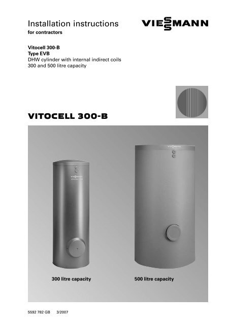
Vitocell�<strong>300</strong>�B<br />
Type�EVB<br />
DHW cylinder with internal indirect coils<br />
<strong>300</strong> and 500 litre capacity<br />
<strong>VITOCELL</strong> <strong>300</strong>�B<br />
5592�782�GB���3/2007<br />
<strong>300</strong>�litre capacity 500�litre capacity
2<br />
Safety <strong>instructions</strong><br />
Please follow these safety <strong>instructions</strong> closely to prevent accidents and<br />
material losses. For safety <strong>instructions</strong> in conjunction with boilers, see<br />
separate installation <strong>instructions</strong>.<br />
Safety regulations<br />
<strong>Installation</strong>, commissioning,<br />
inspection, maintenance and<br />
repairs must only be carried out<br />
by a competent person (heating<br />
engineer/ installation contractor).<br />
Observe all current safety<br />
regulations as defined by DIN,<br />
EN, DVGW, TRGI, TRF and VDE or<br />
locally applicable standards.<br />
See also the "Safety <strong>instructions</strong>" in<br />
the "Vitotec technical documentation"<br />
folder.<br />
Product information<br />
Before working on the equipment/<br />
heating system, isolate the power<br />
supply (e.g. by removing a separate<br />
mains fuse or by means of a main<br />
isolator) and safeguard against<br />
unauthorised reconnection.<br />
¨�Safety <strong>instructions</strong><br />
In this instruction manual, this<br />
heading denotes information which<br />
must be observed to prevent<br />
accidents and material losses.<br />
¨ This symbol denotes important<br />
information which must be<br />
observed to prevent material<br />
losses.<br />
DHW cylinder with internal indirect coils, made from stainless steel for<br />
heating domestic hot water in conjunction with boilers, district heating or<br />
low temperature heating systems for dual−mode operation.<br />
<strong>300</strong> and 500�litre capacity<br />
Suitable for systems conforming to DIN�1988, DIN�4751 and DIN�4753.<br />
DIN registration applied for.<br />
5592�782�GB
5592�782�GB<br />
DHW cylinder installation<br />
General information<br />
¨�Safety <strong>instructions</strong><br />
Install the DHW cylinder in a<br />
frost−protected and draught−free<br />
room. Otherwise it must be drained<br />
when not in use and there is a risk<br />
of frost.<br />
Provide adequate clearance from<br />
the wall so that the thermostat can<br />
be operated (if installed).<br />
WW<br />
STS<br />
HV1<br />
Z<br />
HR1<br />
STS/TH<br />
HV2<br />
HR2/STS<br />
KW<br />
A<br />
! Please note<br />
The thermal insulation must<br />
not be able to come into<br />
contact with naked flames.<br />
Exercise caution when welding<br />
and soldering.<br />
A only for <strong>300</strong>�litres capacity:<br />
Equipotential bonding<br />
(outer jacket)<br />
HR1 Heating water return *1<br />
HR2/STS Heating water return<br />
and cylinder temperature<br />
sensor for solar operation *2,�3<br />
HV1 Heating water flow *1<br />
HV2 Heating water flow *2<br />
KW Cold water<br />
STS Cylinder temperature sensor<br />
or control thermostat<br />
(upper internal indirect coil)<br />
STS/TH Cylinder temperature sensor<br />
or control thermostat and<br />
thermometer sensor<br />
(lower internal indirect coil) *3<br />
WW DHW<br />
Z DHW circulation<br />
*1The upper internal indirect coil is provided for connection to a boiler or a heat pump.<br />
*2The lower internal indirect coil is provided for connection to solar collectors or heat<br />
pumps.<br />
*3Recommended arrangement of the cylinder temperature sensor for solar operation:<br />
With threaded elbow (accessory) in the heating water return.<br />
3
4<br />
DHW cylinder installation (cont.)<br />
Installing a DHW cylinder with <strong>300</strong>�litres capacity<br />
1. Level the DHW cylinder with its<br />
adjustable feet.<br />
¨�Safety instruction<br />
Never extend the adjustable feet<br />
beyond a total length of 35�mm.<br />
2. Remove the top panel and the<br />
thermal insulation mat.<br />
3. Affix the cable channel.<br />
4. Route the sensor lead of the lower<br />
thermometer through the opening<br />
and the cable channel.<br />
7.<br />
6.<br />
2.<br />
5.<br />
5.<br />
3.<br />
4.<br />
5. Seal in the reducing connections<br />
and sensor wells.<br />
6. Secure the thermometer sensor<br />
on the outside of the contact<br />
spring of the sensor retainer (not<br />
in the groove) so that it is flush<br />
with the front of the spring.<br />
Note<br />
Never wrap insulating tape around<br />
the sensor.<br />
7. Insert the sensor retainer together<br />
with the sensor into the lower<br />
sensor well until it bottoms out.<br />
1.<br />
5592�782�GB
5592�782�GB<br />
DHW cylinder installation (cont.)<br />
Installing a DHW cylinder with 500�litres capacity<br />
! Please note<br />
The thermal insulation must not be able to come into contact with<br />
naked flames. Exercise caution when welding and soldering.<br />
All components required for fitting the thermal insulation can be found in the<br />
thermal insulation carton.<br />
3.<br />
1.<br />
1. Remove the pack containing the<br />
type plate from the cylinder body,<br />
and keep safe.<br />
2. Push the thermal insulation mat<br />
underneath the DHW cylinder.<br />
2.<br />
3. Level the DHW cylinder with its<br />
adjustable feet.<br />
¨�Safety instruction<br />
Never extend the adjustable feet<br />
beyond a total length of 35�mm.<br />
5
6<br />
DHW cylinder installation (cont.)<br />
2.<br />
5.<br />
1.<br />
7.<br />
1 Push the thermal insulation jacket<br />
onto the flange.<br />
2. Route the sensor lead of the upper<br />
thermometer (shorter lead) and<br />
the lower thermometer (longer<br />
lead) through the opening and<br />
push in the thermometers.<br />
3. Guide the sensor of the lower<br />
thermometer over the cylinder<br />
body to the back of the cylinder<br />
and out through the cut−out in the<br />
thermal insulation for the heating<br />
water flow (HV2 see page�3).<br />
6.<br />
Note<br />
Install the sensor into the sensor<br />
well as shown on page�8.<br />
3.<br />
4. Close the hooks on the closure<br />
strips.<br />
5. Insert the sensor of the upper<br />
thermometer into the hole of the<br />
cylinder cap until it bottoms out,<br />
then secure with a clip to prevent<br />
pulling out.<br />
6 Position the thermal insulation<br />
mat and lid.<br />
7. Push the logo (from the type plate<br />
pack) into the lid.<br />
4.<br />
5592�782�GB
5592�782�GB<br />
DHW cylinder installation (cont.)<br />
2.<br />
2.<br />
1.<br />
1.<br />
1. Seal in the reducing connections.<br />
2. Seal in the sensor well.<br />
3. Affix the type plate.<br />
3.<br />
7
8<br />
Installing the sensor well and the cylinder temperature sensor<br />
� The cylinder temperature sensor for the heating side is supplied in the<br />
package of the appropriate control unit. The solar side cylinder temperature<br />
sensor is supplied in the package of the solar control unit.<br />
� Secure the sensor on the outside of the contact spring of the sensor retainer<br />
(not in the groove) so that it is flush with the front of the spring.<br />
� Never wrap insulating tape around the sensor.<br />
� Insert the sensor retainer together with the sensor into the sensor well until<br />
it bottoms out.<br />
¨�Safety instruction<br />
For the sake of maximum operational reliability, use the sensor well supplied<br />
for the control unit sensor. If the sensor to be used does not fit this sensor<br />
well, use a different stainless steel sensor well (1.4571 or 1.4435).<br />
3.<br />
2.<br />
5.<br />
5.<br />
1.<br />
4.<br />
4.<br />
6.<br />
5592�782�GB
5592�782�GB<br />
Installing the cylinder temperature sensor for solar operation<br />
In case of solar operation, install the cylinder temperature sensor with a<br />
threaded elbow (accessory) into the heating return (solar return).<br />
Insert the sensor until it bottoms out inside the sensor well.<br />
<strong>300</strong>�litres capacity<br />
3.<br />
500�litres capacity<br />
3.<br />
2.<br />
1.<br />
2.<br />
1.<br />
9
Connecting the earth bonding<br />
Connect the earth bonding in<br />
accordance with the requirements<br />
stipulated by your local electricity<br />
supply company and current local<br />
regulations.<br />
10<br />
5592�782�GB
5592�782�GB<br />
Connecting the heating water side<br />
Note<br />
� Adjust the control thermostat and high limit safety cut−out to ensure that<br />
the DHW temperature inside the DHW cylinder never exceeds 95 ºC.<br />
� Connect the pipework with detachable fittings.<br />
Permiss. temperatures<br />
� solar side� �200�ºC<br />
� heating water side� �200�ºC<br />
� DHW side� ��95�ºC<br />
Permiss. operating pressure<br />
� solar side� �25�bar<br />
� heating water side� �25�bar<br />
� DHW side� �10�bar<br />
Test pressure<br />
� solar side (primary)� �40�bar<br />
� heating water side (primary)��40�bar<br />
� DHW side (secondary)� �13�bar<br />
Heating DHW through solar collectors<br />
via the lower internal indirect coil and heat supply for reheating or<br />
heating the DHW by means of a boiler via the upper internal indirect coil<br />
(parallel operation)<br />
HK<br />
K<br />
A Solar panel<br />
B DHW cylinder<br />
C Fill valve<br />
D Manual solar fill pump<br />
D<br />
WW<br />
KW<br />
B<br />
C<br />
HK Heating circuit<br />
K Oil/gas fired boiler<br />
KW Cold water<br />
WW DHW<br />
A<br />
11
Connecting the heating water side (cont.)<br />
1. Only for heating water flow<br />
temperatures above 95�ºC:<br />
Remove the cover bezels from the<br />
heating water side pipe outlets<br />
(bezels have l.h. threads).<br />
2. Install the flow line with an incline<br />
and fit an air vent valve at its<br />
highest point.<br />
4. Only for heating water flow<br />
temperatures above 110�ºC:<br />
Install an additional type−tested<br />
high limit safety cut−out, if none<br />
has so far been installed in the<br />
system. For this, use a twin<br />
thermostat (temperature limiter<br />
and high limit safety cut−out).<br />
Connecting the domestic hot water side<br />
General information<br />
12<br />
3. Only for systems with solar<br />
operation install an additional<br />
high limit safety cut−out, if the<br />
following water volume is heated<br />
per�m 2 absorber area:<br />
� Less than 30�litre DHW volume<br />
when using Vitosol flat plate<br />
collectors,<br />
� Less than 100�litre DHW volume<br />
when using Vitosol tube<br />
collectors.<br />
For this, install the cylinder cap<br />
with R ¾" nipple (accessory).<br />
5. Close test ports that are not used<br />
for the installation of a sensor.<br />
For connecting the DHW side, observe DIN�1988 and DIN�4753.<br />
Note<br />
� Connect the pipework with detachable fittings.<br />
� Seal connections that are not required with red brass caps.<br />
� Equip the DHW circulation line with a circulation pump, check valve and<br />
time switch. Only a restricted gravity operation is possible.<br />
� Always install the cylinder banks with connected DHW circulation.<br />
5592�782�GB
5592�782�GB<br />
Connecting the domestic hot water side (cont.)<br />
WW<br />
WW A<br />
Z<br />
KW<br />
ZP<br />
B<br />
MAG−W<br />
SIV<br />
A Spring−loaded check valve<br />
B Visible blow−off pipe outlet<br />
AV Shut−off valve<br />
DFR Flow regulating valve<br />
DMV Pressure reducer<br />
Notes regarding the safety valve<br />
The system must be equipped with<br />
a type−tested diaphragm safety valve<br />
as protection against overpressure.<br />
Permiss. operating pressure: 10�bar.<br />
The connection diameter of the<br />
safety valve must be at least<br />
R�¾" (DN�20).<br />
Consequently, the max. permissible<br />
input would be 150�kW.<br />
If the heating load of the DHW<br />
cylinder lies above the max. heating<br />
load allocated to the capacity, select<br />
a larger safety valve that is big<br />
enough for the actual heating load<br />
(see DIN�4753�1, issue�3/88,<br />
section�6.3.1).<br />
Install the safety valve in the cold<br />
water pipe. It must not be able to be<br />
isolated from the DHW cylinder.<br />
KW<br />
RV1<br />
RV2<br />
AV DFR MA EV AV AV EV TF DMV AV KW<br />
EV Drain valve<br />
KW Cold water<br />
MA Pressure gauge connection<br />
MAG�W Diaphragm expansion<br />
vessel, suitable for potable<br />
water<br />
RV1 Non−return valve<br />
RV2 Non−return valve/pipe<br />
separator<br />
SIV Safety valve<br />
TF Drinking water filter<br />
WW DHW<br />
Z DHW circulation pipe<br />
ZP DHW circulation pump<br />
The pipework between the safety<br />
valve and the DHW cylinder must not<br />
be restricted in any way. The safety<br />
valve blow−off line must not be able<br />
to be closed. Expelled water should<br />
be safely and visibly drained into a<br />
dewatering unit. It is advisable to<br />
place a sign close to the safety valve<br />
blow−off line or on the safety valve<br />
itself with the following inscription:<br />
"For safety reasons, water may be<br />
discharged from the blow−off line<br />
during heating. Never seal off."<br />
The safety valve should be<br />
installed above the top edge of<br />
the DHW cylinder.<br />
13
Fitting the cover<br />
<strong>300</strong>�litre capacity<br />
500�litre capacity<br />
14<br />
5592�782�GB
5592�782�GB<br />
Commissioning<br />
For commissioning the<br />
DHW cylinder, see<br />
"Service Instructions".<br />
15
16<br />
<strong>Viessmann</strong> Werke GmbH&Co KG<br />
D�35107 Allendorf<br />
Tel: +49 6452 70�0<br />
Fax: +49 6452 70�27�80<br />
www.viessmann.de<br />
<strong>Viessmann</strong> Limited<br />
Hortonwood 30, Telford<br />
Shropshire, TF1 7YP, GB<br />
Tel: +44 1952 675000<br />
Fax: +44 1952 675040<br />
E−mail: info−uk@viessmann.com<br />
5592�782�GB���Subject to technical modifications.<br />
Printed on environmentally friendly,<br />
chlorine−free bleached paper