muz-gc35va
muz-gc35va
muz-gc35va

Create successful ePaper yourself
Turn your PDF publications into a flip-book with our unique Google optimized e-Paper software.
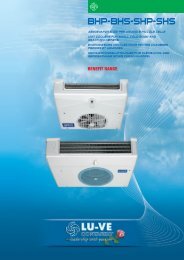
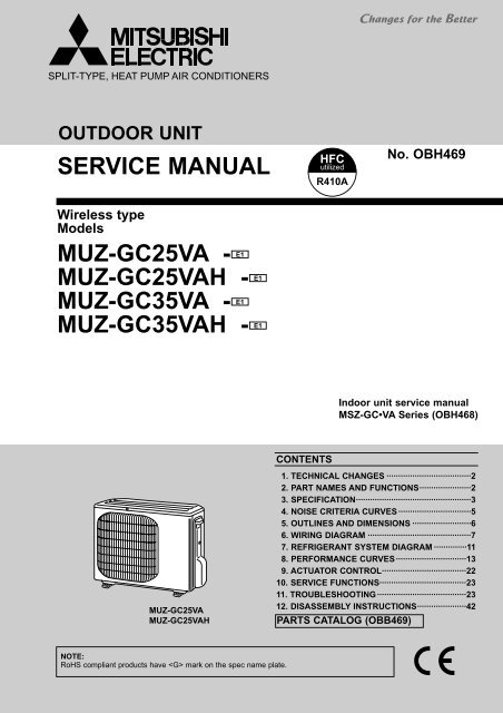
SPLIT-TYPE, HEAT PUMP AIR CONDITIONERSOUTDOOR UNITSERVICE MANUALWireless typeModelsE1MUZ-GC25VA -E1MUZ-GC25VAH -E1MUZ-GC35VA -MUZ-GC35VAH - E1HFCutilizedR410ANo. OBH469Indoor unit service manualMSZ-GC•VA Series (OBH468)MUZ-GC25VAMUZ-GC25VAHCONTENTS1. TECHNICAL CHANGES ····································22. PART NAMES AND FUNCTIONS······················23. SPECIFICATION·················································34. NOISE CRITERIA CURVES ·······························55. OUTLINES AND DIMENSIONS ·························66. WIRING DIAGRAM ············································77. REFRIGERANT SYSTEM DIAGRAM ··············118. PERFORMANCE CURVES ······························139. ACTUATOR CONTROL····································2210. SERVICE FUNCTIONS·····································2311. TROUBLESHOOTING······································2312. DISASSEMBLY INSTRUCTIONS·····················42PARTS CATALOG (OBB469)NOTE:RoHS compliant products have mark on the spec name plate.
1 TECHNICAL CHANGESMUZ-GA25VA - E3 ➔ MUZ-GC25VA - E1MUZ-GA25VAH - E3 ➔ MUZ-GC25VAH - E1MUZ-GA35VA - E3 ➔ MUZ-GC35VA - E1MUZ-GA35VAH - ➔ MUZ-GC35VAH - E11.Outdoor model has been changed.2PART NAMES AND FUNCTIONSMUZ-GC25VAMUZ-GC25VAHMUZ-GC35VAMUZ-GC35VAHAir inletAir inletPipingDrain hoseAir outletPipingDrain hoseAir outletDrain outletDrain outletACCESSORIES1 Drain socketMUZ-GC25VA1MUZ-GC35VA12
3 SPECIFICATIONOutdoor modelMUZ-GC25VAMUZ-GC25VAHMUZ-GC35VAMUZ-GC35VAHCapacityElectricaldataFunctionPower supplyCapacity Rated frequency(Min.-Max.)DehumidificationAir flow ✽1Power outletRunning current ✽1(Total)Power input ✽1(Total)Power factor ✽1(Total)Starting current ✽1(Total)Compressor motor current ✽1Fan motor current ✽1ModelOutputFan motor ModelDimensions WOHODWeightSound level ✽1Fan speedFan speed regulatorRefrigerant fillingcapacity(R410A)Refrigeration oil (Model)kWr/hK /hAAW%AAACoefficient of performance(C.O.P) ✽1(Total)CompressorSpecialremarksWmmkgdB(A)rpmkgccCooling2.5 (0.9-3.0)1.41,8123.6665804.23.14 3.740.243.76 3.83KNB065FDTH(C)500RA6V21-AB or BB684o540o255264681010.75HeatingSingle phase230V,50Hz3.2 (0.9-4.5)—1,7884.2835864780010320 (NEO22)Cooling3.5 (1.0-3.9)2.02,0105.01,075934.470.313.265.0KNB073FEDH or FGDH550RC0J50-AM800o550o2853147810/75020.85Heating4.0 (0.9-5.0)—2,0824.91,055944.330.353.7948880/810/6503NOTE : Test conditions are based on ISO 5151Cooling : Indoor Dry-bulb temperature 27:Wet-bulb temperature 19:Outdoor Dry-bulb temperature 35:Heating : Indoor Dry-bulb temperature 20:Outdoor Dry-bulb temperature 7: Wet-bulb temperature 6:Refrigerant piping length (one way): 5m✽1 Measured under rated operating frequency3
Specifications and rating conditions of main electric partsItemModelMUZ-GC25VAMUZ-GC25VAH MUZ-GC35VA MUZ-GC35VAHCurrent(CT)transformer (CT761, CT781)Smoothing(C61,C62)capacitor(C63A, C63B, C63C)Diode module(DB61)(DB65)(DB61, DB65)Fuse(F61)(F701, F801)(F71,F801,F901)Defrost heater(H)Intelligent power module (IPM)Expansion valve coil (LEV)Reactor(L61)Current-detecting(R61)resistor(R825,R831)Current-limiting PTC thermistor (PTC64)Current-limiting resistor (R64A, R64B)Terminal block(TB1,TB2)Relay(X61)(X63)(X64)(X66)R.V. coil(21S4)Heater protector(26H)Outdoor fan motor thermal fuseIGBT(TR821)20A—500+ 420V—15A 600V10A 600V—T20AL250VT3.15AL250V——230V 130W—10A 600VCAM-MD12ME 12VDC7A 18.0mH45m" 5W25m" 5W33"—3P2A 240V3A 250V20A 250V—3A 250V—SHF-4-10W5—Open 45:—Open 152: (RA6V21-AB) or Open 126: (RA6V21-BB)3A 600V20A—620+ 420V——25A 600V—T3.15AL250V230V 138W15A 600V10A 23.0mH—10" 5W—3A 250VSTF-01AJ503Open 45:—4
4 NOISE CRITERIA CURVESMUZ-GC25VAMUZ-GC25VAHMUZ-GC35VAMUZ-GC35VAHFUNCTION SPL(dB(A)) LINEFUNCTION SPL(dB(A)) LINECOOLING46COOLING47HEATING47HEATING489090OCTAVE BAND SOUND PRESSURE LEVEL, dB re 0.0002 MICRO BAR8070605040302010APPROXIMATETHRESHOLD OFHEARING FORCONTINUOUSNOISE63 125 250 500 1000 2000 4000 8000BAND CENTER FREQUENCIES, HzNC-70NC-60NC-50NC-40NC-30NC-20OCTAVE BAND SOUND PRESSURE LEVEL, dB re 0.0002 MICRO BAR8070605040302010APPROXIMATETHRESHOLD OFHEARING FORCONTINUOUSNOISE63 125 250 500 1000 2000 4000 8000BAND CENTER FREQUENCIES, HzNC-70NC-60NC-50NC-40NC-30NC-20Test conditionsCooling : Dry-bulb temperature 35:Heating : Dry-bulb temperature 7: Wet-bulb temperature 6:OUTDOOR UNIT1mMICROPHONE5
1027054022.5Bolt pitch forinstallation264~28030047.55OUTLINES AND DIMENSIONSMUZ-GC25VAMUZ-GC25VAHREQUIRED SPACEBasically open 100 mm or morewithout any obstruction in frontand on both sides of the unit.Unit: mm381.5Drain hole [33 (Only MUZ-GC25VA)100 mm or more100 mm or moreAir inAir in100 mm or more350 mm or more40Open two sides of left,right, or rear side.17.5Air out2 holes 10 X 1620.8255Service panelHandleLiquid refrigerant pipe jointRefrigerant pipe (flared) [6.35144.689.661Gas refrigerant pipe jointRefrigerant pipe (flared) [9.52105243500Bolt pitch for installation684Service port145.5MUZ-GC35VAMUZ-GC35VAHREQUIRED SPACEBasically open 100 mm or morewithout any obstruction in frontand on both sides of the unit.400Air inDrain hole [42 (MUZ-GC35VA)Drain hole [33 (MUZ-GC35VAH)100 mm or more100 mm or more344.528544Air inBolt pitch forinstallation304~325200 mm or more350 mm or more22.32 holes 10 X 21Air out4017.523Service panelOpen two sides of left,right, or rear side.HandleLiquid refrigerant pipe jointRefrigerant pipe (flared) [6.3555043-35-43-40-28010150302.569164.599.5170.5Service portGas refrigerant pipe jointRefrigerant pipe (flared) [9.52500 Bolt pitch for installation8006
6 WIRING DIAGRAMMUZ-GC25VA7
MUZ-GC25VAH8
MUZ-GC35VA9
MUZ-GC35VAH10
7 REFRIGERANT SYSTEM DIAGRAMMUZ-GC25VAMUZ-GC25VAHRefrigerant pipe [9.52(with heat insulator)Muffler4-way valveUnit:mmFlared connectionStop valve(with service port)DischargetemperaturethermistorRT62MufflerCompressorDefrostthermistorRT61OutdoorheatexchangerAmbienttemperaturethermistorRT65Flared connectionRefrigerant pipe [6.35(with heat insulator)Capillary tube[3.0✕[2.0✕260Stop valve(with strainer)ExpansionvalveStrainer#100R.V. coilheating ONcooling OFFRefrigerant flow in coolingRefrigerant flow in heatingMUZ-GC35VAMUZ-GC35VAHRefrigerant pipe [9.52(with heat insulator)Muffler4-way valveFlared connectionStop valve(with service port)DischargetemperaturethermistorRT62MufflerCompressorDefrostthermistorRT61OutdoorheatexchangerAmbienttemperaturethermistorRT65Flared connectionRefrigerant pipe [6.35(with heat insulator)Capillary tube[3.0✕[2.0✕240Stop valve(with strainer)ExpansionvalveMufflerStrainer#100R.V. coilheating ONcooling OFFRefrigerant flow in coolingRefrigerant flow in heating11
MAX. REFRIGERANT PIPING LENGTH and MAX. HEIGHT DIFFERENCEModelMUZ-GC25VAMUZ-GC25VAHMUZ-GC35VAMUZ-GC35VAHRefrigerant piping : mMax. lengthMax. Height differenceAB2012Piping size O.D : mmGasLiquid9.526.35IndoorunitMax. HeightdifferenceBMax. lengthAOutdoor unitADDITIONAL REFRIGERANT CHARGE (R410A:g)ModelMUZ-GC25VAMUZ-GC25VAHMUZ-GC35VAMUZ-GC35VAHOutdoor unitprecharged750850Refrigerant piping length (one way)5m 6m 7m 8m 9m 10m 11m 12m 13m 14m 15m 20m0 0 0 90 120 150 180 210 240 270 300 450Calculation : Xg=30 g/m ✕ (Refrigerant piping length (m)–5)NOTE: Refrigerant piping exceeding 7 m requires additional refrigerant charge according to the calculation.12
8 PERFORMANCE CURVESMUZ-GC25VAMUZ-GC25VAHMUZ-GC35VAMUZ-GC35VAHThe standard data contained in these specifications apply only to the operation of the air conditioner under normal conditions.Since operating conditions vary according to the areas where these units are installed, the following information has been providedto clarify the operating characteristics of the air conditioner under the conditions indicated by the performance curve.(1) GUARANTEED VOLTAGE198 ~ 264V, 50Hz(2) AIR FLOWAir flow should be set at MAX.(3) MAIN READINGS(1) Indoor intake air wet-bulb temperature : °C WB(2) Indoor outlet air wet-bulb temperature : °C WB(3) Outdoor intake air dry-bulb temperature : °C DB(4) Total input: W(5) Indoor intake air dry-bulb temperature : °C DB(6) Outdoor intake air wet-bulb temperature : °C WB(7) Total input : WIndoor air wet/dry-bulb temperature difference on the left side of the following chart shows the difference between theindoor intake air wet/dry-bulb temperature and the indoor outlet air wet/dry-bulb temperature for your reference at service.}}CoolingHeatingHow to measure the indoor air wet-bulb / dry-bulb temperature difference1. Attach at least 2 sets of wet and dry-bulb thermometers to the indoor air intake as shown in the figure, and at least 2 setsof wet and dry-bulb thermometers to the indoor air outlet. The thermometers must be attached to the position where airspeed is high.2. Attach at least 2 sets of wet and dry-bulb thermometers to the outdoor air intake.Cover the thermometers to prevent direct rays of the sun.3. Check that the air filter is cleaned.4. Open windows and doors of room.5. Press the EMERGENCY OPERATION switch once (twice) to start the EMERGENCY COOL (HEAT) MODE.6. When system stabilizes after more than 15 minutes, measure temperature and take an average temperature.7. 10 minutes later, measure temperature again and check that the temperature does not change.INDOOR UNITOUTDOOR UNITWet and dry-bulbthermometersWet and dry-bulbthermometers8-1. Capacity and input curvesIndoor air Wet-bulb temperaturedifference (degree)8.17.56.86.35.75.14.5MUZ-GC25VAMUZ-GC25VAHat Rated frequency12.711.610.69.68.77.86.9MUZ-GC35VAMUZ-GC35VAHCapacity correction factor1.51.41.31.21.1Cooling capacityIndoor intake air Wet-bulb temperature (:)1.0220.9201818 20 25 30 35 40 46262413
Indoor air Wet-bulb temperaturedifference (degree)6.86.35.75.14.54.0MUZ-GC25VAMUZ-GC25VAHat Rated frequency10.69.68.77.86.96.0MUZ-GC35VAMUZ-GC35VAHat Rated frequency input correction factor1.31.21.11.00.90.8Total input (cooling)26 24Indoor intake air Wet-bulb temperature (:)18 20 25 30 35 40 46Outdoor intake air Dry-bulb temperature (:)222018Indoor air Dry-bulb temperaturedifference (degree)20.919.317.716.114.512.911.39.78.06.427.525.423.321.219.116.914.812.710.68.5Capacity correction factor1.31.21.11.00.90.80.70.60.50.4Heating capacityIndoor intake air Dry-bulb temperature (:)152026MUZ-GC25VAMUZ-GC25VAHat Rated frequencyMUZ-GC35VAMUZ-GC35VAHat Rated frequency-20 -15 -10 -5 0 5 10 15Outdoor intake air Wet-bulb temperature (:)Indoor air Dry-bulb temperaturedifference (degree)20.919.317.716.114.512.911.39.78.06.427.525.423.321.219.116.914.812.710.68.5Input correction factor1.31.21.11.00.90.80.70.60.50.4Total input(heating)Indoor intake air Dry-bulb temperature (:)261520MUZ-GC25VAMUZ-GC25VAHat Rated frequencyMUZ-GC35VAMUZ-GC35VAHat Rated frequency-20 -15 -10 -5 0 5 10 15Outdoor intake air Wet-bulb temperature (:)NOTE:The above broken lines are for the heating operation without any frost anddefrost operation.14
8-2. Capacity and input correction by operational frequency of compressorMUZ-GC25VAMUZ-GC25VAHCapacity correction factorsCorrection of Cooling capacity Correction of Cooling total input1.51.51.00.5Input correction factors1.00.5Capacity correction factorsCorrection of Heating capacity2.01.51.00.5Correction of Heating total input2.01.51.00.50.00.00.00.00 50 100 150(Hz) 0 50 100 150(Hz) 0 50 100 150(Hz) 0 50 100 150(Hz)The operational frequency of compressor The operational frequency of compressor The operational frequency of compressor The operational frequency of compressorInput correction factorsMUZ-GC35VAMUZ-GC35VAHCorrection of Cooling capacity1.5Correction of Cooling total input1.5Correction of Heating capacity2.0Correction of Heating total input2.0Capacity correction factors1.00.5Input correction factors1.00.5Capacity correction factors1.51.00.50.00.00.00.00 50 100 150(Hz) 0 50 100 150(Hz) 0 50 100 150(Hz) 0 50 100 150(Hz)The operational frequency of compressor The operational frequency of compressor The operational frequency of compressor The operational frequency of compressorInput correction factors1.51.00.58-3. Test run operation (How to operate fixed-frequency operation)1. Press EMERGENCY OPERATION switch to COOL or HEAT mode (COOL : Press once, HEAT : Press twice).2. Test run operation starts and continues to operate for 30 minutes.3. Compressor operates at rated frequency in COOL mode or 58Hz in HEAT mode.4. Indoor fan operates at High speed.5. After 30 minutes, test run operation finishes and EMERGENCY OPERATION starts (Operation frequency of compressorvaries).6. To cancel test run operation (EMERGENCY OPERATION), press EMERGENCY OPERATION switch or any button onremote controller.15
8-4. Outdoor low pressure and outdoor unit currentCOOL operation1 Both indoor and outdoor unit are under thesame temperature/humidity condition.2 Operation : TEST RUN OPERATION (refer to 8-3.)Dry-bulb temperature(:) Relative humidity(%)20 5025 6030 70Outdoor low pressureMUZ-GC25VAMUZ-GC25VAHkgf/F [Gauge]14 1.41210864MPa [Gauge]1.21.00.80.60.4MUZ-GC35VAMUZ-GC35VAHkgf/F [Gauge]14 1.41210864MPa [Gauge]1.21.00.80.60.4NOTE :The unit of pressure has beenchanged to MPa on the internationalsystem of units (SI unit system).The conversion factor is:1(MPa [Gauge]) =10.2(kgf/f[Gauge])20.215 18 20 25 30 32 35(˚C)50 60 70 (%)Ambient temperature(˚C)Ambient humidity(%)Outdoor unit currentMUZ-GC25VAMUZ-GC25VAH(A)42MUZ-GC35VAMUZ-GC35VAH(A) 60.215 18 20 25 30 32 35(˚C)50 60 70 (%)Ambient temperature(˚C)Ambient humidity(%)3.55342.53215 18 2050256030 327035(˚C)(%)Ambient temperature(˚C)Ambient humidity(%)215 18 2050256030 327035(˚C)(%)Ambient temperature(˚C)Ambient humidity(%)HEAT operation1 Condition :Dry bulb temperature (°C)Wet bulb temperature (°C)Indoor20.014.521Outdoor7 156 1220.014.52 Operation : Test run operation (refer to 8-3.)Outdoor unit currentMUZ-GC25VAMUZ-GC25VAH(A) 3.02.52.01.51.00.5MUZ-GC35VAMUZ-GC35VAH(A) 3.02.52.01.51.00.50.02 5 10 15 20 25(:)Ambient temperature(˚C)0.02 5 10 15 20 25(:)Ambient temperature(˚C)16
PERFORMANCE DATA COOL operation at Rated frequencyMUZ-GC25VA MUZ-GC25VAHCAPACITY:2.5(kW) SHF:0.79 INPUT:665(W)OUTDOOR DB(:)INDOOR INDOOR2125 27 30DB(:) WB(:) Q SHC SHF INPUT Q SHC SHF INPUT Q SHC SHF INPUT Q SHC SHF INPUT21 18 2.94 1.79 0.61 532 2.81 1.72 0.61 559 2.70 1.65 0.61 585 2.60 1.59 0.61 61221 20 3.06 1.50 0.49 559 2.94 1.44 0.49 592 2.85 1.40 0.49 605 2.75 1.35 0.49 63222 18 2.94 1.91 0.65 532 2.81 1.83 0.65 559 2.70 1.76 0.65 585 2.60 1.69 0.65 61222 20 3.06 1.62 0.53 559 2.94 1.56 0.53 592 2.85 1.51 0.53 605 2.75 1.46 0.53 63222 22 3.19 1.31 0.41 579 3.08 1.26 0.41 615 3.00 1.23 0.41 632 2.88 1.18 0.41 65823 18 2.94 2.03 0.69 532 2.81 1.94 0.69 559 2.70 1.86 0.69 585 2.60 1.79 0.69 61223 20 3.06 1.75 0.57 559 2.94 1.67 0.57 592 2.85 1.62 0.57 605 2.75 1.57 0.57 63223 22 3.19 1.43 0.45 579 3.08 1.38 0.45 615 3.00 1.35 0.45 632 2.88 1.29 0.45 65824 18 2.94 2.14 0.73 532 2.81 2.05 0.73 559 2.70 1.97 0.73 585 2.60 1.90 0.73 61224 20 3.06 1.87 0.61 559 2.94 1.79 0.61 592 2.85 1.74 0.61 605 2.75 1.68 0.61 63224 22 3.19 1.56 0.49 579 3.08 1.51 0.49 615 3.00 1.47 0.49 632 2.88 1.41 0.49 65824 24 3.35 1.24 0.37 605 3.23 1.19 0.37 638 3.15 1.17 0.37 658 3.05 1.13 0.37 69225 18 2.94 2.26 0.77 532 2.81 2.17 0.77 559 2.70 2.08 0.77 585 2.60 2.00 0.77 61225 20 3.06 1.99 0.65 559 2.94 1.91 0.65 592 2.85 1.85 0.65 605 2.75 1.79 0.65 63225 22 3.19 1.69 0.53 579 3.08 1.63 0.53 615 3.00 1.59 0.53 632 2.88 1.52 0.53 65825 24 3.35 1.37 0.41 605 3.23 1.32 0.41 638 3.15 1.29 0.41 658 3.05 1.25 0.41 69226 18 2.94 2.38 0.81 532 2.81 2.28 0.81 559 2.70 2.19 0.81 585 2.60 2.11 0.81 61226 20 3.06 2.11 0.69 559 2.94 2.03 0.69 592 2.85 1.97 0.69 605 2.75 1.90 0.69 63226 22 3.19 1.82 0.57 579 3.08 1.75 0.57 615 3.00 1.71 0.57 632 2.88 1.64 0.57 65826 24 3.35 1.51 0.45 605 3.23 1.45 0.45 638 3.15 1.42 0.45 658 3.05 1.37 0.45 69226 26 3.45 1.14 0.33 638 3.35 1.11 0.33 672 3.30 1.09 0.33 692 3.20 1.06 0.33 71227 18 2.94 2.50 0.85 532 2.81 2.39 0.85 559 2.70 2.30 0.85 585 2.60 2.21 0.85 61227 20 3.06 2.24 0.73 559 2.94 2.14 0.73 592 2.85 2.08 0.73 605 2.75 2.01 0.73 63227 22 3.19 1.94 0.61 579 3.08 1.88 0.61 615 3.00 1.83 0.61 632 2.88 1.75 0.61 65827 24 3.35 1.64 0.49 605 3.23 1.58 0.49 638 3.15 1.54 0.49 658 3.05 1.49 0.49 69227 26 3.45 1.28 0.37 638 3.35 1.24 0.37 672 3.30 1.22 0.37 692 3.20 1.18 0.37 71228 18 2.94 2.61 0.89 532 2.81 2.50 0.89 559 2.70 2.40 0.89 585 2.60 2.31 0.89 61228 20 3.06 2.36 0.77 559 2.94 2.26 0.77 592 2.85 2.19 0.77 605 2.75 2.12 0.77 63228 22 3.19 2.07 0.65 579 3.08 2.00 0.65 615 3.00 1.95 0.65 632 2.88 1.87 0.65 65828 24 3.35 1.78 0.53 605 3.23 1.71 0.53 638 3.15 1.67 0.53 658 3.05 1.62 0.53 69228 26 3.45 1.41 0.41 638 3.35 1.37 0.41 672 3.30 1.35 0.41 692 3.20 1.31 0.41 71229 18 2.94 2.73 0.93 532 2.81 2.62 0.93 559 2.70 2.51 0.93 585 2.60 2.42 0.93 61229 20 3.06 2.48 0.81 559 2.94 2.38 0.81 592 2.85 2.31 0.81 605 2.75 2.23 0.81 63229 22 3.19 2.20 0.69 579 3.08 2.12 0.69 615 3.00 2.07 0.69 632 2.88 1.98 0.69 65829 24 3.35 1.91 0.57 605 3.23 1.84 0.57 638 3.15 1.80 0.57 658 3.05 1.74 0.57 69229 26 3.45 1.55 0.45 638 3.35 1.51 0.45 672 3.30 1.49 0.45 692 3.20 1.44 0.45 71230 18 2.94 2.85 0.97 532 2.81 2.73 0.97 559 2.70 2.62 0.97 585 2.60 2.52 0.97 61230 20 3.06 2.60 0.85 559 2.94 2.50 0.85 592 2.85 2.42 0.85 605 2.75 2.34 0.85 63230 22 3.19 2.33 0.73 579 3.08 2.24 0.73 615 3.00 2.19 0.73 632 2.88 2.10 0.73 65830 24 3.35 2.04 0.61 605 3.23 1.97 0.61 638 3.15 1.92 0.61 658 3.05 1.86 0.61 69230 26 3.45 1.69 0.49 638 3.35 1.64 0.49 672 3.30 1.62 0.49 692 3.20 1.57 0.49 71231 18 2.94 2.97 1.01 532 2.81 2.84 1.01 559 2.70 2.73 1.01 585 2.60 2.63 1.01 61231 20 3.06 2.73 0.89 559 2.94 2.61 0.89 592 2.85 2.54 0.89 605 2.75 2.45 0.89 63231 22 3.19 2.45 0.77 579 3.08 2.37 0.77 615 3.00 2.31 0.77 632 2.88 2.21 0.77 65831 24 3.35 2.18 0.65 605 3.23 2.10 0.65 638 3.15 2.05 0.65 658 3.05 1.98 0.65 69231 26 3.45 1.83 0.53 638 3.35 1.78 0.53 672 3.30 1.75 0.53 692 3.20 1.70 0.53 71232 18 2.94 3.08 1.05 532 2.81 2.95 1.05 559 2.70 2.84 1.05 585 2.60 2.73 1.05 61232 20 3.06 2.85 0.93 559 2.94 2.73 0.93 592 2.85 2.65 0.93 605 2.75 2.56 0.93 63232 22 3.19 2.58 0.81 579 3.08 2.49 0.81 615 3.00 2.43 0.81 632 2.88 2.33 0.81 65832 24 3.35 2.31 0.69 605 3.23 2.23 0.69 638 3.15 2.17 0.69 658 3.05 2.10 0.69 69232 26 3.45 1.97 0.57 638 3.35 1.91 0.57 672 3.30 1.88 0.57 692 3.20 1.82 0.57 712NOTE: Q : Total capacity (kW) SHF : Sensible heat factor DB : Dry-bulb temperatureSHC : Sensible heat capacity (kW) INPUT : Total power input (W) WB : Wet-bulb temperature17
PERFORMANCE DATA COOL operation at Rated frequencyMUZ-GC25VA MUZ-GC25VAHCAPACITY:2.5(kW)OUTDOOR DB(:)INDOOR INDOOR35 40 46DB (:) WB (:) Q SHC SHF INPUT Q SHC SHF INPUT Q SHC SHF INPUT21 1821 2022 1822 2022 2223 1823 2023 2224 1824 2024 2224 2425 1825 2025 2225 2426 1826 2026 2226 2426 2627 1827 2027 2227 2427 2628 1828 2028 2228 2428 2629 1829 2029 2229 2429 2630 1830 2030 2230 2430 2631 1831 2031 2231 2431 2632 1832 2032 2232 2432 26SHF:0.79INPUT:665(W)2.45 1.49 0.61 652 2.25 1.37 0.61 692 2.08 1.27 0.61 7182.58 1.26 0.49 678 2.40 1.18 0.49 712 2.23 1.09 0.49 7512.45 1.59 0.65 652 2.25 1.46 0.65 692 2.08 1.35 0.65 7182.58 1.36 0.53 678 2.40 1.27 0.53 712 2.23 1.18 0.53 7512.73 1.12 0.41 705 2.55 1.05 0.41 745 2.38 0.97 0.41 7712.45 1.69 0.69 652 2.25 1.55 0.69 692 2.08 1.43 0.69 7182.58 1.47 0.57 678 2.40 1.37 0.57 712 2.23 1.27 0.57 7512.73 1.23 0.45 705 2.55 1.15 0.45 745 2.38 1.07 0.45 7712.45 1.79 0.73 652 2.25 1.64 0.73 692 2.08 1.51 0.73 7182.58 1.57 0.61 678 2.40 1.46 0.61 712 2.23 1.36 0.61 7512.73 1.34 0.49 705 2.55 1.25 0.49 745 2.38 1.16 0.49 7712.88 1.06 0.37 732 2.70 1.00 0.37 765 2.55 0.94 0.37 7982.45 1.89 0.77 652 2.25 1.73 0.77 692 2.08 1.60 0.77 7182.58 1.67 0.65 678 2.40 1.56 0.65 712 2.23 1.45 0.65 7512.73 1.44 0.53 705 2.55 1.35 0.53 745 2.38 1.26 0.53 7712.88 1.18 0.41 732 2.70 1.11 0.41 765 2.55 1.05 0.41 7982.45 1.98 0.81 652 2.25 1.82 0.81 692 2.08 1.68 0.81 7182.58 1.78 0.69 678 2.40 1.66 0.69 712 2.23 1.54 0.69 7512.73 1.55 0.57 705 2.55 1.45 0.57 745 2.38 1.35 0.57 7712.88 1.29 0.45 732 2.70 1.22 0.45 765 2.55 1.15 0.45 7983.03 1.00 0.33 758 2.85 0.94 0.33 791 2.68 0.88 0.33 8252.45 2.08 0.85 652 2.25 1.91 0.85 692 2.08 1.76 0.85 7182.58 1.88 0.73 678 2.40 1.75 0.73 712 2.23 1.62 0.73 7512.73 1.66 0.61 705 2.55 1.56 0.61 745 2.38 1.45 0.61 7712.88 1.41 0.49 732 2.70 1.32 0.49 765 2.55 1.25 0.49 7983.03 1.12 0.37 758 2.85 1.05 0.37 791 2.68 0.99 0.37 8252.45 2.18 0.89 652 2.25 2.00 0.89 692 2.08 1.85 0.89 7182.58 1.98 0.77 678 2.40 1.85 0.77 712 2.23 1.71 0.77 7512.73 1.77 0.65 705 2.55 1.66 0.65 745 2.38 1.54 0.65 7712.88 1.52 0.53 732 2.70 1.43 0.53 765 2.55 1.35 0.53 7983.03 1.24 0.41 758 2.85 1.17 0.41 791 2.68 1.10 0.41 8252.45 2.28 0.93 652 2.25 2.09 0.93 692 2.08 1.93 0.93 7182.58 2.09 0.81 678 2.40 1.94 0.81 712 2.23 1.80 0.81 7512.73 1.88 0.69 705 2.55 1.76 0.69 745 2.38 1.64 0.69 7712.88 1.64 0.57 732 2.70 1.54 0.57 765 2.55 1.45 0.57 7983.03 1.36 0.45 758 2.85 1.28 0.45 791 2.68 1.20 0.45 8252.45 2.38 0.97 652 2.25 2.18 0.97 692 2.08 2.01 0.97 7182.58 2.19 0.85 678 2.40 2.04 0.85 712 2.23 1.89 0.85 7512.73 1.99 0.73 705 2.55 1.86 0.73 745 2.38 1.73 0.73 7712.88 1.75 0.61 732 2.70 1.65 0.61 765 2.55 1.56 0.61 7983.03 1.48 0.49 758 2.85 1.40 0.49 791 2.68 1.31 0.49 8252.45 2.47 1.01 652 2.25 2.27 1.01 692 2.08 2.10 1.01 7182.58 2.29 0.89 678 2.40 2.14 0.89 712 2.23 1.98 0.89 7512.73 2.10 0.77 705 2.55 1.96 0.77 745 2.38 1.83 0.77 7712.88 1.87 0.65 732 2.70 1.76 0.65 765 2.55 1.66 0.65 7983.03 1.60 0.53 758 2.85 1.51 0.53 791 2.68 1.42 0.53 8252.45 2.57 1.05 652 2.25 2.36 1.05 692 2.08 2.18 1.05 7182.58 2.39 0.93 678 2.40 2.23 0.93 712 2.23 2.07 0.93 7512.73 2.21 0.81 705 2.55 2.07 0.81 745 2.38 1.92 0.81 7712.88 1.98 0.69 732 2.70 1.86 0.69 765 2.55 1.76 0.69 7983.03 1.72 0.57 758 2.85 1.62 0.57 791 2.68 1.52 0.57 825NOTE: Q : Total capacity (kW) SHF : Sensible heat factor DB : Dry-bulb temperatureSHC : Sensible heat capacity (kW) INPUT : Total power input (W) WB : Wet-bulb temperature18
PERFORMANCE DATA COOL operation at Rated frequencyMUZ-GC35VA MUZ-GC35VAHCAPACITY:3.5(kW) SHF:0.76 INPUT:1075(W)OUTDOOR DB(:)INDOOR INDOOR2125 27 30DB(:) WB(:) Q SHC SHF INPUT Q SHC SHF INPUT Q SHC SHF INPUT Q SHC SHF INPUT21 1821 2022 1822 2022 2223 1823 2023 2224 1824 2024 2224 2425 1825 2025 2225 2426 1826 2026 2226 2426 2627 1827 2027 2227 2427 2628 1828 2028 2228 2428 2629 1829 2029 2229 2429 2630 1830 2030 2230 2430 2631 1831 2031 2231 2431 2632 1832 2032 2232 2432 264.11 2.39 0.58 860 3.94 2.28 0.58 903 3.78 2.19 0.58 946 3.64 2.11 0.58 9894.29 1.97 0.46 903 4.11 1.89 0.46 957 3.99 1.84 0.46 978 3.85 1.77 0.46 10214.11 2.55 0.62 860 3.94 2.44 0.62 903 3.78 2.34 0.62 946 3.64 2.26 0.62 9894.29 2.14 0.50 903 4.11 2.06 0.50 957 3.99 2.00 0.50 978 3.85 1.93 0.50 10214.46 1.70 0.38 935 4.31 1.64 0.38 994 4.20 1.60 0.38 1021 4.03 1.53 0.38 10644.11 2.71 0.66 860 3.94 2.60 0.66 903 3.78 2.49 0.66 946 3.64 2.40 0.66 9894.29 2.32 0.54 903 4.11 2.22 0.54 957 3.99 2.15 0.54 978 3.85 2.08 0.54 10214.46 1.87 0.42 935 4.31 1.81 0.42 994 4.20 1.76 0.42 1021 4.03 1.69 0.42 10644.11 2.88 0.70 860 3.94 2.76 0.70 903 3.78 2.65 0.70 946 3.64 2.55 0.70 9894.29 2.49 0.58 903 4.11 2.39 0.58 957 3.99 2.31 0.58 978 3.85 2.23 0.58 10214.46 2.05 0.46 935 4.31 1.98 0.46 994 4.20 1.93 0.46 1021 4.03 1.85 0.46 10644.69 1.59 0.34 978 4.52 1.54 0.34 1032 4.41 1.50 0.34 1064 4.27 1.45 0.34 11184.11 3.04 0.74 860 3.94 2.91 0.74 903 3.78 2.80 0.74 946 3.64 2.69 0.74 9894.29 2.66 0.62 903 4.11 2.55 0.62 957 3.99 2.47 0.62 978 3.85 2.39 0.62 10214.46 2.23 0.50 935 4.31 2.15 0.50 994 4.20 2.10 0.50 1021 4.03 2.01 0.50 10644.69 1.78 0.38 978 4.52 1.72 0.38 1032 4.41 1.68 0.38 1064 4.27 1.62 0.38 11184.11 3.21 0.78 860 3.94 3.07 0.78 903 3.78 2.95 0.78 946 3.64 2.84 0.78 9894.29 2.83 0.66 903 4.11 2.71 0.66 957 3.99 2.63 0.66 978 3.85 2.54 0.66 10214.46 2.41 0.54 935 4.31 2.32 0.54 994 4.20 2.27 0.54 1021 4.03 2.17 0.54 10644.69 1.97 0.42 978 4.52 1.90 0.42 1032 4.41 1.85 0.42 1064 4.27 1.79 0.42 11184.83 1.45 0.30 1032 4.69 1.41 0.30 1086 4.62 1.39 0.30 1118 4.48 1.34 0.30 11504.11 3.37 0.82 860 3.94 3.23 0.82 903 3.78 3.10 0.82 946 3.64 2.98 0.82 9894.29 3.00 0.70 903 4.11 2.88 0.70 957 3.99 2.79 0.70 978 3.85 2.70 0.70 10214.46 2.59 0.58 935 4.31 2.50 0.58 994 4.20 2.44 0.58 1021 4.03 2.33 0.58 10644.69 2.16 0.46 978 4.52 2.08 0.46 1032 4.41 2.03 0.46 1064 4.27 1.96 0.46 11184.83 1.64 0.34 1032 4.69 1.59 0.34 1086 4.62 1.57 0.34 1118 4.48 1.52 0.34 11504.11 3.54 0.86 860 3.94 3.39 0.86 903 3.78 3.25 0.86 946 3.64 3.13 0.86 9894.29 3.17 0.74 903 4.11 3.04 0.74 957 3.99 2.95 0.74 978 3.85 2.85 0.74 10214.46 2.77 0.62 935 4.31 2.67 0.62 994 4.20 2.60 0.62 1021 4.03 2.50 0.62 10644.69 2.35 0.50 978 4.52 2.26 0.50 1032 4.41 2.21 0.50 1064 4.27 2.14 0.50 11184.83 1.84 0.38 1032 4.69 1.78 0.38 1086 4.62 1.76 0.38 1118 4.48 1.70 0.38 11504.11 3.70 0.90 860 3.94 3.54 0.90 903 3.78 3.40 0.90 946 3.64 3.28 0.90 9894.29 3.34 0.78 903 4.11 3.21 0.78 957 3.99 3.11 0.78 978 3.85 3.00 0.78 10214.46 2.95 0.66 935 4.31 2.84 0.66 994 4.20 2.77 0.66 1021 4.03 2.66 0.66 10644.69 2.53 0.54 978 4.52 2.44 0.54 1032 4.41 2.38 0.54 1064 4.27 2.31 0.54 11184.83 2.03 0.42 1032 4.69 1.97 0.42 1086 4.62 1.94 0.42 1118 4.48 1.88 0.42 11504.11 3.87 0.94 860 3.94 3.70 0.94 903 3.78 3.55 0.94 946 3.64 3.42 0.94 9894.29 3.52 0.82 903 4.11 3.37 0.82 957 3.99 3.27 0.82 978 3.85 3.16 0.82 10214.46 3.12 0.70 935 4.31 3.01 0.70 994 4.20 2.94 0.70 1021 4.03 2.82 0.70 10644.69 2.72 0.58 978 4.52 2.62 0.58 1032 4.41 2.56 0.58 1064 4.27 2.48 0.58 11184.83 2.22 0.46 1032 4.69 2.16 0.46 1086 4.62 2.13 0.46 1118 4.48 2.06 0.46 11504.11 4.03 0.98 860 3.94 3.86 0.98 903 3.78 3.70 0.98 946 3.64 3.57 0.98 9894.29 3.69 0.86 903 4.11 3.54 0.86 957 3.99 3.43 0.86 978 3.85 3.31 0.86 10214.46 3.30 0.74 935 4.31 3.19 0.74 994 4.20 3.11 0.74 1021 4.03 2.98 0.74 10644.69 2.91 0.62 978 4.52 2.80 0.62 1032 4.41 2.73 0.62 1064 4.27 2.65 0.62 11184.83 2.42 0.50 1032 4.69 2.35 0.50 1086 4.62 2.31 0.50 1118 4.48 2.24 0.50 11504.11 4.19 1.02 860 3.94 4.02 1.02 903 3.78 3.86 1.02 946 3.64 3.71 1.02 9894.29 3.86 0.90 903 4.11 3.70 0.90 957 3.99 3.59 0.90 978 3.85 3.47 0.90 10214.46 3.48 0.78 935 4.31 3.36 0.78 994 4.20 3.28 0.78 1021 4.03 3.14 0.78 10644.69 3.10 0.66 978 4.52 2.98 0.66 1032 4.41 2.91 0.66 1064 4.27 2.82 0.66 11184.83 2.61 0.54 1032 4.69 2.53 0.54 1086 4.62 2.49 0.54 1118 4.48 2.42 0.54 1150NOTE: Q : Total capacity (kW) SHF : Sensible heat factor DB : Dry-bulb temperatureSHC : Sensible heat capacity (kW) INPUT : Total power input (W) WB : Wet-bulb temperature19
PERFORMANCE DATA COOL operation at Rated frequencyMUZ-GC35VA MUZ-GC35VAHCAPACITY:3.5(kW)OUTDOOR DB(:)INDOOR INDOOR35 40 46DB (:) WB (:) Q SHC SHF INPUT Q SHC SHF INPUT Q SHC SHF INPUT21 1821 2022 1822 2022 2223 1823 2023 2224 1824 2024 2224 2425 1825 2025 2225 2426 1826 2026 2226 2426 2627 1827 2027 2227 2427 2628 1828 2028 2228 2428 2629 1829 2029 2229 2429 2630 1830 2030 2230 2430 2631 1831 2031 2231 2431 2632 1832 2032 2232 2432 26SHF:0.76INPUT:1075(W)3.43 1.99 0.58 1054 3.15 1.83 0.58 1118 2.91 1.68 0.58 11613.61 1.66 0.46 1097 3.36 1.55 0.46 1150 3.12 1.43 0.46 12153.43 2.13 0.62 1054 3.15 1.95 0.62 1118 2.91 1.80 0.62 11613.61 1.80 0.50 1097 3.36 1.68 0.50 1150 3.12 1.56 0.50 12153.82 1.45 0.38 1140 3.57 1.36 0.38 1204 3.33 1.26 0.38 12473.43 2.26 0.66 1054 3.15 2.08 0.66 1118 2.91 1.92 0.66 11613.61 1.95 0.54 1097 3.36 1.81 0.54 1150 3.12 1.68 0.54 12153.82 1.60 0.42 1140 3.57 1.50 0.42 1204 3.33 1.40 0.42 12473.43 2.40 0.70 1054 3.15 2.21 0.70 1118 2.91 2.03 0.70 11613.61 2.09 0.58 1097 3.36 1.95 0.58 1150 3.12 1.81 0.58 12153.82 1.75 0.46 1140 3.57 1.64 0.46 1204 3.33 1.53 0.46 12474.03 1.37 0.34 1183 3.78 1.29 0.34 1236 3.57 1.21 0.34 12903.43 2.54 0.74 1054 3.15 2.33 0.74 1118 2.91 2.15 0.74 11613.61 2.24 0.62 1097 3.36 2.08 0.62 1150 3.12 1.93 0.62 12153.82 1.91 0.50 1140 3.57 1.79 0.50 1204 3.33 1.66 0.50 12474.03 1.53 0.38 1183 3.78 1.44 0.38 1236 3.57 1.36 0.38 12903.43 2.68 0.78 1054 3.15 2.46 0.78 1118 2.91 2.27 0.78 11613.61 2.38 0.66 1097 3.36 2.22 0.66 1150 3.12 2.06 0.66 12153.82 2.06 0.54 1140 3.57 1.93 0.54 1204 3.33 1.80 0.54 12474.03 1.69 0.42 1183 3.78 1.59 0.42 1236 3.57 1.50 0.42 12904.24 1.27 0.30 1226 3.99 1.20 0.30 1279 3.75 1.12 0.30 13333.43 2.81 0.82 1054 3.15 2.58 0.82 1118 2.91 2.38 0.82 11613.61 2.52 0.70 1097 3.36 2.35 0.70 1150 3.12 2.18 0.70 12153.82 2.21 0.58 1140 3.57 2.07 0.58 1204 3.33 1.93 0.58 12474.03 1.85 0.46 1183 3.78 1.74 0.46 1236 3.57 1.64 0.46 12904.24 1.44 0.34 1226 3.99 1.36 0.34 1279 3.75 1.27 0.34 13333.43 2.95 0.86 1054 3.15 2.71 0.86 1118 2.91 2.50 0.86 11613.61 2.67 0.74 1097 3.36 2.49 0.74 1150 3.12 2.31 0.74 12153.82 2.37 0.62 1140 3.57 2.21 0.62 1204 3.33 2.06 0.62 12474.03 2.01 0.50 1183 3.78 1.89 0.50 1236 3.57 1.79 0.50 12904.24 1.61 0.38 1226 3.99 1.52 0.38 1279 3.75 1.42 0.38 13333.43 3.09 0.90 1054 3.15 2.84 0.90 1118 2.91 2.61 0.90 11613.61 2.81 0.78 1097 3.36 2.62 0.78 1150 3.12 2.43 0.78 12153.82 2.52 0.66 1140 3.57 2.36 0.66 1204 3.33 2.19 0.66 12474.03 2.17 0.54 1183 3.78 2.04 0.54 1236 3.57 1.93 0.54 12904.24 1.78 0.42 1226 3.99 1.68 0.42 1279 3.75 1.57 0.42 13333.43 3.22 0.94 1054 3.15 2.96 0.94 1118 2.91 2.73 0.94 11613.61 2.96 0.82 1097 3.36 2.76 0.82 1150 3.12 2.55 0.82 12153.82 2.67 0.70 1140 3.57 2.50 0.70 1204 3.33 2.33 0.70 12474.03 2.33 0.58 1183 3.78 2.19 0.58 1236 3.57 2.07 0.58 12904.24 1.95 0.46 1226 3.99 1.84 0.46 1279 3.75 1.72 0.46 13333.43 3.36 0.98 1054 3.15 3.09 0.98 1118 2.91 2.85 0.98 11613.61 3.10 0.86 1097 3.36 2.89 0.86 1150 3.12 2.68 0.86 12153.82 2.82 0.74 1140 3.57 2.64 0.74 1204 3.33 2.46 0.74 12474.03 2.50 0.62 1183 3.78 2.34 0.62 1236 3.57 2.21 0.62 12904.24 2.12 0.50 1226 3.99 2.00 0.50 1279 3.75 1.87 0.50 13333.43 3.50 1.02 1054 3.15 3.21 1.02 1118 2.91 2.96 1.02 11613.61 3.24 0.90 1097 3.36 3.02 0.90 1150 3.12 2.80 0.90 12153.82 2.98 0.78 1140 3.57 2.78 0.78 1204 3.33 2.59 0.78 12474.03 2.66 0.66 1183 3.78 2.49 0.66 1236 3.57 2.36 0.66 12904.24 2.29 0.54 1226 3.99 2.15 0.54 1279 3.75 2.02 0.54 1333NOTE: Q : Total capacity (kW) SHF : Sensible heat factor DB : Dry-bulb temperatureSHC : Sensible heat capacity (kW) INPUT : Total power input (W) WB : Wet-bulb temperature20
PERFORMANCE DATA HEAT operation at Rated frequencyMUZ-GC25VAMUZ-GC25VAHCAPACITY:3.2(kW) INPUT:835(W)OUTDOOR WB(:)INDOOR -10 -5 0 5 10 15 20DB(:) Q INPUT Q INPUT Q INPUT Q INPUT Q INPUT Q INPUT Q INPUT15 2.02 543 2.43 651 2.85 735 3.26 793 3.68 843 4.06 868 4.48 88521 1.92 585 2.30 693 2.72 768 3.10 827 3.52 868 3.90 893 4.30 92726 1.73 626 2.14 735 2.53 810 2.94 868 3.36 910 3.74 935 4.16 960MUZ-GC35VAMUZ-GC35VAHCAPACITY:4.0(kW) INPUT:1055(W)OUTDOOR WB(:)INDOOR -10 -5 0 5 10 15 20DB(:) Q INPUT Q INPUT Q INPUT Q INPUT Q INPUT Q INPUT Q INPUT15 2.52 686 3.04 823 3.56 928 4.08 1002 4.60 1066 5.08 1097 5.60 111821 2.40 739 2.88 876 3.40 971 3.88 1044 4.40 1097 4.88 1129 5.38 117126 2.16 791 2.68 928 3.16 1023 3.68 1097 4.20 1150 4.68 1182 5.20 1213NOTE:Q:Total capacity (kW) INPUT:Total power input (W) DB : Dry-bulb temperature WB : Wet-bulb temperature21
9 ACTUATOR CONTROLMUZ-GC25VA MUZ-GC35VAMUZ-GC25VAH MUZ-GC35VAH9-1. Outdoor fan motor controlThe fan motor turns ON/OFF, interlocking with the compressor.[ON] The fan motor turns ON 5 seconds before the compressor starts up.[OFF] The fan motor turns OFF 15 seconds after the compressor has stopped running.CompressorOutdoor fanmotorONOFFONOFF5 seconds 15 seconds9-2. R.V. coil controlHeating . . . . . . . . . . . . . . . . ONCooling . . . . . . . . . . . . . . . . OFFDry. . . . . . . . . . . . . . . . . . . . OFFNOTE: The 4-way valve reverses for 5 seconds right before start-up of the compressor.5 seconds5 secondsONCompressorOFFR.V.coilONOFFOutdoor fan ONmotor OFF9-3. Relation between main sensor and actuatorSensorDischarge temperature thermistorPurposeProtectionCompressorLEVActuatorOutdoorfan motor R.V. coilIndoorfan motorDefrostheaterIndoor coil temperature thermistorCooling : Coil frost preventionHeating : High pressure protectionDefrost thermistorCooling : High pressure protectionFin temperature thermistorHeating : DefrostingProtectionw1Ambient temperature thermistorCooling : Low outside temperature operationHeating : Defrosting (Heater)w1 MUZ-GC35VAMUZ-GC35VAH22
10SERVICE FUNCTIONSMUZ-GC25VAMUZ-GC25VAHMUZ-GC35VAMUZ-GC35VAH10-1. CHANGE IN DEFROST SETTING When the JS wire of the outdoor Inverter P.C. board is cut/ soldered, the defrost finish temperature is changed.(Refer to 11-6-1.)JSJumper wiresoldered(Initial setting)none(cut)Defrost finish temperature (:)MUZ-GC25VAMUZ-GC35VA58MUZ-GC25VAHMUZ-GC35VAH81510-2. PRE-HEAT CONTROL SETTINGPRE-HEAT CONTROLWhen moisture gets into the refrigerant cycle, it may interfere the start-up of the compressor at low outside temperature.The pre-heat control prevents this interference. The pre-heat control turns ON when outside temperature is 20°Cor below. When pre-heat control is turned ON, compressor is energized. (about 50 W)MUZ-GC25 When the JK wire of the inverter P.C. board is cut, pre-heat control is activated.(Refer to 11-6.1)MUZ-GC35 Inverter P.C.board needs to changed.NOTE: When the inverter P.C. board is replaced, check the Jumper wires, and cut/solder them if necessary.11 TROUBLESHOOTINGMUZ-GC25VAMUZ-GC25VAHMUZ-GC35VAMUZ-GC35VAH11-1. Cautions on troubleshooting1. Before troubleshooting, check the following:1) Check the power supply voltage.2) Check the indoor/outdoor connecting wire for mis-wiring.2. Take care of the following during servicing1) Before servicing the air conditioner, be sure to turn OFF the main unit first with the remote controller, and then afterconfirming the horizontal vane is closed, turn OFF the breaker and / or disconnect the power plug.2) Be sure to turn OFF the power supply before removing the front panel, the cabinet, the top panel, and the electroniccontrol P.C. board.3) When removing the electrical parts, be careful to the residual voltage of smoothing capacitor.4) When removing the electronic control P.C. board, hold the edge of the board with care NOT to apply stress on thecomponents.5) When connecting or disconnecting the connectors, hold the housing of the connector. DO NOT pull the lead wires.Lead wiringHousing point3. Troubleshooting procedure1) First, check if the OPERATION INDICATOR lamp on the indoor unit is flashing on and off to indicate an abnormality.To make sure, check how many times the abnormality indication is flashing on and off before starting service work.2) Before servicing check that the connector and terminal are connected properly.3) If the electronic control P.C. board is supposed to be defective, check the copper foil pattern for disconnection andthe components for bursting and discoloration.4) Refer to 11-2. and 11-3.23
11-2. Failure mode recall functionOutline of the functionThis air conditioner can memorize the abnormal condition which has occurred once.Even though LED indication listed on the troubleshooting check table (11-4.) disappears, the memorized failure detailscan be recalled.This mode is very useful when the unit needs to be repaired for the abnormality which doesn't recur.1. Flow chart of failure mode recall function for the indoor/outdoor unitOperational procedureThe cause of abnormality cannot be found because the abnormality doesn't recur.Setting up the failure mode recall functionTurn ON the power supply.1 While pressing both OPERATION SELECTbutton and TOO COOL button on the remote controller at the same time, pressRESET button.2 First, release RESET button.And release the other two buttons after all LCD in operation display section of theremote controller is displayed after 3 seconds.Press OPERATE/STOP(ON/OFF) button of the remote controller (the set temperatureis displayed) with the remote controller headed towards the indoor unit. W1Does upper lamp of OPERATION INDICATORlamp on the indoor unit blink at the interval of 0.5seconds?Blinks: Either indoor or outdoor unit is abnormal.Beep are emitted at the same timingas the blinking of upper lamp ofOPERATION INDICATOR lamp. W2YesJudgment of indoor/outdoor abnormality (Blinks)Before blinking, does upper lamp ofOPERATION INDICATOR lamp stay ON for 3seconds?Stays ON for 3 seconds (without beep):The outdoor unit is abnormal.NoNo(OFF)YesW1. Regardless of normal or abnormal condition, a shortbeep is emitted once the signal is received.Indoor unit is normal.But the outdoor unit might be abnormal because there are someabnormalities that can't be recalled with this way.Confirm if outdoor unit is abnormal according to the detailed outdoorunit failure mode recall function.(Refer to 11-2.2)The indoor unit is abnormal.Check the blinking pattern, and confirm the abnormal point with the indoor unitfailure mode table (Refer to indoor unit service manual.)Make sure to check at least two consecutive blinking cycles. W2The outdoor unit is abnormal.Check the blinking pattern, and confirm the abnormal point with theoutdoor unit failure mode table (Refer to 11-2.3).Make sure to check at least two consecutive blinking cycles. W3Releasing the failure mode recall functionRelease the failure mode recall function by the following procedures.Turn OFF the power supply and turn it ON again.Press RESET button of the remote controller.Repair the defective parts.Deleting the memorized abnormal condition1After repairing the unit, recall the failure mode again according to"Setting up the failure mode recall function" mentioned above.2Press OPERATE/STOP(ON/OFF) button of the remote controller (the set temperature is displayed)with the remote controller headed towards the indoor unit.3Press EMERGENCY OPERATION switch so that the memorized abnormal condition is deleted.4Release the failure mode recall function according to "Releasing the failure mode recall function"mentioned above.NOTE: 1. Make sure to release the failure mode recall function once it's set up, otherwise the unit cannot operate properly.2. If the abnormal condition is not deleted from the memory, the last abnormal condition is kept memorized.W2. Blinking pattern when the indoor unit is abnormal:2.5-second OFFBlinking at 0.5-second interval2.5-second OFFBlinking at 0.5-second intervalONOFFBeepsRepeated cycleBeepsRepeated cycleBeepsRepeated cycleW3.Blinking pattern when the outdoor unit is abnormal:Blinking at 0.5-2.5-second OFF 3-second ON second interval2.5-second OFF3-second ONBlinking at 0.5-second intervalONOFFNo beepRepeated cycleBeepsNo beepRepeated cycleBeepsRepeated cycle24
2. Flow chart of the detailed outdoor unit failure mode recall functionOperational procedureThe outdoor unit might be abnormal.Confirm if outdoor unit is abnormal according to the following procedures.Confirm that the remote controller is in the failure mode recallfunction.With the remote controller headed towards the indoor unit, press TOO COOL or TOOWARM button to adjust the set temperature to 25:. W1W1. Regardless of normal or abnormal condition,2 short beeps are emitted as the signal is received.Does upper lamp of OPERATION INDICATOR lampon the indoor unit blink at the interval of 0.5 seconds?Blinks: The outdoor unit is abnormal.Beep are emitted at the sametiming as the blinking of upper lamp ofOPERATION INDICATOR lamp. W2Yes(Blinks)No(OFF)The outdoor unit is abnormal.Check the blinking pattern, and confirm the abnormal point with theoutdoor unit failure mode table (Refer to 11-2.3.).Make sure to check at least two consecutive blinking cycles. W2The outdoor unit is normal.Releasing the failure mode recall functionRelease the failure mode recall function by the following procedures.Turn OFF the power supply and turn it ON again.Press RESET button of the remote controller.Release the failure mode recall function accordingto the left mentioned procedure.Repair the defective parts.Deleting the memorized abnormal condition1After repairing the unit, recall the failure mode again according to"Setting up the failure mode recall function" mentioned above.2Press OPERATE/STOP(ON/OFF) button of the remote controller (the set temperature is displayed)with the remote controller headed towards the indoor unit.3Press EMERGENCY OPERATION switch so that the memorized abnormal condition is deleted.4Release the failure mode recall function according to "Releasing the failure mode recall function"mentioned above.NOTE: 1. Make sure to release the failure mode recall function once it's set up, otherwise the unit cannot operate properly.2. If the abnormal condition is not deleted from the memory, the last abnormal condition is kept memorized.W2.Blinking pattern when outdoor unit is abnormal:2.5-second OFF3-second ONBlinking at 0.5-second interval2.5-second OFF3-second ONBlinking at 0.5-second intervalONOFFNo beepRepeated cycleBeepsNo beepRepeated cycleBeepsRepeated cycle25
3. Outdoor unit failure mode tableThe upper lamp ofOPERATION INDICATORlamp(Indoor unit)OFFNone (Normal)2-time flash Outdoor power system2.5 seconds OFF4-time flash Overcurrent2.5 seconds OFF5-time flash Discharge temperature2.5 seconds OFF6-time flash High pressure2.5 seconds OFFAbnormal point(Failure mode / protection)Ambient temperature thermistorCompressor synchronousabnormality (Compressor start-upfailure protection)7-time flash Fin temperature/ P.C. board2.5 seconds OFF temperatureLED indication(Outdoor P.C. board)Over current protection stop iscontinuously performed three timeswithin 1 minute after the compressorgets started.3-time flash Discharge temperature thermistor 1-time flash every Thermistor shorts or opens during2.5 seconds OFF Defrost thermistor2.5 seconds compressor running.Fin temperature thermistor 3-time flash2.5 seconds OFFP.C. board temperature thermistor 4-time flash2.5 seconds OFF2-time flash2.5 seconds OFF11-time flash2.5 seconds OFF12-time flash2.5 seconds OFF7-time flash2.5 seconds OFFCondition14 A (MUZ-GC25)/24 A (MUZ-GC35)current flow into intelligent powermodule.Waveform of compressor current isdistorted.Temperature of discharge temperaturethermistor exceeds 116:, compressorstops.Compressor can restart if dischargetemperature thermistor reads 100: orless 3 minutes later.Temperature indoor coil thermistorexceeds 70: in HEAT mode.Temperature defrost thermistor exceeds70: in COOL mode.Temperature of fin temperaturethermistor on the inverter P.C. boardexceeds 82 : (MUZ-GC25)/83: (MUZ-GC35), or temperature of P.C. boardtemperature thermistor on the inverterP.C. board exceeds 81: (MUZ-GC25)/85: (MUZ-GC35).Correspondence•Reconnect connectors.•Refer to 11-5. A"How tocheck inverter/compressor".•Check stop valve.•Refer to 11-5.G"Checkof outdoor thermistors".❈Defective outdoorthermistors can beidentified by checkingthe blinking patternof LED.•Reconnect compressorconnector.•Refer to 11-5.A"How tocheck inverter/compressor".•Check stop valve.•Reconnect compressorconnector.•Refer to 11-5.A"How tocheck inverter/compressor".•Check refrigerant circuitand refrigerant amount.•Refer to 11-5.L"Checkof LEV".•Check refrigerant circuitand refrigerant amount.•Check stop valve.•Check around outdoor unit.•Check outdoor unit airpassage.•Refer to 11-5.I"Check ofoutdoor fan motor".Indoor/outdoorunit failure moderecall functionOutdoor unitfailure moderecall function8-time flash Outdoor fan motor2.5 seconds OFFOutdoor fan has stopped 3 timesin a row within 30 seconds after outdoorfan start-up.•Refer to 11-5.I"Check ofoutdoor fan motor".Refer to 11-5.M"Check ofinverter P.C. board".9-time flash Nonvolatile memory data2.5 seconds OFF10-time flash Discharge temperature2.5 seconds OFF11-time flash DC voltage2.5 seconds OFFEach phase current of compressor12-time flash Overcurrent2.5 seconds OFF Compressor open-phase5-time flash2.5 seconds OFF8-time flash2.5 seconds OFF9-time flash2.5 seconds OFF10-time flash2.5 seconds OFFNonvolatile memory data cannot beread properly.Temperature of discharge temperaturethermistor has been 50: or less for20 minutes.DC voltage of inverter cannot bedetected normally.Each phase current of compressorcannot be detected normally.14 A (MUZ-GC25) / 24 A (MUZ-GC35)current flow into intelligent powermodule (IPM).The open-phase operation ofcompressor is detected.The interphase short out occurs in theoutput of the intelligent powermodule (IPM).The compressor winding shorts out.•Replace the inverter P.C.board.•Refer to 11-5.L"Checkof LEV".•Check refrigerant circuitand refrigerant amount.•Refer to 11-5.A"How tocheck inverter/compressor".•Reconnect compressorconnector.•Refer to 11-5. A"How tocheck inverter/compressor".14-time flash Stop valve2.5 seconds OFF (Closed valve)14-time flash2.5 seconds OFFClosed valve is detected by compressorcurrent.•Check stop valveNOTE: Blinking patterns of this mode differ from the ones of Troubleshooting check table (11-3.).26
11-3. Troubleshooting check tableNo.12345Symptom LED indication Abnormal point/ ConditionCondition CorrespondenceOutdoor unitdoes notoperate.1-time flash every2.5 seconds6-time flash2.5 seconds OFF11-time flash2.5 seconds OFFOutdoor powersystemOutdoorthermistorsOutdoor controlsystemSerial signalStop valve/Closed valveOver current protection stop is continuously performed threetimes within 1 minute after the compressor gets started, orfailure of restart of compressor has repeated 24 times.Discharge temperature thermistor, fin temperature thermistor,defrost thermistor, P.C. board temperature thermistor orambient temperature thermistor shorts or opens duringcompressor running.Nonvolatile memory data cannot be read properly.(When the upper lamp of OPERATION INDICATOR lamp of theindoor unit lights up or flashes 7-time.)The communication fails between the indoor and outdoor unitfor 3 minutes.Closed valve is detected by compressor current.· Reconnect connector of compressor.· Refer to 11-5.A "How to checkinverter/ compressor".· Check stop valve.· Refer to 11-5.G "Check of outdoorthermistors".Replace inverter P.C. board.Refer to 11-5.N "How to check miswiringand serial signal error.· Check stop valve.678'Outdoor unitstops andrestarts 3minutes later'is repeated.14-time flash2.5 seconds OFF2-time flash2.5 seconds OFF3-time flash2.5 seconds OFFOutdoor unit(Other abnormality)OvercurrentprotectionDischargetemperatureoverheatprotectionOutdoor unit is defective.14 A (MUZ-GC25)/ 24 A (MUZ-GC35) current flows intointelligent power module, or compressor repeats after 15seconds when overcurrent protection occures with in 10seconds after compressor starts. (Repeated 24 times atMaximum)Temperature of discharge temperature thermistor exceeds116:, compressor stops. Compressor can restart if dischargetemperature thermistor reads 100: or less 3 minutes later.Refer to 11-2.2. "Flow chart of thedetailed outdoor unit failure moderecall function".· Reconnect connector of compressor.· Refer to 11-5.A "How to checkinverter/compressor".· Check stop valve.· Check refrigerant circuit andrefrigerant amount.· Refer to 11-5.L "Check of LEV".94-time flash2.5 seconds OFFFin temperature/P.C. boardtemperaturethermistoroverheat protectionTemperature of fin temperature thermistor on the heat sinkexceeds 82: (MUZ-GC25)/ 83: (MUZ-GC35) or temperatureof P.C. board temperature thermistor on the inverter P.C.boardexceeds 81: (MUZ-GC25)/ 85: (MUZ-GC35).· Check around outdoor unit.· Check outdoor unit air passage.· Refer to 11-5.I "Check of outdoorfan motor".105-time flash2.5 seconds OFFHigh pressureprotectionIndoor coil thermistor exceeds 70: in HEAT mode.Defrost thermistor exceeds 70: in COOL mode.· Check refrigerant circuit andrefrigerant amount.· Check stop valve.118-time flash2.5 seconds OFF CompressorsynchronousabnormalityThe waveform of compressor current is distorted.· Reconnect connector of compressor.· Refer to 11-5.A "How to checkinverter/compressor".12131410-time flash2.5 seconds OFF12-time flash2.5 seconds OFF13-time flash2.5 seconds OFFOutdoor fan motorEach phasecurrent ofcompressorOutdoor fan has stopped 3 times in a row within 30 secondsafter outdoor fan start-up.Each phase current of compressor cannot be detectednormally· Refer to 11-5.I "Check of outdoorfan motor.· Refer to 11-5.M "Check of inverterP.C. board.· Refer to 11-5.A "How to checkinverter/compressor".DC voltage DC voltage of inverter cannot be detected normally. · Refer to 11-5.A "How to checkinverter/compressor".151617Outdoor unitoperates.1-time flash2.5 seconds OFF3-time flash2.5 seconds OFF4-time flash2.5 seconds OFFFrequency drop bycurrent protectionFrequency drop byhigh pressureprotectionFrequency drop bydefrosting in COOLmodeFrequency drop bydischargetemperatureprotectionCurrent from power outlet exceeds 5.5 A (MUZ-GC25)/ 5.2 A(MUZ-GC35 in COOL mode)/6.1 A (MUZ-GC35 in HEATmode), compressor frequency lowers.Temperature of indoor coil thermistor exceeds 55: in HEATmode, compressor frequency lowers.Indoor coil thermistor reads 8: or less in COOL mode,compressor frequency lowers.Temperature of discharge temperature thermistor exceeds111:, compressor frequency lowers.The unit is normal, but check thefollowing.· Check if indoor filters are clogged.· Check if refrigerant is short.· Check if indoor/outdoor unit aircirculation is short cycled.· Check refrigerant circuit andrefrigerant amount.· Refer to 11-5.L "Check of LEV".· Refer to 11-5.G "Check ofoutdoor thermistors".181920Outdoor unitoperates.7-time flash2.5 seconds OFF8-time flash2.5 seconds OFF9-time flash2.5 seconds OFFLow dischargetemperatureprotectionPAM protectionPAM:PulseAmplitudeModulationInverter checkmodeNOTE: 1. The location of LED is illustrated at the right figure. Refer to 11-6.1.2. LED is lighted during normal operation.Temperature of discharge temperature thermistor has been50: or less for 20 minutes.The overcurrent flows into IGBT(Insulated Gate Bipolartransistor : TR821) or when the bus-bar voltage reaches 320 Vor more, PAM stops and restarts.The connector of compressor is disconnected, inverter checkmode starts.The flashing frequency shows the number of times the LED blinks after every 2.5-second OFF.(Example) When the flashing frequency is “2”.0.5-second ON0.5-second ON· Refer to 11-5.L "Check of LEV".· Check refrigerant circuit andrefrigerant amount.This is not malfunction.PAM protection will be activated inthe following cases;1Instantaneous power voltage drop(Short time power failure)2When the power supply voltage ishigh.Check if the connector of thecompressor is correctly connected.Refer to 11-5.A "How to checkinverter/ compressor".Inverter P.C. board (Parts side)FlashingLEDONOFF2.5-second OFF2.5-second OFF27
11-4. Trouble criterion of main partsMUZ-GC25VA MUZ-GC35VAMUZ-GC25VAH MUZ-GC35VAHPart nameDefrost thermistor(RT61)Ambient temperaturethermistor (RT65)Discharge temperaturethermistor (RT62)Fin temperaturethermistor (RT64)Compressor (MC)Measure the resistance with a tester.Check method and criterionRefer to 11-7. "Test point diagram and voltage", 1. "Inverter P.C. board",the chart of thermistor.Measure the resistance with a tester.Before measurement, hold the thermistor with your hands to warm it up.Refer to 11-7. "Test point diagram and voltage", 1. "Inverter P.C. board",the chart of thermistor.Measure the resistance between the terminals with a tester.(Part temperature –20˚C ~ 40˚C)MUZ-GC25NormalMUZ-GC35FigureWHT RED BLK2 3 1WU-VU-WV-W1.58 " ~ 2.03"1.43 " ~ 1.84 "VUOutdoor fan motor (MF)INNER FUSE(Only MUZ-GC25)RA6V21-AB+0152 -5 : CUT OFFRA6V21-BB126i2 : CUT OFFMeasure the resistance between the terminals with a tester.(Part temperature –20˚C ~ 40˚C)Color of the lead wireWHT – BLKBLK – REDRED – WHTNormalMUZ-GC25RA6V21-AB RA6V21-BB292 " ~ 374 " 212 " ~ 272 "236 " ~ 304 " 234 " ~ 300 "MUZ-GC3531 " ~ 41 "31 " ~ 41 "31 " ~ 41 "MUZ-GC25FUSEBLK RED WHTMUZ-GC35WHT RED BLK2 3 1WVUR.V. coil (21S4)Measure the resistance between the terminals with a tester.(Part temperature –20˚C ~ 40˚C)NormalMUZ-GC25MUZ-GC351.26 k" ~ 1.62 k" 1.21 k" ~ 1.56 k"Expansion valve coil (LEV)Measure the resistance with a tester.(Part temperature –20˚C ~ 40˚C)Color of the lead wireWHT – REDRED – ORNYLW – BRNBRN – BLUNormal38 " ~ 50 "WHT6RED1ORN4LEVYLW5BRN2BLU3Measure the resistance with a tester.(Part temperature –20˚C ~ 40˚C)NormalDefrost heater (H)MUZ-GC25MUZ-GC35313 " ~ 402 " 333 " ~ 428 "28
11-5. Troubleshooting flowWhen OPERATION INDICATOR lamp flashes 5-times.Outdoor unit does not operate.AHow to check inverter/ compressorDisconnect the connector (CN61)between compressor and theintelligent power module (IPM).Check the voltagebetween terminals.See 11-5.B “Check of open phase” .Are the voltagesbalanced?YesCheck thecompressor.NoReplace the inverter P.C. board.See 11-5.C “Check of compressor” .BCheck of open phase●With the connector between the compressor and the intelligentpower module disconnected, activate the inverter and check if theinverter is normal by measuring the balance of voltage between theterminals.Output voltage 115V>Start cooling or heating operation by pressing EMERGENCY OPERATION switch onthe indoor unit. (Test run operation : refer to 8-3.)at 3 pointsBLK (U)-WHT (V)BLK (U)-RED (W)WHT(V)-RED (W)w Measure AC voltage betweenthe lead wires at 3 points.NOTE: 1. Output voltage varies according to power supply voltage.2. Measure the voltage by analog type tester.3. During this check, LED of inverter P.C. board flashes 9 times. (Refer to 11-6.1.)9-time flash2.5-second OFFCCheck of compressorRefer to 11-5.D "Check ofcompressor winding".Is the compressor normal?NoReplace the compressor.OKYesRefer to 11-5.E "Check ofcompressor operation time".Does the compressoroperate continuously?YesNo(MUZ-GC25)(MUZ-GC35)Refer to 11-5.F "Check of compressor start failure".Is the compressoroperation time more than10 seconds?YesNoReplace the compressor.Check the refrigerant circuit.Check stop valve.29
DCheck of compressor winding● Disconnect the connector (CN61) between the compressor andintelligent power module, and measure the resistance between thecompressor terminals.at 3 pointsBLK-WHTBLK-REDWHT-REDRefer to 11-4.0["] ···············Abnormal [short]Infinite["] ·······Abnormal [open]w Measure the resistance between thelead wires at 3 points.NOTE: 1. Be sure to zero the ohmmeter before measurement.2. Winding resistance for each phase at 20:.Refer to 3.SPECIFICATION.ECheck of compressor operation time●Connect the compressor and activate the inverter. Then measure thetime until the inverter stops due to over current.Start heating or cooling operation by pressing EMERGENCYOPERATION switch on the indoor unit.(Test run operation : Refer to 8-3.)Measure the time from the start of compressor to the stop of compressordue to over current.For refrence0 second1 second2 seconds10 seconds10 minutesCompressor startsAbnormal(IPM failure)(Compressor winding short)Abnormal(Compressor lock out)(Starting defect)Abnormal(Poor contact,)(Outdoor P.C.board defect)(disconnected connector)Abnormal(Refrigerant circuit defect)(closed valve)NormalFCheck of compressor start failureConfirm that 1~5 is normal.•Electrical circuit check1Contact of the compressor connector (including CN61)2Output voltage of inverter P.C.board and balance of them (See 11-5.B)3Direct current voltage between DB61(+) and (-) on inverter P.C.board4Voltage between outdoor terminal block S1-S2Does the compressor run for 10 secondsor more after it starts?NoYesCheck the refrigerant circuit.Check the stop valve.After the compressor is heated with a drier,does the compressor start? w1YesCompressor start failure. Activate pre-heat control.(Refer to 10-2. "PRE-HEAT CONTROL SETTING")NoReplace the compressorw1Heat with a drier for about20 minutes.Do not recover refrigerantgas while heatingcompressor with a drier.Heating part30
When OPERATION INDICATOR lamp flashes 6-time.The thermistors in the outdoor unit are abnormal.GCheck of outdoor thermistorsDefrost thermistor RT61Measure theresistancebetween CN6411 and 2.Disconnect the connectors CN641, CN642 and CN643 from the inverter P.C. board.(Check the characteristics of each thermistor.)Dischargetemperaturethermistor RT62Measure theresistancebetween CN6413 and 4.Fin temperaturethermistor RT64Measure theresistancebetween CN6421 and 2.Ambienttemperaturethermistor RT65Measure theresistancebetween CN6431 and 2.Is the resistance ofthermistor normal?(Refer to 11-6.1.)NoReplace thethermistorexcept RT64.In case thatRT64 isabnormal,replace theinverter P.C.board, sinceRT64 iscombined withthe inverter P.C.board.YesReconnect theconnectorsCN641, CN642and CN643.Turn ON thepower supply andpressEMERGENCYOPERATIONswitch.Replace the inverterP.C. board.NoDoes the unit operate10 minutes or more?YesOK.(Cause is poorcontact.)HCheck of R.V. coilw First of all, measure the resistance of R.V. coil to check if the coil is defective. Refer to 11-4.w In case CN721 is not connected or R.V. coil is open, voltage is generated between theterminal pins of the connector although any signal is not being transmitted to R.V. coil.Check if CN721 is connected.Unit operates COOL mode even if it is set to HEAT mode.Disconnect connector (CN61) betweenthe compressor and intelligent powermodule.Turn ON the power supply and pressEMERGENCY OPERATION switchtwice (HEAT mode).Is there 230V AC between CN7211 and2 on the inverter P.C.board(GC25) orpower P.C. board(GC35) 3 minutes afterthe power supply is turned ON?YesNoReplace the inverterP.C.board(GC25) orpower P.C.board(GC35).Replace the 4-way valve.Unit operates HEAT mode even if it is set to COOL mode.Disconnect connector (CN61) betweenthe compressor and the intelligent powermodule.Turn ON the power supply and pressEMERGENCY OPERATION switch once(COOL mode).Is there 230V AC between CN7211 and2 on the inverter P.C.board(GC25) orpower P.C.board(GC35) 3 minutes afterthe power supply is turned ON?NoYesReplace the inverterP.C.board(GC25) orpower P.C.board(GC35).Replace the 4-way valve.MUZ-GC25MUZ-GC35Inverter P.C.board(Soldered side)Power P.C.board(Soldered side)CN721CN72131
Outdoor fan motor does not operate.I Check of outdoor fan motorMUZ-GC25VA MUZ-GC25VAHCheck the resistance of fan motor. (Refer to 11-4.)Is the resistance of fanmotor normal?YesNoReplace the outdoorfan motor.Disconnect the connector CN771 on inverter P.C.board.Disconnect the connector (CN61) betweencompressor and power transistor module.Turn ON the power supply and press theEMERGENCY OPERATION switch.Does upper lamp ofOPERATION INDICATORlamp on the indoor unitlight up?3 minutes after, is therevoltage 230V ACbetween CN771 2 and3 on the inverter P.C.board?YesReplace theoutdoor fan motor.NoReplace the inverterP.C. board.MUZ-GC35VAMUZ-GC35VAHIs the resistancebetween each terminal ofoutdoor fan motor normal?(Refer to 11-4.)NoYesDisconnect CN932from the inverterP.C. board.Turn ON thepower supply.Rotate the outdoor fan slowlyby hand, and measure thevoltage of CN931 (Measurementof feedback output).Between 1(+) and 5(-)Between 2(+) and 5(-)Between 3(+) and 5(-)Inverter P.C. board(Solder side)CN931CN932( Fixed to either 5V or 0V DC)NoDoes the voltage betweeneach terminal repeat 5Vand 0V DC by turns?YesNoDoes the outdoor fanrotate smoothly?YesReplace the outdoor fanmotor.Check the inverter P.C. board.(Refer to 11-5. M)32
Inverter does not operate.JCheck of power supplyDisconnect the connector(CN61) between compressor andintelligent power module.Turn ON power supply and pressEMERGENCY OPERATIONswitch.Rectify indoor/ outdoorconnecting wire.YesDoes the upper lamp ofOPERATION INDICATORlamp on the indoor unitlight up?NoIs there voltage 230V ACbetween the indoorterminal block S1 andS2?NoReplace the indoorelectronic controlP.C. board.YesIs there voltage280V ~ 370V DCbetween DB61 (+) andDB61 (–) on theinverter P.C. board?(Refer to 11-6.1.)NoCheck the electricparts in main circuit.YesDose LED on the inverterP.C. board light up orflash? (Refer to 11-6.1.)YesIf light up,ok.If flash, refer to11-3.NoDB61Replace the inverterP.C. board.280V~370V DCInverter P.C. board(Solder side)Outdoor unit does not operate at all, or stops immediately due to overcurrent.KCheck of current-limiting resistorMUZ-GC35VAMUZ-GC35VAHWhen the current-limiting resistor is open, the rush current limiting relay (X64) may not work properly.Is the resistance of current-limitingresistor (R64A or R64B) on thepower P.C. board normal?(Normal resistance : 5' i5%)YesTurn ON the powersupply and pressEMERGENCYOPERATION switch.Does LED on the inverterP.C. board light up?YesNoReplace the power P.C.board or the inverter P.C.board.NoReplace the power P.C. board.Does the rush currentlimiting relay(X64) workproperly? (Normally itcloses 1 second afteroutdoor unit power ON.)YesReplace the inverter P.C.board or the compressor.NoReplace the power P.C.board.● Check other electric parts in the main circuit together in the case that the current-limiting resistor is defective.33
Heating/Cooling does not work sufficiently.LCheck of LEV (Expansion valve)Turn ON the power supply.1 While pressing both OPERATION SELECTbutton and TOO COOL button on the remotecontroller at the same time, press RESET button.2 First, release RESET button.And release the other two buttons after all LCDexcept the set temperature in operation displaysection of the remote controller is displayed after3 seconds.Press OPERATE/STOP(ON/OFF) button of the remotecontroller (the set temperature is displayed) with theremote controller headed towards the indoor unit. W1Expansion valve operates infull-opening direction.W1. Regardless of normal or abnormal condition,a short beep is emitted once the signal is received.Do you hear the expansionvalve "click, click·······"?Do you feel the expansionvalve vibrate on touching it ?YesOKNoIs LEV properly fixed to theexpansion valve?NoProperly fix the LEV to theexpansion valve.YesDoes the resistance of LEVhave the characteristics?(Refer to 11-4.)NoReplace the LEV.YesMeasure each voltage between connector pinsof CN724 on the inverter P.C. board.1.Pin3(-) Pin1(+)2.Pin4(-) Pin1(+)3.Pin5(-) Pin1(+)4.Pin6(-) Pin1(+)Is there about 3~5V AC between each?NOTE: Measure the voltage by an analog tester.YesNoReplace theinverter P.C. board.Replace theexpansion valve.NOTE : After check of LEV, do the undermentioned operations.1. Turn OFF the power supply and turn ON it again.2. Press RESET button on the remote controller.34
Outdoor fan motor does not operate , or stops immediately after starting up.MCheck of inverter P.C. boardMUZ-GC35VAMUZ-GC35VAHCheck the outdoor fan motor.(Refer to11-5.I.)Is the fuse (F901) blown onthe inverter P.C. board?YesNoCheck the connection of the connectors.(CN931, CN932) of outdoor fan motor.If the connection is poor, make it correct.Inverter P.C.board(Solder side)CN931CN932Operate the outdoor unit by startingEMERGENCY OPERATION.Check the LED indication onthe inverter P.C. board.Does the LED flash 10-time?NoCheck the corresponding partsfollowing LED indication.(Refer to 11-3.)Yes(10-time flash)Replace the inverter P.C. board.35
• When unit cannot operate neither by the remote controller nor by EMERGENCY OPERATION switch.Indoor unit does not operate.• When OPERATION INDICATOR lamp flashes ON and OFF in every 0.5-seconds.Outdoor unit doesn’t operate.NHow to check mis-wiring and serial signal error (when outdoor unit does not work)Turn OFF the power supply.Is there rated voltage inthe power supply?NoCheck the powersupply.YesTurn ON the power supply.Is there rated voltage betweenoutdoor terminal block S1 andS2?NoCheck the wiring.YesPress EMERGENCY OPERATION switch once.Does the upper lamp of OPERATIONINDICATOR lamp light up?NoYesIs serial signal error indicated 6 minutes later?YesNoIs there any mis-wiring,poor contact, or wiredisconnection of theindoor/outdoorconnecting wire?NoYesCorrect them.ABTurn OFF the power supply.Check once more if the indoor/outdoorconnecting wire is not mis-wiring.Short-circuit outdoor terminal block S2 andS3.W1Turn ON the power supply.W1. Mis-wiring may damage indoor P.C. board during theoperation.Be sure to confirm the wiring is correct before theoperation starts.W3. Be sure to check this within 3 minutes after turning ON.After 3 minutes, LED blinks 6 times. Even whenthe inverter P.C.board or the outdoor electronic controlP.C.board is normal, LED blinks 6 times after 3 minutes.A· Turn OFF inverter-controlled lightingequipment.· Turn OFF the power supply and thenturn ON again.· Press EMERGENCY OPERATIONswitch.Is serial signalerror indicated6 minutes later?BYesNo· Reinstalleither theunit or thelight eachother away.· Attach a filteron remotecontrolreceivingsection ofthe indoorunit.Does the LED on the inverter P.C. boardor the outdoor electronic control P.C. boardrepeat "3.6-second-OFF and 0.8-second-ONquick blinking"? W3YesTurn OFF the power supply.Remove the short-circuit betweenoutdoor terminal block S2 and S3.Turn ON the power supply.Is there amplitude of 10 to 20V DCbetween indoor terminal block S2and S3? Is there rated voltage betweenindoor terminal block S1 and S2?YesNoIs there 2V DC or less between CN10A3(+)and JPG(GND)(–) on the indoor electroniccontrol P.C. board?YesNoIs there 2V DC or less betweenCN10A4(+) and JPG(GND)(–)on the indoor electronic controlP.C. board?No YesReplace the indoor power /terminal P.C. board.No(Lighted ornot lighted)Replace the inverter P.C. board orthe outdoor electronic control P.C.board.W2W2 Be careful to the residualvoltage of smoothing capacitor.Is there any error of theindoor/outdoor connecting wire,such as the damage of the wire,intermediate connection, poorcontact to the terminal block?NoReplace the indoorelectronic control P.C. board.Be sure to release the failure-mode recall function after checking.YesIs there 2V DC or less betweenCN10A4(+) and JPG(GND)(–)on the indoor electronic controlP.C. board?NoReplace theindoor/outdoorconnecting wire.Yes36
OElectromagnetic noise enters into TV sets or radiosIs the unit earthed?NoEarth the unit.YesIs the distance between theantennas and the indoorunit within 3m, or is thedistance between theantennas and the outdoorunit within 3m?YesExtend the distance betweenthe antennas and the indoorunit, and/or the antennas andthe outdoor unit.NoIs the distance between theTV sets or radios and theindoor unit within 1m, or isthe distance between the TVsets or radios and theoutdoor unit within 3m?YesExtend the distance betweenthe TV sets and/or radios andthe indoor unit, or the TV setsor radios and the outdoor unit.NoAre the antennas damaged?Is the coaxial cable damaged?Is there any poor contact inthe antenna wiring?YesReplace or repair the antenna.Replace or repair the coaxial cable.NoIs the indoor/outdoorconnecting wire of the airconditioner and the wiring ofthe antennas close?YesExtend the distance betweenthe indoor/outdoor connectingwire of the air conditioner andthe wiring of the antennas.NoEven if all of the above conditions are fulfilled, the electromagnetic noise may enter, depending onthe electric field strength or the installation condition (combination of specific conditions such asantennas or wiring).Check the followings before asking for service.1.Devices affected by the electromagnetic noiseTV sets, radios (FM/AM broadcast, shortwave)2.Channel, frequency, broadcast station affected by the electromagnetic noise3.Channel, frequency, broadcast station unaffected by the electromagnetic noise4.Layout of ;indoor/outdoor unit of the air conditioner, indoor/outdoor wiring, grounding wire, antennas, wiringfrom antennas, receiver5.Electric field intensity of the broadcast station affected by the electromagnetic noise6.Presence or absence of amplifier such as booster7.Operation condition of air conditioner when the electromagnetic noise enters in.1)Turn OFF the power supply once, and then turn ON the power supply. In this situation, check forthe electromagnetic noise.2)Within 3 minutes after turning ON the power supply, press OPERATE/STOP (ON/OFF) buttonon the remote controller for power ON, and check for the electromagnetic noise.3)After a short time (3 minutes later after turning ON), the outdoor unit starts running. Duringoperation, check for the electromagnetic noise.4)Press OPERATE/STOP (ON/OFF) button on the remote controller for power OFF, when theoutdoor unit stops but the indoor/outdoor communication still runs on. In this situation, check forthe electromagnetic noise.After checking the above, consult the service representative.37
Outdoor base gets frozen.PCheck of defrost heaterMUZ-GC25VAHMUZ-GC35VAHCheck the following points before checking electric continuity.1) Does the resistance of ambient temperature thermistor have the characteristics? Refer to 11-6.1.2) Is the resistance of defrost heater normal? Refer to 11-4.3) Does the heater protector remain conducted (not open)?4) Are both ambient temperature thermistor and circuit of defrost heater securely connected to connectors?In HEAT mode, for more than 5 minutes, let the ambient temperature thermistor continue to read 5: or below, and letthe defrost thermistor continue to read -1: or below.Is there 230V AC between CN722 1 and 3 on theinverter P.C. board(GC25) or power P.C.board(GC35)? Refer to 11-6.(MUZ-GC25VAH) No(MUZ-GC35VAH)NOTE: In case both thermistors are more than the abovetemperature, cool them with cold water etc...YesNo problem of the inverter P.C.board(GC25) or power P.C.board(GC35).Is the voltage between CN726 2(+)-3(-)on the power P.C. board 0V DC? Referto 11-6.YesReplace the powerP.C. board.NoReplace the inverter P.C. board.MUZ-GC25VAHInverter P.C boardCN722123230V ACMUZ-GC35VAHPower P.C board2 3CN726321CN722230V AC2121121226HH26HH38
11-6. Test point diagram and voltage1. Inverter P.C. boardMUZ-GC25VAMUZ-GC25VAHBack side of unitDB61280V ~ 370VDC(+) (-)230V ACDB61Smoothing capacitor(C62)Fuse(F801)Smoothing capacitor(C61)Varistor(NR63)Varistor(NR62)Varistor(NR61)Jumper wire for changein defrost setting (JS)Output todrivecompressor(LDW,LDV,LDU)LED monitorlampFuse(F701)Jumper wire for pre-heatcontrol setting (JK)Front side of unitFin temperaturethermistor/RT64(CN642)Ambient temperaturethermistor /RT65(CN643)Discharge temperaturethermistor/RT62(CN641)Defrost thermistor/RT61(CN641)LEVconnector(CN724)R.V.coil(CN721)Output to driveoutdoorfan motor(CN771)Heaterconnector(CN722)MUZ-GC25VAHResistance(k")Defrost thermistor(RT61)Ambient temperature thermistor(RT65)1009080706050403020100-20 -10 0 10 20 30 40Temperature(:)Resistance(k")Discharge temperature thermistor(RT62)70060050040030020010000 10 20 30 40 50 60 70 80 90 100 110 120Temperature(:)Resistance(k")Fin temperature thermistor(RT64)2001801601401201008060402000 10 20 30 40 50 60 70 80Temperature(:)39
1. Inverter P.C. boardMUZ-GC35VAMUZ-GC35VAHBack side of unitDB61280V ~ 370VDC(+) (-)230V ACDB61Smoothing capacitor(C63C)Smoothing capacitor(C63B)Smoothing capacitor(C63A)FUSE(F801)FUSE(F901)LED monitorlampOutput todrivecompressor(LDW,LDV,LDU)1(+)2(+)3(+)45V5GNDRotational frequencyfeedback signal of outdoorfan motor CN931)Jumper wire for changein defrost setting (JS)Front side of unitConnecting wire withpower P.C. board(CN725)LEVconnector(CN724)Discharge temperaturethermistor/RT62(CN641)Defrost thermistor/RT61(CN641)Fin temperaturethermistor/RT64(CN642)Ambient temperaturethermistor /RT65(CN643)Output to driveoutdoor fan motor(CN932)Connector for indoor/outdoor communication(CN601)Resistance(k")Fin temperature thermistor(RT64)2001801601401201008060402000 10 20 30 40 50 60 70 80Temperature(:)Resistance(k")100908070605040302010Defrost thermistor(RT61)Ambient temperature thermistor(RT65)0-20 -10 0 10 20 30 40Temperature(:)40Resistance(k")Discharge temperature thermistor(RT62)70060050040030020010000 10 20 30 40 50 60 70 80 90 100 110 120Temperature(:)
2. Power P.C. boardMUZ-GC35VAMUZ-GC35VAHBack side of unitVaristor(NR63)Varistor(NR62)Varistor(NR64)Front side of unit230V ACR.V.coil(CN721)230V ACConnecting wire withinverter P.C.board(CN726)FUSE(F71)230V ACHeater connector(CN722)MUZ-GC35VAH41
12 DISASSEMBLY INSTRUCTIONSThe terminal which has the locking mechanism can be detached as shown below.There are two types ( Refer to (1) and (2)) of the terminal with locking mechanism.The terminal without locking mechanism can be detached by pulling it out.Check the shape of the terminal before detaching.(1) Slide the sleeve and check if there is a locking lever or not. (2) The terminal with this connector has thelocking mechanism.SleeveLocking lever1Slide the sleeve.2Pull the terminal whilepushing the lockinglever.Connector1Hold the sleeve, andpull out the terminalslowly.12-1. MUZ-GC25VA MUZ-GC25VAHOPERATING PROCEDURENOTE : Turn OFF power supply before disassembling.PHOTOS1. Removing cabinet and panels(1) Remove the screw fixing the service panel. (See Photo 2.)(2) Pull down the service panel and remove it. (See Photo 2.)(3) Disconnect the power supply and indoor/outdoor connecting wire.(4) Remove the screws fixing the top panel. (See Photo 1.)(5) Remove the top panel. (See Photo 1.)(6) Remove the screws fixing the cabinet. (See Photo 1.)(7) Remove the cabinet.(8) Remove the screws fixing the back panel.(9) Remove the back panel.Photo 1Screwsof thetop panelScrews ofthe top panelPhoto 2Screw of theservice panelScrews ofthe cabinetServicepanelDirection toremoveHooks42
OPERATING PROCEDURE2. Removing the inverter assembly, inverter P.C. board(1) Remove the cabinet and panels. (Refer to 1.)(2) Disconnect the earth wires (See Photo 3.), the lead wire tothe reactor and the following connectors;CN641 (Defrost thermistor and discharge temperaturethermistor)CN643 (Ambient temperature thermistor)CN721 (4-way valve)CN771 (Fan motor)CN724 (LEV)CN772 (Defrost heater GC25VAH)(3) Disconnect the compressor connector (CN61).(4) Remove the screws fixing the relay panel. (See Photo 3.)(5) Remove the inverter assembly. (See Photo 4.)(6) Remove the inverter P.C. board from the inverter assembly.Photo 3PHOTOSScrews of therelay panelScrew ofthe earthwires3. Removing R.V. coil(1) Remove the cabinet and panels. (Refer to 1.)(2) Remove the R.V. coil. (See Photo 5.)Photo 4 (Inverter assembly)InverterP.C. boardHeat sink4. Removing the discharge temperature thermistor anddefrost thermistor(1) Remove the cabinet and panels. (Refer to 1.)(2) Pull out the discharge temperature thermistor from itsholder. (See Photo 6.)(3) Pull out the defrost thermistor from its holder. (See Photo 5.)Photo 5R.V. coilDefrostthermistor43
OPERATING PROCEDUREPHOTOS5. Removing outdoor fan motor(1) Remove the cabinet and panels. (Refer to 1.)(2) Disconnect the connectors for outdoor fan motor.(3) Remove the propeller nut. (See Photo 7.)(4) Remove the propeller. (See Photo 7.)(5) Remove the screws fixing the fan motor. (See Photo 7.)(6) Remove the fan motor.Photo 66. Removing the compressor and 4-way valve(1) Remove the cabinet and panels. (Refer to 1.)(2) Remove the inverter assembly. (Refer to 2.)(3) Recover gas from the refrigerant circuit.NOTE: Recover gas from the pipes until the pressuregauge shows 0 kg/cm 2 (0 MPa).(4) Detach the welded part of the suction and the dischargepipe connected with compressor.(5) Remove the nuts of compressor legs.(6) Remove the compressor.(7) Detach the welded part of pipes connected with 4-wayvalve. (See Photo 8.)Photo 7Discharge temperature thermistorPropellerScrews of the outdoor fan motorPhoto 8Welded parts of 4-way valve44
12-2. MUZ-GC35VA MUZ-GC35VAH NOTE : Turn OFF power supply before disassembling.OPERATING PROCEDURE1. Removing the cabinet(1) Remove the screw fixing the service panel. (See Photo 2.)(2) Pull down the service panel and remove it. (See Photo 2.)(3) Disconnect the power supply and indoor/outdoor connecting wire.(4) Remove the screws fixing the top panel. (See Photo 1.)(5) Remove the top panel. (See Photo 1.)(6) Remove the screws fixing the cabinet.(7) Remove the cabinet.(8) Remove the screws fixing the back panel.(9) Remove the back panel.Photo 1Screwsof thetop panelScrew ofthe cabinetPHOTOSScrews ofthe top panelBackpanelScrews ofthe cabinetServicepanelPhoto 2Screw of theservice panelDirection toremoveHooksScrews ofthe cabinet45
OPERATING PROCEDUREPHOTOS5. Removing outdoor fan motor(1) Remove the cabinet and panels. (Refer to 1.)(2) Disconnect the connectors for outdoor fan motor.(3) Remove the propeller nut. (See Photo 7.)(4) Remove the propeller. (See Photo 7.)(5) Remove the screws fixing the fan motor. (See Photo 7.)(6) Remove the fan motor.Photo 66. Removing the compressor and 4-way valve(1) Remove the cabinet and panels. (Refer to 1.)(2) Remove the inverter assembly. (Refer to 2.)(3) Recover gas from the refrigerant circuit.NOTE: Recover gas from the pipes until the pressuregauge shows 0kg/cm 2 (0 MPa).(4) Detach the welded part of the suction and the dischargepipe connected with compressor.(5) Remove the nuts of compressor legs.(6) Remove the compressor.(7) Detach the welded part of pipes connected with 4-wayvalve. (See Photo 8.)Photo 7DefrostthermistorScrews of the outdoor fan motorPropellerPhoto 847Welded parts of 4-way valve
HEAD OFFICE: TOKYO BLDG., 2-7-3, MARUNOUCHI, CHIYODA-KU, TOKYO 100-8310, JAPANC Copyright 2007 MITSUBISHI ELECTRIC ENGINEERING CO.,LTDDistributed in Jan. 2007. No. OBH469 6Made in JapanNew publication, effective Jan. 2007Specifications subject to change without notice.