msz-gc35va
msz-gc35va
msz-gc35va

Create successful ePaper yourself
Turn your PDF publications into a flip-book with our unique Google optimized e-Paper software.
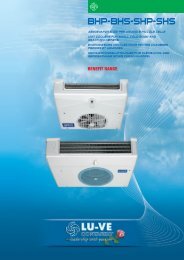
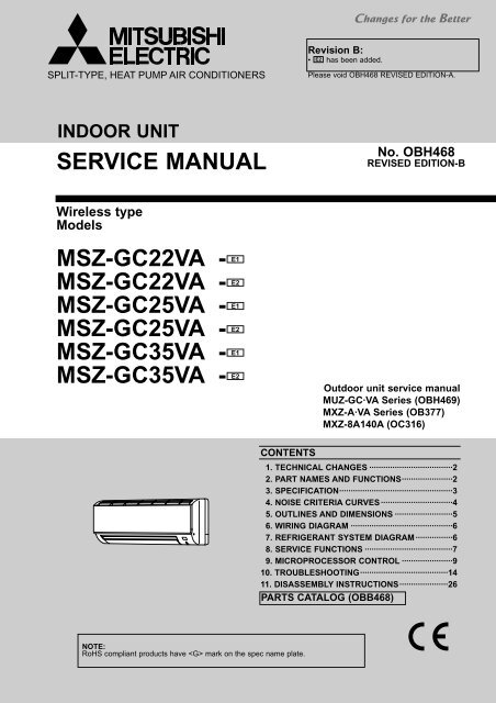
SPLIT-TYPE, HEAT PUMP AIR CONDITIONERSRevision B:• E2 has been added.Please void OBH468 REVISED EDITION-A.INDOOR UNITSERVICE MANUALWireless typeModelsE1MSZ-GC22VA -E2MSZ-GC22VA -E1MSZ-GC25VA -E2MSZ-GC25VA -E1MSZ-GC35VA -MSZ-GC35VA - E2No. OBH468REVISED EDITION-BOutdoor unit service manualMUZ-GC·VA Series (OBH469)MXZ-A·VA Series (OB377)MXZ-8A140A (OC316)CONTENTS1. TECHNICAL CHANGES ····································22. PART NAMES AND FUNCTIONS······················23. SPECIFICATION·················································34. NOISE CRITERIA CURVES ·······························45. OUTLINES AND DIMENSIONS ·························56. WIRING DIAGRAM ············································67. REFRIGERANT SYSTEM DIAGRAM ················68. SERVICE FUNCTIONS ······································79. MICROPROCESSOR CONTROL ······················910. TROUBLESHOOTING······································1411. DISASSEMBLY INSTRUCTIONS·····················26PARTS CATALOG (OBB468)NOTE:RoHS compliant products have mark on the spec name plate.
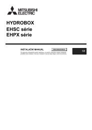
Revision A:• 10.TROUBLESHOOTING has been corrected.• Color of lead wire (indoor fan motor : sensor part) of 10-5.”Trouble criterion of main parts” has been corrected.• 10-6.”ACheck of indoor fan motor” has been corrected.Revision B:• E2 has been added.1 TECHNICAL CHANGESMSZ-GA22VA - E1 ➔ MSZ-GC22VA - E1MSZ-GA25VA - E1 ➔ MSZ-GC25VA - E1MSZ-GA35VA - ➔ MSZ-GC35VA - E11. Indoor model has been changed.MSZ-GC22VA - E1 ➔ MSZ-GC22VA - E2MSZ-GC25VA - E1 ➔ MSZ-GC25VA - E2MSZ-GC35VA - ➔ MSZ-GC35VA - E21. Panel has been changed.2PART NAMES AND FUNCTIONSMSZ-GC22VAMSZ-GC25VAMSZ-GC35VAAir cleaning filter(Anti-allergy enzyme filter, option)Air inletCatechin air filterFront panelLine flow fanAir outletVertical vaneRemote controllerHorizontal vaneRemote controlreceiving sectionEmergency operation switch (E.O. SW)Operation Indicatorlamp2
MSZ-GC22VAMSZ-GC25VAMSZ-GC35VAACCESSORIES1234567Installation plateInstallation plate fixing screw 4 o 25 mmRemote controller holderFixing screw for 3 3.5 o 1.6 mm (Black)Battery (AAA) for remote controllerWireless remote controllerFelt tape (Used for left or left-rear piping)15122113SPECIFICATIONIndoor modelMSZ-GC22VAMSZ-GC25VAMSZ-GC35VAFunctionPower supplyAir flow(Super High)CapacityAir flow(High/Med./Low)Running current ✽1Power input ✽1Fan motor current ✽1Fan motor ModelDimensions WOHODWeightAir directionSound level (Super High)Sound level (High/Med./Low)Fan speed (Super High)Fan speed (High/Med./Low)Fan speed regulatorRemote controller modelElectricaldataSpecialremarksK /hK /hAWAmmkgdB(A)dB(A)rpmrpmCooling576462/354/2461,070890/720/550Heating600480/378/2761,100920/760/60036/29/21Cooling HeatingSingle phase230V,50Hz576462/354/2460.22400.22RC4V18-BA or CA788O295O23494431,070890/720/5504KM05B600480/378/2761,100920/760/600Cooling552444/330/2341,110930/740/58036/29/22Heating570462/354/2461,140960/780/600NOTE : Test conditions are based on ISO 5151Cooling : Indoor Dry-bulb temperature 27:Wet-bulb temperature 19:Outdoor Dry-bulb temperature 35:Heating : Indoor Dry-bulb temperature 20:Outdoor Dry-bulb temperature 7:Wet-bulb temperature 6:Refrigerant piping length (one way): 5m✽1 Measured under rated operating frequency.Specifications and rating conditions of main electric partsFuseHorizontal vane motorVaristorTerminal block(F11)(MV)(NR11)(TB)T3.15AL 250V12V DCS10K320E3K1(ERZV14D471)3P3
4 NOISE CRITERIA CURVESMSZ-GC22VAMSZ-GC25VAMSZ-GC35VAFAN SPEEDFUNCTION SPL(dB(A)) LINEFAN SPEEDFUNCTION SPL(dB(A)) LINESuper HighCOOLINGHEATING4343Super HighCOOLINGHEATING43439090OCTAVE BAND SOUND PRESSURE LEVEL, dB re 0.0002 MICRO BAR8070605040302010APPROXIMATETHRESHOLD OFHEARING FORCONTINUOUSNOISE63 125 250 500 1000 2000 4000 8000NC-70NC-60NC-50NC-40NC-30NC-20OCTAVE BAND SOUND PRESSURE LEVEL, dB re 0.0002 MICRO BAR8070605040302010APPROXIMATETHRESHOLD OFHEARING FORCONTINUOUSNOISE63 125 250 500 1000 2000 4000 8000NC-70NC-60NC-50NC-40NC-30NC-20BAND CENTER FREQUENCIES, HzBAND CENTER FREQUENCIES, HzTest conditionsCooling : Dry-bulb temperature 27: Wet-bulb temperature 19:Heating : Dry-bulb temperature 20:INDOOR UNIT1mWALL0.8mMICROPHONE4
5OUTLINES AND DIMENSIONSMSZ-GC22VAMSZ-GC25VAMSZ-GC35VAUnit : mm78811 X 26 Oblong hole 11 X 20 Oblong hole59 225 22559Installation plate254.521521418.5235253.5Indoor unit40.559335Air in155 15532074241.5Wall hole [65234 5Installation platePiping829553 607 128100Air out119137Drain hose5815919PipingInsulation [35 O.DLiquid line [6.35 - 0.5 m (Flared connection [6.35)Gas line [9.52 - 0.43 m (Flared connection [9.52)Drain hose Insulation [28 O.D Connected part [16 O.D5
6 WIRING DIAGRAMMSZ-GC22VAMSZ-GC25VAMSZ-GC35VA7REFRIGERANT SYSTEM DIAGRAMMSZ-GC22VAMSZ-GC25VAMSZ-GC35VARefrigerant pipe [9.52(with heat insulator)Unit : mmIndoorheatexchangerIndoor coilthermistorRT12 (main)Flared connectionIndoor coilthermistorRT13 (sub)Room temperaturethermistorRT11Flared connectionRefrigerant pipe [6.35(with heat insulator)Refrigerant flow in coolingRefrigerant flow in heating6
8SERVICE FUNCTIONSMSZ-GC22VAMSZ-GC25VAMSZ-GC35VA8-1. TIMER SHORT MODEFor service, set time can be shortened by short circuit of JPG and JPS on the electronic control P.C. board.The time will be shortened as follows. (Refer to 10-7.)Set time : 1-minute ➔ 1-secondSet time : 3-minute ➔ 3-second (It takes 3 minutes for the compressor to start operation. However, the starting time isshortened by short circuit of JPG and JPS.)8-2. P.C. BOARD MODIFICATION FOR INDIVIDUAL OPERATIONA maximum of 4 indoor units with wireless remote controllers can be used in a room.In this case, to operate each indoor unit individually by each remote controller, P.C. boards of remote controller must bemodified according to the number of the indoor unit.How to modify the remote controller P.C. boardRemove batteries before modification.The board has a print as shown below :Table 1J1The P.C. board has the print “J1” and “J2”. Solder “J1” and “J2” according to the number of indoor unit as shown in Table 1.After modification, press the RESET button.J2NOTE : For modification, take outthe batteries and press theOPERATE/STOP(ON/OFF)button twice or 3 times atfirst.After modification, put backthe batteries then pressthe RESET button.No. 1 unitNo. 2 unitNo. 3 unitNo. 4 unit1 unit operationNo modification–––2 units operationSame as at leftSolder J1––3 units operationSame as at leftSame as at leftSolder J2–4 units operationSame as at leftSame as at leftSame as at leftSolder both J1 and J2How to set the remote controller exclusively for particular indoor unitAfter you turn the breaker ON, the first remote controller that sends the signal to the indoor unit will be regarded as the remotecontroller for the indoor unit.The indoor unit will only accept the signal from the remote controller that has been assigned to the indoor unit once they areset.The setting will be cancelled if the breaker is turned OFF, or the power supply is shut down.Please conduct the above setting once again after the power has restored.7
8-3. AUTO RESTART FUNCTIONWhen the indoor unit is controlled with the remote controller, the operation mode, the set temperature, and the fan speedare memorized by the indoor electronic control P.C. board. “AUTO RESTART FUNCTION” automatically starts operationin the same mode just before the shutoff of the main power.Operation1 If the main power has been cut, the operation settings remain.2 After the power is restored, the unit restarts automatically according to the memory.(However, it takes at least 3 minutes for the compressor to start running.)How to release “AUTO RESTART FUNCTION”1Turn off the main power for the unit.2Solder the jumper wire to JR07 on the indoor electronic control P.C. board. (Refer to 10-7.)Indoor electroniccontrol P.C. boardCN10A CN151 CN112 CN111NOTE :• The operation settings are memorized when 10 seconds have passed after the indoor unit was operated with theremote controller.• If main power is turned OFF or a power failure occurs while AUTO START/STOP timer is active, the timer setting iscancelled.• If the unit has been off with the remote controller before power failure, the auto restart function does not work as thepower button of the remote controller is off.• To prevent breaker OFF due to the rush of starting current, systematize other home appliance not to turn ON at thesame time.• When some air conditioners are connected to the same supply system, if they are operated before power failure,the starting current of all the compressors may flow simultaneously at restart.Therefore, the special counter-measures are required to prevent the main voltage-drop or the rush of the startingcurrent by adding to the system that allows the units to start one by one.JR078
9MICROPROCESSOR CONTROLMSZ-GC22VAMSZ-GC25VAMSZ-GC35VAWIRELESS REMOTE CONTROLLERSignal transmitting sectionOperation display sectionOPERATE/STOP(ON/OFF) buttonOpen the front lid.FAN SPEED CONTROL buttonOPERATION SELECT buttonECONO COOL buttonTemperature buttonsRESET buttonOFF TIMER buttonON TIMER buttonTIME SET buttonsFORWARD buttonBACKWARD buttonCLOCK SET buttonVANE CONTROL buttonIndication ofremote controllermodel is on backOnce the operation mode is set, the same operation mode can be repeated by simply turning OPERATE/STOP(ON/OFF) button ON.Indoor unit receives the signal with a beep tone.When the system turns off, 3-minute time delay will operate to protect system from overload and compressor will notrestart for 3 minutes.INDOOR UNIT DISPLAY SECTIONOperation Indicator lampThe operation indicator at the right side of the indoor unit indicates the operation state.•The following indication applies regardless of shape of the indicator.IndicationOperation stateRoom temperatureThe unit is operatingto reach the settemperatureThe room temperatureis approachingthe set temperatureAbout 2 : or moreaway fromset temperatureAbout 1 to 2 : fromset temperatureLightedBlinkingNot lightedStandby mode(only during multisystem operation)9
9-1. COOL ( ) OPERATION(1) Press OPERATE/STOP(ON/OFF) button.OPERATION INDICATOR lamp of the indoor unit turns on with a beep tone.(2) Select COOL mode with OPERATION SELECT button.(3) Press TEMPERATURE buttons (TOO WARM or TOO COOL button)to select the desired temperature.The setting range is 16 ~ 31°C.1. Coil frost preventionThe compressor operational frequency is controlled by the temperature of the indoor heat exchanger to prevent the coilfrom frosting.When the temperature of indoor heat exchanger becomes too low, the coil frost prevention mode works.The indoor fan operates at the set speed and the compressor stops. This mode continues until the temperature of indoorheat exchanger rises.2. Low outside temperature operationWhen the outside temperature is lower, low outside temperature operation starts, and the outdoor fan slows or stops.9-2. DRY ( ) OPERATION(1) Press OPERATE/STOP(ON/OFF) button.OPERATION INDICATOR lamp of the indoor unit turns on with a beep tone.(2) Select DRY mode with OPERATION SELECT button.(3) The set temperature is determined from the initial room temperature.1. Coil frost preventionCoil frost prevention is as same as COOL mode. (9-1.1.)2. Low outside temperature operationLow outside temperature operation is as same as COOL mode. (9-1.2.)9-3. HEAT ( ) OPERATION(1) Press OPERATE/STOP(ON/OFF) button.OPERATION INDICATOR lamp of the indoor unit turns on with a beep tone.(2) Select HEAT mode with OPERATION SELECT button.(3) Press TEMPERATURE buttons (TOO WARM or TOO COOL button) to select the desired temperature.The setting range is 16 ~ 31°C.1. Cold air prevention controlWhen the compressor is not operating or is starting, and the temperature of indoor heat exchanger and/or the room temperatureis low or when defrosting is being done, the indoor fan will stop or rotate in Very Low speed.2. High pressure protectionThe compressor operational frequency is controlled by the temperature of the indoor heat exchanger to prevent the condensingpressure from increasing excessively.When the temperature of indoor heat exchanger becomes too high, the high pressure protection works.The indoor fan operates following the cold air prevention control. This mode continues until the temperature of indoorheat exchanger falls.3. DefrostingDefrosting starts when the temperature of outdoor heat exchanger becomes too low.The compressor stops once, the indoor/outdoor fans stop, the 4-way valve reverses, and the compressor re-starts.This mode continues until the temperature of outdoor heat exchanger rises or the fixed time passes.9-4. AUTO CHANGE OVER ··· AUTO MODE OPERATIONOnce desired temperature is set, unit operation is switched automatically between COOL and HEAT operation.Mode selection(1) Initial modeWhen unit starts the operation with AUTO operation from off;• If the room temperature is higher than the set temperature, operation starts in COOL mode.• If the room temperature is equal to or lower than the set temperature, operation starts in HEAT mode.(2) Mode changeCOOL mode changes to HEAT mode when about 15 minutes have passed with the room temperature 2 degreesbelow the set temperature.HEAT mode changes to COOL mode when about 15 minutes have passed with the room temperature 2 degreesabove the set temperature.NOTE 1If two or more indoor units are operating in multi system, there might be a case that the indoor unit, which is operatingin (AUTO), cannot change over to the other operating mode (COOL HEAT) and becomes a state of standby.Refer to NOTE 2 “FOR MULTI SYSTEM AIR CONDITIONER”.10
NOTE 2FOR MULTI SYSTEM AIR CONDITIONEROUTDOOR UNIT : MXZ seriesMulti system air conditioner can connect two or more indoor units with one outdoor unit.•Unit won’t operate in case the total capacity of indoor units exceeds the capacity of outdoor units. Do not connectindoor units beyond the outdoor unit capacity.Operation indicator lamp flashes as shown in the figure below.•When you try to operate two or more indoor units with one outdoor unit simultaneously, one for the cooling andthe others for heating, the operation mode of the indoor unit that operates earlier is selected. The other indoorunits cannot operate, indicating as shown in the figure below. In this case, please set all the indoor units to thesame operation mode.OPERATION INDICATORLightedBlinkingNot lighted•When indoor unit starts the operation while the defrosting of outdoor unit is being done, it takes a fewminutes(max. 10 minutes) to blow out the warm air.•In the heating operation, though indoor unit that does not operate may get warm or the sound of refrigerantflowng may be heard, they are not malfunction. The reason is that the refrigerant continuously flows into it.9-5. AUTO VANE OPERATION1. Horizontal vane(1) Vane motor driveThese models are equipped with a stepping motor for the horizontal vane. The rotating direction, speed, and angle ofthe motor are controlled by pulse signals (approx. 12V) transmitted from indoor microprocessor.(2) The horizontal vane angle and mode change as follows by pressing VANE CONTROL button.(3) PositioningTo confirm the standard position, the vane moves until it touches the vane stopper. Then the vane is set to the selectedangle.Confirming of standard position is performed in the following cases:(a) When the operation starts or finishes (including timer operation).(b) When the test run starts.(c) When standby mode (only during multi system operation) starts or finishes.(4) VANE AUTO ( ) modeIn VANE AUTO mode, the microprocessor automatically determines the vane angle to make the optimum room temperaturedistribution.In COOL and DRY operationIn HEAT operationHorizontalpositionVane angle is fixed to Horizontal position.Vane angle is fixed to Angle 4.(5) STOP (operation OFF) and ON TIMER standbyIn the following cases, the horizontal vane returns to the closed position.(a) When OPERATE/STOP (ON/OFF) button is pressed (POWER OFF).(b) When the operation is stopped by the emergency operation.(c) When ON TIMER is ON standby.(6) Dew preventionDuring COOL or DRY operation with the vane angle at Angle 2 ~ 4 when the compressor cumulative operation timeexceeds 1 hour, the vane angle automatically changes to Angle 1 for dew prevention.11
(7) SWING ( ) modeBy selecting SWING mode with VANE CONTROL button, the horizontal vane swings vertically.(8) Cold air prevention in HEAT operationThe horizontal vane position is set to Upward.NOTE : When 2 or more indoor units are operated with multi outdoor unit, even if any indoor unit turns thermostatoff, this control doesn’t work in the indoor unit.(9) To change the air flow direction not to blow directly onto your body.To change the airflow directionPressing and holdingVANE CONTROLbutton for 2 secondsor more causesthe horizontal vaneto reverse andmove to horizontalposition.HorizontalpositionWhen to use this function?Use this function if you don’twant the air from the indoorunit to blow directly onto yourbody.• Depending on the shape ofthe room, the air may blowdirectly onto your body.• Press VANE CONTROLbutton again to return thevane to the previously-setposition.The air conditioner starts thecooling or drying operationapprox. 3 minutes after thevane has moved to the horizontalposition.• When VANE CONTROLbutton is pressed again,the vane returns to thepreviously-set positionand the air conditionerstarts the cool or dryoperation in approx.3 minutes.12COOL/DRYHEATThe air conditioner starts heatingoperation approx. 3 minutesafter the vane has moved to thehorizontal position.• Sometimes the areaaround your feet may notwarm. To warm the areaaround the feet, set thehorizontal vane to(AUTO) or the downwardblowingposition.• When VANE CONTROLbutton is pressed again,the vane returns to thepreviously-set positionand the air conditionerstarts the heat operationin approx. 3 minutes.NOTE :• If you make the air flow not to blow directly onto your body by pressing VANE CONTROL button,the compressor stops for 3 minutes even during the operation of the air conditioner.• The air conditioner operates with Very Low speed until the compressor turns on again.(10) ECONO COOL ( ) operation (ECONOmical operation)When ECONO COOL button is pressed in COOL mode, set temperature is automatically set 2°C higher.Also the horizontal vane swings in various cycle.SWING operation makes you feel cooler than set temperature. So, even though the set temperature is higher, the airconditioner can keep comfort. As a result, energy can be saved.ECONO COOL operation is cancelled when ECONO COOL button is pressed once again or VANE CONTROLbutton is pressed or change to other operation mode.9-6. TIMER OPERATION1. How to set the time(1) Check that the current time is set correctly.NOTE : Timer operation will not work without setting the current time. Initially “AM0:00” blinks at the current time displayof TIME MONITOR, so set the current time correctly with CLOCK SET button.How to set the current time(a) Press the CLOCK set button.(b) Press the TIME SET buttons ( and ) to set the current time.• Each time FORWARD button ( ) is pressed, the set time increases by 1minute, and each time BACKWARD button ( ) is pressed, the set time decreases by 1minute.• Pressing those buttons longer, the set time increases / decreases by 10 minutes.(c) Press the CLOCK set button.(2) Press OPERATE/STOP (ON/OFF) button to start the air conditioner.(3) Set the time of timer.ON timer settingSTART(a) Press ON TIMER button( ) during operation.(b) Set the time of the timer using TIME SET buttons ( and ) . wOFF timer settingSTOP(a) Press OFF TIMER button ( ) during operation.(b) Set the time of the timer using TIME SET buttons ( and ). ww Each time FORWARD button ( ) is pressed, the set time increases by 10 minutes; each time BACKWARD button( ) is pressed, the set time decreases by 10 minutes.
2. To release the timerTo release ON timer, press ON TIMER button (START).To release OFF timer, press OFF TIMER button(STOP).TIMER is cancelled and the display of set time disappears.PROGRAM TIMER• OFF timer and ON timer can be used in combination. The timer of the set time that is reached first will operate first.• “ ” and “ ” display shows the order of OFF timer and ON timer operation.(Example 1) The current time is 8:00 PM.The unit turns off at 11:00 PM, and on at 6:00 AM.(Example 2) The current time is 11:00 AM.The unit turns on at 5:00 PM, and off at 9:00 PM.NOTE : If the main power is turned off or a power failure occurs while ON/OFF timer is active, the timer settingis cancelled. As these models are equipped with an auto restart function, the air conditioner starts operating withtimer cancelled when power is restored.9-7. EMERGENCY/TEST OPERATIONIn case of test run operation or emergency operation, use EMERGENCY OPERATION switch on the right side of theindoor unit. Emergency operation is available when the remote controller is missing, has failed or the batteries of theremote controller run down. The unit will start and OPERATION INDICATOR lamp will light.The first 30 minutes of operation is the test run operation. This operation is for servicing. The indoor fan runs at Highspeed and the system is in continuous operation (The thermostat does not work).After 30 minutes of test run operation, the system shifts to EMERGENCY COOL / HEAT MODE with a set temperature of24°C. The fan speed shifts to Med..In the test run or emergency operation, the horizontal vane operates in VANE AUTO ( ) mode.Emergency operation continues until EMERGENCY OPERATION switch is pressed once or twice or the unit receives anysignal from the remote controller. In case of latter, normal operation will start.NOTE : Do not press EMERGENCY OPERATION switch during normal operation.Operation mode COOL HEATSet temperature 24: 24:Fan speed Medium MediumHorizontal vane Auto AutoEMERGENCY OPERATION switch (E.O. SW)The operation mode is indicated by the OperationIndicator lamp on the indoor unit as followingOperation Indicator lampEMERGENCY COOLEMERGENCY HEATLightedNot lightedSTOP13
10 TROUBLESHOOTINGMSZ-GC22VA MSZ-GC25VA MSZ-GC35VA10-1. Cautions on troubleshooting1. Before troubleshooting, check the following:1) Check the power supply voltage.2) Check the indoor/outdoor connecting wire for mis-wiring.2. Take care of the following during servicing1) Before servicing the air conditioner, be sure to turn OFF the main unit first with the remote controller, and then afterconfirming the horizontal vane is closed, turn OFF the breaker and / or disconnect the power plug.2) Be sure to turn OFF the power supply before removing the front panel, the cabinet, the top panel, and the P.C. board.3) When removing the P.C. board, hold the edge of the board with care NOT to apply stress on the components.4) When connecting or disconnecting the connectors, hold the housing of the connector. DO NOT pull the lead wires.Lead wiringHousing point3. Troubleshooting procedure1) First, check if the OPERATION INDICATOR lamp on the indoor unit is flashing on and off to indicate an abnormality.To make sure, check how many times the abnormality indication is flashing on and off before starting service work.2) Before servicing, check that the connector and terminal are connected properly.3) If the P.C. board is supposed to be defective, check the copper foil pattern for disconnection and the components forbursting and discoloration.4) When troubleshooting, refer to 10-2., 10-3. and 10-4.4. How to replace batteriesWeak batteries may cause the remote controller malfunction.In this case, replace the batteries to operate the remote controller normally.1 Remove the front lid and insert batteries.Then reattach the front lid.2 Press RESET button with tip end of ball point penor the like, and then use the remote controller.Insert the negative pole of thebatteries first. Check if the polarityof the batteries is correct.RESET buttonNOTE : 1. If RESET button is not pressed, the remote controller may not operate correctly.2. This remote controller has a circuit to automatically reset the microcomputer when batteries are replaced.This function is equipped to prevent the microcomputer from malfunctioning due to the voltage drop caused bythe battery replacement.5. How to install the horizontal vaneIf horizontal vane is not installed correctly, all of the operation indicator lamps will blink.In this case, install the horizontal vane correctly by following the procedures 1 to 2.NOTE : Before installation of the horizontal vane, turn OFF the power supply.2In procedure 2 lock thestoppers until they clickinto place.Lock114
10-2. Failure mode recall functionOutline of the functionThis air conditioner can memorize the abnormal condition which has occurred once.Even though LED indication listed on the troubleshooting check table (10-4.) disappears, the memorized failure detailscan be recalled.This mode is very useful when the unit needs to be repaired for the abnormality which doesn't recur.1. Flow chart of failure mode recall function for the indoor/outdoor unitOperational procedureThe cause of abnormality cannot be found because the abnormality doesn't recur.Setting up the failure mode recall functionTurn ON the power supply.1 While pressing both OPERATION SELECTbutton and TOO COOL button on the remote controller at the same time, pressRESET button.2 First, release RESET button.And release the other two buttons after all LCD in operation display section of theremote controller is displayed after 3 seconds.Press OPERATE/STOP(ON/OFF) button of the remote controller (the set temperatureis displayed) with the remote controller headed towards the indoor unit. W1W1. Regardless of normal or abnormal condition,a short beep is emitted once the signal isreceived.Does upper lamp of OPERATION INDICATORlamp on the indoor unit blink at the interval of 0.5seconds?Blinks: Either indoor or outdoor unit is abnormal.Beep is emitted at the same timingas the blinking of upper lamp ofOPERATION INDICATOR lamp. W2YesJudgment of indoor/outdoor abnormality (Blinks)Before blinking, does upper lamp ofOPERATION INDICATOR lamp stay ON for 3seconds?Stays ON for 3 seconds (without beep):The outdoor unit is abnormal.NoNo(OFF)YesIndoor unit is normal.But the outdoor unit might be abnormal because there are someabnormalities that can't be recalled with this way.Confirm if outdoor unit is abnormal according to the detailed outdoorunit failure mode recall function.The indoor unit is abnormal.Check the blinking pattern, and confirm the abnormal point with the indoor unitfailure mode table(10-2.2.).Make sure to check at least two consecutive blinking cycles. W2The outdoor unit is abnormal.Check the blinking pattern, and confirm the abnormal point with theoutdoor unit failure mode table (Refer to outdoor unit service manual.)Make sure to check at least two consecutive blinking cycles. W3Releasing the failure mode recall functionRelease the failure mode recall function by the following procedures.Turn OFF the power supply and turn it ON again.Press RESET button of the remote controller.Repair the defective parts.Deleting the memorized abnormal condition1After repairing the unit, recall the failure mode again according to"Setting up the failure mode recall function" mentioned above.2Press OPERATE/STOP(ON/OFF) button of the remote controller (the set temperature is displayed)with the remote controller headed towards the indoor unit.3Press EMERGENCY OPERATION switch so that the memorized abnormal condition is deleted.4Release the failure mode recall function according to "Releasing the failure mode recall function"mentioned above.NOTE: 1.Make sure to release the failure mode recall function once it's set up, otherwise the unit cannot operate properly.2.If the abnormal condition is not deleted from the memory, the last abnormal condition is kept memorized.W2. Blinking pattern when the indoor unit is abnormal:2.5-second OFFBlinking at 0.5-second interval2.5-second OFFBlinking at 0.5-second intervalONOFFBeepsRepeated cycleBeepsRepeated cycleBeepsRepeated cycleW3.Blinking pattern when the outdoor unit is abnormal:Blinking at 0.5-2.5-second OFF 3-second ON second interval2.5-second OFF3-second ONBlinking at 0.5-second intervalONOFFNo beepRepeated cycleBeepsNo beepRepeated cycleBeepsRepeated cycle15
2. Indoor unit failure mode tableUpper lamp of OPERATIONINDICATOR lampAbnormal point(Failure mode)ConditionCorrespondenceNot lighted Normal ——1-time flashevery 0.5-secondRoom temperaturethermistorThe room temperature thermistor shortor open circuit is detected every 8 secondsduring operation.Refer to the characteristics of the roomtemperature thermistor (10-7.).2-time flash2.5-second OFFIndoor coil thermistorThe indoor coil thermistor short or opencircuit is detected every 8 seconds duringoperation.Refer to the characteristics of the mainindoor coil thermistor, the sub indoor coilthermistor (10-7.).3-time flash2.5-second OFFSerial signalThe serial signal from outdoor unit isnot received for 6 minutes.Refer to 10-6.D "How to check mis-wiringand serial signal error".11-time flash2.5-second OFFIndoor fan motorThe rotational frequency feedback signal isnot sent out for 12-seconds after indoor fanmotor is opeated.Refer to 10-6.A "Check of indoor fanmotor".12-time flash2.5-second OFFIndoor control systemIt cannot properly read data in thenonvolatile memory of the indoor electroniccontrol P.C. board.Replace the indoor electronic controlP.C. board.NOTE : Blinking patterns of this mode differ from the ones of Troubleshooting check table (10-4.).16
10-3. Instruction of troubleshootingStartIndoor unitoperates.Outdoor unitdoesn'toperate.Indoor unit operates.Outdoor unit doesn'toperate normally.Indoor unitdoesn't receivethe signal fromremote controller.OPERATION INDICATORlamp on the indoor unit isflashing on and off.Outdoor unitoperates onlyin Test Runoperation.wOutdoor unitdoesn'toperateeven inTest Runoperation.wUnit doesn'toperatenormaloperation inCOOL orHEAT mode.Indoor unitoperates, whenEMERGENCYOPERATIONswitch is pressed.Indoor unitdoesn't operate,whenEMERGENCYOPERATIONswitch is pressed.If blinking of OPERATIONINDICATOR lamp cannot bechecked, it can be checked withfailure mode recall function.w"Test Run operation" means theoperation within 30 minutes afterEMERGENCY OPERATION switchis pressed.Check roomtemperaturethermistor.Refer to 10-7."Test pointdiagram andvoltage".Refer to"How to checkinverter/compressor".Refer to"Check ofR.V. coil".Refer to 10-6.B"Check ofremote controllerand indoorelectronic controlP.C. board".1. Check indoor / outdoorconnecting wire.(Check if the poweris supplied to theindoor unit.)2. Refer to 10-6.C"Check of indoorP.C. board and indoorfan motor".Refer to outdoor unit service manual.All lampsFlash on and offat 0.5-secondintervalsCause:Indoor unit• The horizontalvane is notinstalledcorrectly.Upper lampFlash on and offat 0.5-secondintervalsCause:Indoor/Outdoor unit• Mis-wiringor troubleof serial signalUpper lamp2-time flashCause:Indoor unit• Trouble ofroom temperature/indoor coilthermistorUpper lamp3-time flashCause:Indoor unit• Trouble ofindoor fanmotorUpper lamp4-time flashCause:Indoor unit• Trouble ofindoor unitcontrolsystemUpper lamp5-time flashCause:Outdoor unit• OutdoorpowersystemabnormalityUpper lamp6-time flashCause:Outdoor unit• Trouble ofthermistorin outdoorunitUpper lamp7-time flashCause:Outdoor unit• Trouble ofoutdoorcontrolsystemUpper lamp14-time flashCause:Outdoor unit• OtherabnormalityRefer to 10-6.E "Check ofinstallation ofthe horizontalvane".Refer to 10-6.D "How tocheck ofmis-wiringand serialsignal error".Check roomtemperaturethermistorand indoorcoil thermistor.Refer to 10-7."Test pointdiagram andvoltage".Refer to 10-6.A "Check ofindoor fanmotor".Replace theindoorelectroniccontrolP.C. board.Refer to"How to checkinverter/compressor".Refer to"Check ofoutdoorthermistors".Replace theinverter P.C.board orthe outdoorelectroniccontrol P.C.board.Check"Flow chart ofthe detailedoutdoor unitfailure moderecall function."17
10-4. Troubleshooting check tableBefore taking measures, make sure that the symptom reappears for accurate troubleshooting.When the indoor unit has started operation and the following detection method has detected an abnormality (the firstdetection after the power ON), the indoor electronic control P.C. board turns OFF the indoor fan motor withOPERATION INDICATOR lamp flashing.OPERATION INDICATORLightedBlinkingNot lightedNo.1AbnormalpointMis-Wiringor serialsignalOperation indicator lamp SymptomCondition CorrespondenceUpper lamp flashes.0.5-second ON0.5-second OFFThe serial signal from the outdoor unit is notreceived for 6 minutes.• Refer to 10-6.D "How to checkmis-wiring and serial signalerror".23Indoor coilthermistorRoomtemperaturethermistorIndoor fanmotorUpper lamp flashes.2-time flash2.5-second OFFUpper lamp flashes.3-time flash2.5-second OFFThe indoor coil or the room temperaturethermistor is short or open circuit.The rotational frequency feedback signal isnot emitted during the indoor fan operation.• Refer to 10-7.thecharacteristics of indoor coilthermistor, and the roomtemperature thermistor.• Refer to 10-6.A "Check ofindoor fan motor".456IndoorcontrolsystemOutdoorpowersystemUpper lamp flashes.4-time flashUpper lamp flashes.5-time flash2.5-second OFF2.5-second OFFUpper lamp flashes.6-time flashOutdoorthermistors2.5-second OFFIndoor unitand outdoorunit do notoperate.It cannot properly read data in the nonvolatilememory of the indoor electronic control P.C.board.It consecutively occurs 3 times that thecompressor stops for overcurrent protection orstart-up failure protection within 1 minute afterstart-up.The outdoor thermistors short or open circuitduring the compressor operation.• Replace the indoor electroniccontrol P.C. board.• Refer to "How to check ofinverter/compressor".Refer to outdoor unit servicemanual.• Check the stop valve.• Refer to "Check of outdoorthermistor".Refer to outdoor unit servicemanual.7OutdoorcontrolsystemUpper lamp flashes.7-time flash2.5-second OFFIt cannot properly read data in the nonvolatilememory of the inverter P.C. board or theoutdoor electronic control P.C. board.• Replace the inverter P.C.board or the outdoorelectronic control P.C. board.Refer to outdoor unit servicemanual.8OtherabnormalityUpper lamp flashes.14-time flash2.5-second OFFAn abnormality other than above mentioned isdetected.• Check the stop valve.• Confirm the abnormality indetail using the failure moderecall function for outdoorunit.9OutdoorcontrolsystemUpper lamp lights upOutdoor unitdoes notoperate.It cannot properly read data in the nonvolatilememory of the inverter P.C. board or theoutdoor electronic control P.C. board.• Check the blinking pattern ofthe LED on the inverter P.C.board or the outdoorelectroniccontrol P.C. board.18
OPERATION INDICATORNo.1AbnormalpointAttachmentof thehorizontalvaneOperation indicator lamp SymptomCondition CorrespondenceAll lamps flash at the same time.0.5-second ON0.5-second OFFIndoor unitand outdoorunit do notoperate.The electricity is not conducted to the interlockswitch (Fan) of the horizontal vane.• Refer to 10-6.E "Check ofinstallation of the horizontalvane".OPERATION INDICATORNo.1AbnormalpointMXZ typeOperationmodesettingOperation indicator lamp SymptomCondition CorrespondenceUpper lamp lights and lower lamp flashes.2.5-second OFFOutdoor unitoperates butindoor unitdoes notoperate.The operation mode of the each indoorunit is differently set to COOL(includes DRY)and HEAT at the same time, the operationmode of the indoor unit that has operated atfirst has the priority.• Unify the operation mode.Refer to outdoor unit servicemanual.10-5. Trouble criterion of main partsMSZ-GC22VA MSZ-GC25VA MSZ-GC35VAPart nameRoom temperaturethermistor (RT11)Indoor coil thermistor(RT12, RT13)Measure the resistance with a tester.Check method and criterionRefer to 10-7."Test point diagram and voltage","2.Indoor electronic control P.C. board", the chart of thermistor.FigureIndoor fan motor (MF)INNER FUSEBA : 135i3: CUT OFFCA : 140i2: CUT OFFMotor partSensor partMeasure the resistance between the terminals with a tester.(Part temperature 10˚C ~ 30˚C)Color of lead wireWHT – BLKBLK – REDMeasure the voltage power ON.Color of lead wireBRN – YLWBRN – GRYRC4V18-BA273 " ~ 296 "295 " ~ 320 "NormalRC4V18-CA308 " ~ 334 "295 " ~ 320 "Normal4.5 ~ 5.5V(When fan revolved one time)0V➔5V➔0V(Approx.)FUSEBLKMAINAUX.BRNYLWGRYREDWHTVane motor (MV)Measure the resistance between the terminals with a tester.(Part temperature 10°C ~ 30°C)Color of the lead wire NormalRED-BLK 235 " ~ 255 "BLKBLKREDBLKROTORBLK19
10-6. Troubleshooting flowWhen OPERATION INDICATOR lamp flashes 3-time. Indoor fan does not operate.A Check of indoor fan motorTurn OFF the power supply.Check connector CN211 visually.Reconnect the lead wires.NoAre lead wires connected?YesAre soldered points of theconnector correctly soldered toindoor power P.C. board?NoResolder it.Disconnect the lead wires from connector CN211 on indoor power P.C. board.Measure the resistance between lead wires No.1 and No.4 and then No.4 and No.7.YesIs the resistance 0 (short circuit) or ∞ (open circuit)?Yes ( 0 or ∞ )No(others)Turn ON the power supply. Rotate indoor fan slowly for 1 revolutionor over with a screwdriver etc. from air outlet, and measurethe voltage No.2(+) and No.1(-) on CN121.Replace the indoor fan motor.NoDoes the voltage repeat 0V DC and 5V DC?Indoor terminalP.C.boardIndoor power P.C.boardYesReplace the indoor power / terminal P.C. boardand the indoor electronic control P.C. board.Fuse (F11)Varistor(NR11)CN121CN211Indoor unit operates by pressing EMERGENCY OPERATION switch, but does not operate with the remote controller.B Check of remote controller and indoor electronic control P.C. boardwCheck if the remote controller is exclusive for this air conditioner.Press OPERATE/STOP(ON/OFF) button on the remote controller.Is LCD display on the the remotecontroller visible?YesNo(not clear)Replace the batteries. (Refer to 10-1.4.)Remove the batteries, then set them backand press RESET button. (Refer to 10-1.4.) Check if the unit operates with theremote controller.Does the unit operate with theremote controller?YesNoTurn ON a radio to AM and pressOPERATE/STOP(ON/OFF) button on the remote controller.OKIs noise heard from radio?NoReplace the remote controller.YesAre there any fluorescent lights ofinverter or rapid-start type withinthe range of 1m?Yes● Reinstall the unit away from lights.● Attach a filter on receiving part.NoReplace the indoor electroniccontrol P.C. board.(including the receiver)20
The unit does not operate with the remote controller.Also, OPERATION INDICATOR lamp does not light up by pressing EMERGENCY OPERATION switch.C Check of indoor P.C. board and indoor fan motorTurn OFF the power supply.Remove indoor fan motor connector CN211 from indoorpower P.C. board and vane motor connector CN151from the indoor electronic control P.C. board and turnON the power supply.Measure the resistanceRefer to 10-5 of indoor fan motor.Short circuit:Replace the indoor fan motor.YesDoes the unit operate with the remote controller?Does OPERATION INDICATOR lamp light up bypressing EMERGENCY OPERATION switch?NoMeasure the resistance of the vane motor coil.Refer to 10-5.Short circuit:Replace the vane motor and the indoorelectronic control P.C. board.Replace the varistor(NR11) and fuse(F11). wYesTurn OFF the power supply.Check both “parts side” and “patternside” of the indoor terminal P.C.board visually.Are the varistor (NR11) burntand the fuse (F11) blown?Be sure to check both the fuseand the varistor in any case.Is the fuse (F11) blown only?NoNoYesMeasure the resistance ofindoor fan motor.Refer to 10-5.Is the resistance normal?NoReplace the fuse (F11) and the indoor fan motor. wYesReplace the fuse (F11). ww. Please replace the fuse after removingthe indoor terminal P.C. board from the electrical box.Measure the resistance of cementresistor R111 on the indoor powerP.C. board.Is the resistanceapprox. 4'?NoReplace the indoor power / terminal P.C. boardand the indoor fan motor.YesIndoor electroniccontrol P.C.boardJPG (GND)Is the approx. 5VDC between 5V (+)and JPG(GND) (–) of the indoorelectronic control P.C.board? Is thereapprox. 9V to 13VDC between 12V (+)and JPG (GND) (–) of the indoorelectronic control P.C. board.YesReplace the indoor fan motor.CN10ANoIndoor terminalP.C.boardIndoor power P.C.board12VDC5VDCAre connector CN10A onthe indoor electronic controlP.C. board or lead wiresdisconnected?NoYesConnect the connector or repairdisconnection.R111Fuse (F11)Replace the indoor power / terminal P.C. board.Varistor(NR11)CN21121
• When unit cannot operate neither by the remote controller nor by EMERGENCY OPERATION switch.Indoor unit does not operate.• When OPERATION INDICATOR lamp flashes ON and OFF every 0.5-seconds.Outdoor unit does not operate.DHow to check mis-wiring and serial signal errorTurn OFF the power supply.Is there rated voltage inthe power supply?NoCheck the powersupply.YesTurn ON the power supply.Is there rated voltage betweenoutdoor terminal block S1 andS2?NoCheck the wiring.YesPress EMERGENCY OPERATION switch once.Does the upper lamp of OPERATIONINDICATOR lamp light up?NoYesIs serial signal error indicated 6 minutes later?YesNoIs there any mis-wiring,poor contact, or wiredisconnection of theindoor/outdoorconnecting wire?NoYesCorrect them.AA· Turn OFF inverter-controlled lightingequipment.· Turn OFF the power supply and thenturn ON again.· Press EMERGENCY OPERATIONswitch.Is serial signalerror indicated6 minutes later?BYesNo· Reinstalleither theunit or thelight eachother away.· Attach a filteron remotecontrolreceivingsection ofthe indoorunit.BTurn OFF the power supply.Check once more if the indoor/outdoorconnecting wire is not mis-wiring.Short-circuit outdoor terminal block S2 andS3.W1Turn ON the power supply.Does the LED on the inverter P.C. boardor the outdoor electronic control P.C. boardrepeat "3.6-second-OFF and 0.8-second-ONquick blinking"? W3YesTurn OFF the power supply.Remove the short-circuit betweenoutdoor terminal block S2 and S3.Turn ON the power supply.Is there amplitude of 10 to 20V DCbetween indoor terminal block S2and S3? Is there rated voltage betweenindoor terminal block S1 and S2?YesNoIs there 2V DC or less between CN10A3(+)and JPG(GND)(–) on the indoor electroniccontrol P.C. board?YesNoIs there 2V DC or less betweenCN10A4(+) and JPG(GND)(–)on the indoor electronic controlP.C. board?No YesReplace the indoor power /terminal P.C. board.W1. Mis-wiring may damage indoor P.C. board during theoperation.Be sure to confirm the wiring is correct before theoperation starts.W3. Be sure to check this within 3 minutes after turning ON.After 3 minutes, LED blinks 6 times. Even whenthe inverter P.C.board or the outdoor electronic controlP.C.board is normal, LED blinks 6 times after 3 minutes.(Except for outdoor unit of multi system type)No(Lighted ornot lighted)Replace the inverter P.C. board orthe outdoor electronic control P.C.board.W2W2 Be careful to the residualvoltage of smoothing capacitor.Is there any error of theindoor/outdoor connecting wire,such as the damage of the wire,intermediate connection, poorcontact to the terminal block?Be sure to release the failure-mode recall function after checking.NoReplace the indoorelectronic control P.C. board.YesIs there 2V DC or less betweenCN10A4(+) and JPG(GND)(–)on the indoor electronic controlP.C. board?NoReplace theindoor/outdoorconnecting wire.Yes22
When All lamps flash ON and OFF every 0.5-second.Indoor unit and outdoor unit do not operate.ECheck of installation of the horizontal vaneTurn OFF thepower supply.Is the stopper of the horizontal vanelocked to the indoor unit correctly?YesNoRelock the stopper of thehorizontal vane to the indoor unit.(Refer to 10-1.5.)Turn ON thepower supply.Are all lamps flashing?YesNoOKTo check the continuity of the interlock switch(Fan), measure the resistance of connector 1 - 2connected to CN1R1 on the indoorelectronic control P.C. board.Turn OFF thepower supply.Is there resistance 0 "?YesNo(∞)Replace theinterlock switch(Fan).Replace theindoor electroniccontrol P.C. board.23
FElectromagnetic noise enters into TV sets or radiosIs the unit earthed?NoEarth the unit.YesIs the distance between theantennas and the indoorunit within 3m, or is thedistance between theantennas and the outdoorunit within 3m?YesExtend the distance betweenthe antennas and the indoorunit, and/or the antennas andthe outdoor unit.NoIs the distance between theTV sets or radios and theindoor unit within 1m, or isthe distance between the TVsets or radios and theoutdoor unit within 3m?YesExtend the distance betweenthe TV sets and/or radios andthe indoor unit, or the TV setsor radios and the outdoor unit.NoAre the antennas damaged?Is the coaxial cable damaged?Is there any poor contact inthe antenna wiring?YesReplace or repair the antenna.Replace or repair the coaxial cable.NoIs the indoor/outdoorconnecting wire of the airconditioner and the wiring ofthe antennas close?YesExtend the distance betweenthe indoor/outdoor connectingwire of the air conditioner andthe wiring of the antennas.NoEven if all of the above conditions are fulfilled, the electromagnetic noise may enter, depending onthe electric field strength or the installation condition (combination of specific conditions such asantennas or wiring).Check the followings before asking for service.1.Devices affected by the electromagnetic noiseTV sets, radios (FM/AM broadcast, shortwave)2.Channel, frequency, broadcast station affected by the electromagnetic noise3.Channel, frequency, broadcast station unaffected by the electromagnetic noise4.Layout of ;indoor/outdoor unit of the air conditioner, indoor/outdoor wiring, grounding wire, antennas, wiringfrom antennas, receiver5.Electric field intensity of the broadcast station affected by the electromagnetic noise6.Presence or absence of amplifier such as booster7.Operation condition of air conditioner when the electromagnetic noise enters in.1)Turn OFF the power supply once, and then turn ON the power supply. In this situation, check forthe electromagnetic noise.2)Within 3 minutes after turning ON the power supply, press OPERATE/STOP (ON/OFF) buttonon the remote controller for power ON, and check for the electromagnetic noise.3)After a short time (3 minutes later after turning ON), the outdoor unit starts running. Duringoperation, check for the electromagnetic noise.4)Press OPERATE/STOP (ON/OFF) button on the remote controller for power OFF, when theoutdoor unit stops but the indoor/outdoor communication still runs on. In this situation, check forthe electromagnetic noise.After checking the above, consult the service representative.24
10-7. Test point diagram and voltageMSZ-GC22VA MSZ-GC25VA MSZ-GC35VA1. Indoor power P.C. board, Indoor terminal P.C. boardIndoor terminal P.C. boardIndoor power P.C. boardFuse (F11)(w)Varistor (NR11)R111Terminalblock}Indoor fan motor(CN211)230V ACConnector to indoor electroniccontrol P.C. board (CN20A)5VDC 12VDC CN121 GNDw Please replace the fuse after removing the indoor terminal P.C. board from the electrical box.2. Indoor electronic control P.C. boardTimer short modepoint JPG JPS(Refer to 8-1.)Room temperature thermistor RT11 (CN111)Indoor coil thermistor RT12, RT13(CN112)GNDInterlock switch (FAN)(CN1R1)Vane motor (CN151)Room temperature thermistor (RT11)Indoor coil thermistor (RT12, RT13)Connector toIndoor power P.C. board(CN10A)12V DCResistance (k")Emergency operationswitch (E.O.SW) (SW1)5V DCRelease of Auto restart functionSolder the Jumper wire to JR07(Refer to 8-3.)Temperature (:)25
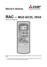
11 DISASSEMBLY INSTRUCTIONSThe terminal which has the locking mechanism can be detached as shown below.There are two types ( Refer to (1) and (2)) of the terminal with locking mechanism.The terminal without locking mechanism can be detached by pulling it out.Check the shape of the terminal before detaching.(1) Slide the sleeve and check if there is a locking lever or not. (2) The terminal with this connector has thelocking mechanism.SleeveLocking lever1Slide the sleeve.2Pull the terminal whilepushing the lockinglever.Connector1Hold the sleeve, andpull out the terminalslowly.MSZ-GC22VA MSZ-GC25VA MSZ-GC35VAOPERATING PROCEDURE1. Removing the panel(1) Remove the screw caps of the panel. Remove the screws.(2) Hold the lower ends part of the panel and pull it slightlytoward you, and then remove the panel by pushing itupward.Photo 1PHOTOSScrews of the panel26
OPERATING PROCEDURE2. Removing the indoor electronic control P.C. boardand the room temperature thermistor(1) Turn the breaker OFF.(2) Remove the panel (Refer to 1) and the corner box.(3) Open the indoor electronic control P.C. board holder (toright side), and disconnect connectors of the indoor coilthermistor (CN112), vane motor (CN151), interlock switch(CN1R1) and connector (CN10A) to the indoor power P.C.board on the indoor electronic control P.C. board.(4) Unhook the catches of the indoor electronic control P.C.board holder from the nozzle and the electrical box (rightside).(5) Remove the room temperature thermistor from the hook ofthe indoor electronic control P.C. board holder.(6) Open the back side of the indoor electronic control P.C.board holder, and remove the indoor electronic control P.C.board.(7) Remove the room temperature thermistor from the indoorelectronic control P.C. board.Photo 2PHOTOSCatch of indoor electroniccontrol P.C. board holderPhoto 3Electrical boxScrew of theelectrical coverV.A. clampIndoor electronic controlP.C. board holder3. Remove the indoor power P.C. board, the indoor terminalP.C. board, and the electrical box(1) Turn the breaker OFF.(2) Remove the panel (Refer to 1) and the corner box.(3) Remove the screw of V.A. clamp, and then the indoor/outdoorconnecting wire.(4) Remove the earth wire connected to the indoor heatexchanger from the electrical box.(5) Unhook first the lower, then the upper catches of the electricalbox, and pull out the electrical box.(6) Remove the screw of the electrical cover and remove theelectrical cover.(7) Disconnect all the connectors on the indoor power P.C.board and unhook all lead wires.(8) Remove the screw of terminal block on the indoor terminalP.C. board.(9) Remove the indoor power P.C. board and the indoor terminalP.C. board.Catch of indoor electroniccontrol P.C. board holderLower catchTerminal blockUpper catchIndoor terminalP.C. boardIndoor powerP.C. board27
OPERATING PROCEDURE4. Removing the vane motor(1) Turn the breaker OFF.(2) Remove the panel (Refer to 1) and the corner box.(3) Remove the indoor electronic control P.C. boardholder(Refer to 2).(4) Remove the screws of vane motor and remove the vanemotor.(5) Disconnect the connector from vane motor.Photo 4PHOTOSScrews of the vane motor5. Removing the indoor fan motor, the indoor coil thermistor,and the line flow fanPhoto 5(1) Remove the panel (Refer to 1) and the corner box.(2) Remove the indoor electronic control P.C. board holder (Refer to2) and the electrical box (Refer to 3) .(3) Remove the drain hose from the nozzle assembly, andremove the nozzle assembly.(4) Loosen the screw fixing the line flow fan.(5) Remove the screws fixing the motor bed. Lift the right sideof motor bed a little, and pull right to remove the fan motortogether with motor band/bed.(6) Remove the indoor coil thermistor from the heat exchanger(w) Install the indoor coil thermistor in its former position whenassembling it.(Refer to Photo 7)(7) Remove the screws fixing the left side of the heat exchanger.(8) Lift the left side of the heat exchanger, and pull out the lineflow fan to the lower-left. Photo 6Screws of the line flow fanPhoto 7Indoor coilthermistor(main)RT12Indoor coilthermistor(sub)RT13Screws of the motor bedHEAD OFFICE: TOKYO BLDG., 2-7-3, MARUNOUCHI, CHIYODA-KU, TOKYO 100-8310, JAPANC Copyright 2006 MITSUBISHI ELECTRIC ENGINEERING CO.,LTDDistributed in Aug. 2007. No. OBH468 REVISED EDITION-B 6Distributed in Feb. 2007. No. OBH468 REVISED EDITION-A 6Distributed in Dec. 2006. No. OBH468 6Made in JapanNew publication, effective Aug. 2007Specifications subject to change without notice.