msz-gc35va
msz-gc35va
msz-gc35va

Create successful ePaper yourself
Turn your PDF publications into a flip-book with our unique Google optimized e-Paper software.
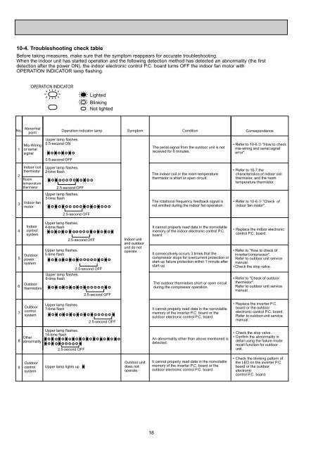
10-4. Troubleshooting check tableBefore taking measures, make sure that the symptom reappears for accurate troubleshooting.When the indoor unit has started operation and the following detection method has detected an abnormality (the firstdetection after the power ON), the indoor electronic control P.C. board turns OFF the indoor fan motor withOPERATION INDICATOR lamp flashing.OPERATION INDICATORLightedBlinkingNot lightedNo.1AbnormalpointMis-Wiringor serialsignalOperation indicator lamp SymptomCondition CorrespondenceUpper lamp flashes.0.5-second ON0.5-second OFFThe serial signal from the outdoor unit is notreceived for 6 minutes.• Refer to 10-6.D "How to checkmis-wiring and serial signalerror".23Indoor coilthermistorRoomtemperaturethermistorIndoor fanmotorUpper lamp flashes.2-time flash2.5-second OFFUpper lamp flashes.3-time flash2.5-second OFFThe indoor coil or the room temperaturethermistor is short or open circuit.The rotational frequency feedback signal isnot emitted during the indoor fan operation.• Refer to 10-7.thecharacteristics of indoor coilthermistor, and the roomtemperature thermistor.• Refer to 10-6.A "Check ofindoor fan motor".456IndoorcontrolsystemOutdoorpowersystemUpper lamp flashes.4-time flashUpper lamp flashes.5-time flash2.5-second OFF2.5-second OFFUpper lamp flashes.6-time flashOutdoorthermistors2.5-second OFFIndoor unitand outdoorunit do notoperate.It cannot properly read data in the nonvolatilememory of the indoor electronic control P.C.board.It consecutively occurs 3 times that thecompressor stops for overcurrent protection orstart-up failure protection within 1 minute afterstart-up.The outdoor thermistors short or open circuitduring the compressor operation.• Replace the indoor electroniccontrol P.C. board.• Refer to "How to check ofinverter/compressor".Refer to outdoor unit servicemanual.• Check the stop valve.• Refer to "Check of outdoorthermistor".Refer to outdoor unit servicemanual.7OutdoorcontrolsystemUpper lamp flashes.7-time flash2.5-second OFFIt cannot properly read data in the nonvolatilememory of the inverter P.C. board or theoutdoor electronic control P.C. board.• Replace the inverter P.C.board or the outdoorelectronic control P.C. board.Refer to outdoor unit servicemanual.8OtherabnormalityUpper lamp flashes.14-time flash2.5-second OFFAn abnormality other than above mentioned isdetected.• Check the stop valve.• Confirm the abnormality indetail using the failure moderecall function for outdoorunit.9OutdoorcontrolsystemUpper lamp lights upOutdoor unitdoes notoperate.It cannot properly read data in the nonvolatilememory of the inverter P.C. board or theoutdoor electronic control P.C. board.• Check the blinking pattern ofthe LED on the inverter P.C.board or the outdoorelectroniccontrol P.C. board.18