
Create successful ePaper yourself
Turn your PDF publications into a flip-book with our unique Google optimized e-Paper software.
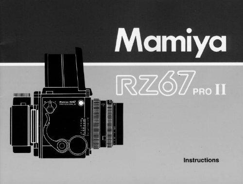
Congratulations on your purchase<br />
of a <strong>Mamiya</strong> <strong>RZ67</strong> <strong>PRO</strong> <strong>II</strong><br />
The <strong>Mamiya</strong> <strong>RZ67</strong> <strong>PRO</strong> <strong>II</strong> is the latest and most advanced model<br />
of <strong>Mamiya</strong>'s famous 6 x 7 cm SLR camera series, distinguished by<br />
their Revolving Back and rack and pinion Bellows Focusing.<br />
The result of <strong>Mamiya</strong>'s long experience and accomplishments in<br />
the professional medium format camera field, it combines<br />
mechanical perfection with the latest opto-electronic technology.<br />
Complimented by its large selection of world-class <strong>Mamiya</strong> lenses<br />
and many other system accessories, the <strong>RZ67</strong> has become the<br />
camera of choice of the world's top photographers.<br />
The <strong>RZ67</strong> <strong>PRO</strong> <strong>II</strong> is a versatile camera, ideally suited for many<br />
photographic applications, including commercial, portrait, fashion,<br />
industrial, nature and scientific photography.<br />
In order to take full advantage of its capabilities and to insure<br />
proper operation, please read this instruction manual carefully<br />
before you use your new camera.
Contents<br />
Special Features of the <strong>Mamiya</strong> <strong>RZ67</strong> <strong>PRO</strong> <strong>II</strong> ..............2 The Revolving Back ............................................................. 29<br />
Nomenclature and Functions ...........................................4 Distance Scale • Depth-of-Field ........................................ 30<br />
<strong>Mamiya</strong> <strong>RZ67</strong> <strong>PRO</strong> <strong>II</strong> Specifications ............................ 10 Long Exposures ................................................................... 31<br />
Inserting the Battery ........................................................ 11 Multiple Exposures • Infrared Photography ..................... 32<br />
Attaching / Removing Lenses ........................................ 12 Mirror Lock-up Operation .................................................... 33<br />
Using the Waist-Level Finder ......................................... 14 Flash Photography • Using a Tripod ................................. 34<br />
Interchanging the Focusing Screen .............................. 16 Close-up Photography ........................................................ 35<br />
Releasing the Shutter .................................................... 17 Attaching a Lens with<br />
Shutter Speed and Aperture .......................................... 21 Shutter Released or Mirror Raised ................................... 36<br />
The Roll Film Holder ........................................................ 22 Camera Back Lock System ................................................ 37<br />
Loading the Film Holder .................................................. 24 How to Use the Carrying Strap .......................................... 38<br />
Taking Photographs ........................................................ 27 Troubleshooting ................................................................... 39<br />
Unloading Exposed Film ................................................. 27 Using RB Series Lenses and Accessories ...................... 40<br />
Focusing and Locking the Focusing Knob ................... 28 Care of the Camera ............................................................. 41<br />
1
Special Features of the <strong>Mamiya</strong> <strong>RZ67</strong> <strong>PRO</strong> <strong>II</strong><br />
1. The Ideal Format<br />
The 6x7 cm format is called the ideal format because it<br />
enlarges to the standard 8x10" paper size without cropping,<br />
thus utilizing the entire image area. The 6x7 format of the RZ<br />
<strong>PRO</strong> <strong>II</strong> (actual image size is 56x69.5mm) is almost 5x larger<br />
than a 35mm frame and offers far superior image quality for<br />
enlargement or full page magazine reproduction. 6x7<br />
transparencies can be viewed on the light table without<br />
magnifiers.<br />
2. <strong>Mamiya</strong> Revolving Back with Automatic<br />
Finder Masking<br />
With a flip of the wrist, the Revolving Back-a <strong>Mamiya</strong><br />
exclusive among 6x7 SLRs-can be rotated for horizontal or<br />
vertical format without changing the optical axis. At the same<br />
time it also automatically changes the masking frame in the<br />
finder to match the format. Other cameras require removing<br />
and reattaching film holders when changing format or having<br />
to turn the camera on its side which complicates viewing and<br />
operation.<br />
2<br />
3. Rack and Pinion Bellows Focusing<br />
Bellows focusing, another great advantage, permits precise<br />
focusing with the left or right hand and also features a focus<br />
lock lever. The RZ <strong>PRO</strong> <strong>II</strong> has an additional micro focus knob<br />
for precise fine focusing. The camera bellows eliminate the<br />
extra costs of equipping each lens with a helical focusing<br />
mount and permits close-up photography without costly<br />
attachments. (The closest focusing distance of the 110mm lens<br />
is 31.3cm, the 65mm wide angle lens 8.5cm and the 180mm is<br />
84.5cm).<br />
4. World-Class <strong>Mamiya</strong> Lenses<br />
<strong>Mamiya</strong> world-class lens quality is a major reason for the top<br />
reputation of <strong>Mamiya</strong> camera. <strong>Mamiya</strong> operates its own<br />
modern optical design, engineering and manufacturing plant<br />
and accepts undivided responsibility for the perfect<br />
performance of its cameras and lenses. The <strong>RZ67</strong> <strong>PRO</strong> <strong>II</strong><br />
camera features a large diameter 61mm lens mount which<br />
makes it possible to design a variety of high performance<br />
lenses, such as APO, Shift and Zoom.
5. Bright, Interchangeable Finders and<br />
Focusing Screens<br />
A Waist Level Finder FW702 with self-erecting focusing hood<br />
and magnifier is factory supplied with each camera.<br />
The eye-level AE Prism Finder FE701 is an important<br />
accessory. It features three-way metering (average, spot or<br />
auto shift) and computerized, aperture-priority shutter control,<br />
compatible with the intermediate shutter speeds. It can also<br />
be operated manually. Exposure compensation to +/- 3EV and<br />
AE Lock are other features. All RB67 finders can also be<br />
used.<br />
6. Interchangeable Film Holders with Maximum<br />
Film Flatness.<br />
Available for 120 or 220 films and made in 6x7, 6x6 and<br />
6x4.5 formats. Also Polaroid holder. The film holders can be<br />
quickly interchanged, even in mid-roll. Two film counter<br />
windows permit easy reading as film holders are rotated on<br />
cameras' revolving back.<br />
Dark slide storage drawer is another feature.<br />
7. Electronic Interface<br />
The ISO film speed dial is located on the film holders and<br />
3<br />
interfaces electronically, through gold plated contacts, with<br />
the camera body, AE Prism Finder FE701 and RZ lenses.<br />
You set the dial when you load the film and never have to<br />
worry about correct meter indexing.<br />
8. Mirror Lock-up operation<br />
Locking the mirror in the up position eliminates all<br />
possible vibrations and is especially important in close-up<br />
and telephoto work, when slow shutter speeds are required.<br />
9. Multiple Exposures<br />
Multiple exposures are easy with a flip of a switch. No<br />
removal of film holder is required.<br />
10. New Features<br />
• Modern, functional design<br />
• Rugged interior mechanisms<br />
• Intermediate shutter speeds<br />
• Micro focusing knob.<br />
• Roll Film Holders with dual exposure counters<br />
• "RBL" shutter speed dial setting when using RB67 lenses.
Nomenclature and Functions<br />
Body<br />
R-M Lever<br />
For normal operation, lever is<br />
aligned with center index mark.<br />
"M": For making Multiple Exposures<br />
set it to "M". This will disengage<br />
the film transport when<br />
cocking the shutter. Do not forget<br />
to return it to center position<br />
afterwards. This setting is<br />
also used to exercise the camera<br />
without film.<br />
"R": Turning the lever to "R" unlocks<br />
and permits rotating the<br />
Revolving Back.<br />
Cocking Lever<br />
In a single operation this lever advances<br />
the film, cocks the shutter,<br />
and sets the mirror. For proper<br />
operation, be sure to push the<br />
lever completely down.<br />
Distance Scale<br />
A single scale indicating distance<br />
in meters and feet is used for all<br />
lenses.<br />
Focal Length Scale<br />
Curved lines representing most focal<br />
lengths appear on this scale.<br />
The point at which the appropriate<br />
focal length curve intersects the<br />
Distance Graduation indicates the<br />
distance focused upon by the lens.<br />
Dual Focusing Knob<br />
For regular and fine focusing.<br />
Focusing Screen<br />
The visible field of the focusing<br />
screen automatically changes<br />
from vertical to horizontal format,<br />
or vice-versa, as the revolving<br />
back is rotated. The screen it self<br />
is also interchangeable.<br />
Release Button Collar<br />
For normal operation the white dot (❑) on the Release Button<br />
Collar is kept aligned with the white dot on the Collar<br />
Stop Lever. Aligning the white dot of the collar with the red<br />
dot on the camera body locks the Shutter Release Button.<br />
Aligning the collar with the orange dot makes it possible to<br />
operate the shutter at approximately 1/400 sec. without<br />
batteries in the camera.<br />
4<br />
Gold Plated Contacts<br />
Interface AE Prism Finder electronically<br />
with camera, lens and<br />
film holder.<br />
When using an RB67 PD Prism<br />
Finder or PD Magnifying Finder<br />
on the RZ <strong>PRO</strong><strong>II</strong>, be sure to first<br />
attach the small plastic cover,<br />
which comes packed with the RZ<br />
<strong>PRO</strong><strong>II</strong>, over the contacts. (See<br />
instructions packed with cover).<br />
Lens Alignment Dot<br />
Mirror<br />
Do not touch the mirror under any<br />
circumstances.<br />
Auxiliary Electronic Shutter<br />
Release Contacts<br />
Sliding the cover upwards reveals<br />
its contacts.<br />
Shutter Release Button<br />
Collar Stop Lever<br />
This safety feature prevents the<br />
Release Button Collar from<br />
being rotated to the orange dot<br />
until the Collar Stop Lever is first<br />
depressed.
Shutter Speed Dial<br />
Speeds from 8 to 1/400 sec.<br />
Between 4 and 1/250 sec. there<br />
are intermediate settings with click<br />
stops. When set to "AEL" or "RBL"<br />
dial is locked. To release press<br />
center button. (See page 21)<br />
Carrying Strap Lug<br />
Lock Release Button<br />
Hot-Shoe<br />
Focusing Knob Lock Lever<br />
Winder Coupler Cover<br />
Tripod Socket<br />
The socket has standard U 1/4"<br />
threads which can be removed<br />
and converted to a 3/8" socket.<br />
Alignment Mark<br />
Revolving Ring<br />
Its small orange circle clicks into<br />
place and must always be<br />
aligned with the orange index<br />
marks in the 12 o'clock or 3<br />
o'clock positions.<br />
Film Advance Coupler<br />
The central pin transmits a signal<br />
to the film holder which disengages<br />
the film advance-stop and<br />
activates the multiple exposure<br />
prevention mechanism.<br />
Light Baffle<br />
To avoid damaging the baffle<br />
and camera, do not touch.<br />
Film Holder Mount Pin<br />
One of four.<br />
Battery Chamber Cover<br />
The camera use a 6 V alkaline or<br />
silver oxide battery.<br />
Contacts for Power Winder
Waist-Level Finder<br />
Magnifier Release<br />
To raise the magnifier, push the<br />
Magnifier Release to the left.<br />
Magnifier<br />
Interchangeable with other magnifiers<br />
in various diopter strengths.<br />
Finder Release Button<br />
To remove the finder, Push in on<br />
both (right and left) release<br />
buttons and lift the finder off<br />
camera body.<br />
Finder Catch<br />
6<br />
Roll Film Holder<br />
Alignment Mark<br />
Dark Slide Release Pin<br />
Holder Lock Pin<br />
The upper and lower holder lock<br />
pins prevent the holder from<br />
coming off position when<br />
mounted on the camera body.<br />
Film Advance Knob<br />
Dual Exposure Counter<br />
Features vertical and horizontal<br />
windows.<br />
Memo Clip<br />
Holds the film box top as a filmtype<br />
reminder or a memo.<br />
Dark Slide Storage Slot
Spool Release Pins<br />
Depress these pins to insert or<br />
remove film.<br />
Film Spool Stud<br />
A new roll of film is loaded on<br />
this stud with the paper leader<br />
pulled over the roller in the<br />
direction indicated by the dotted<br />
line and arrow which appears<br />
around the stud.<br />
Start Mark<br />
The start mark on the backing<br />
paper must be aligned with this<br />
mark.<br />
Film Speed Dial<br />
Used to set the ISO speed of<br />
the film used.<br />
7<br />
Back Cover Latch<br />
Dark Slide<br />
A safety feature prevents the<br />
shutter from being released<br />
unless the Dark Slide is first<br />
removed. Make it a habit to first<br />
remove the Dark Slide before<br />
attempting to take a photograph.<br />
Lock Release Lever<br />
Use this lever when removing<br />
the roll film holder when the<br />
dark slide has been pulled out.<br />
Holder Lock Lever<br />
Should one inadvertently attempt<br />
to remove the Film Holder without<br />
first inserting the Dark Slide, the<br />
Holder Lock Lever will not unlock,<br />
thereby preventing accidental exposure<br />
of the film.<br />
Take-up Spool<br />
After removing an exposed roll<br />
of film, place the empty spool in<br />
this position.
Lens<br />
Flash Sync Terminal (X-sync)<br />
Knob for turning Depth of<br />
Field Calculating Ring<br />
Can be set for meters or feet.<br />
Depth-of-Field Preview<br />
Time Exposure Lever<br />
Mirror Lock-up Cable<br />
Release Socket<br />
To lock mirror up for vibration free<br />
photography follow this sequence:<br />
Camera mirror and lens is in<br />
cocked position. Screw a cable<br />
release into this socket. You will<br />
notice that a chrome collar rises<br />
and shows a red ring. Depress the<br />
body release. This will now only<br />
move the mirror up and hold it<br />
there. Now fire shutter with cable<br />
release.<br />
8<br />
Bayonet Ring<br />
The Bayonet Ring is a breech<br />
mount which secures the lens on<br />
the camera body. As a safety<br />
feature, the lens can not be<br />
removed from the camera body<br />
unless the mirror is set (lowered),<br />
thereby assisting the Light Baffle<br />
in shielding the film from light.<br />
Depth-of-Field Scale<br />
Lens Distance Scale<br />
Aperture Ring<br />
Shutter Lock Pin<br />
If a lens is not to be used over a<br />
prolonged period, it is desirable<br />
to store it with the shutter<br />
released. In order to release the<br />
shutter of a lens which has been<br />
removed from the camera body,<br />
rotate the Shutter Cocking Pins<br />
clockwise while depressing the<br />
Shutter Lock Pin.<br />
Cocking Position Marks<br />
Shutter Cocking Pins<br />
When manually cocking the<br />
shutter, be sure to rotate the<br />
Shutter Cocking Pins as far as<br />
they will go (i.e.. to the red dot)
<strong>Mamiya</strong> <strong>RZ67</strong> <strong>PRO</strong> <strong>II</strong> Specifications<br />
Camera Type :6 X 7 cm roll film SLR with lens shutter.<br />
Film Holder :120 Roll Film Holder HA703 ---the standard holder<br />
220 Roll Film Holder HB702 ] interchangeable<br />
6x4.5 120 Roll Film Holder RZ<br />
Polaroid Pack Film Holder HP702<br />
Film type :120 film (120 Roll Film Holder HA703) (10 exposure) /120 film<br />
(6x4.5 120 Roll Film Holder RZ) (15 exposures) /220 film (220<br />
Roll Film Holder HB702) (20 exposure) / Instant film (Polaroid<br />
Pack Film Holder HP702)<br />
Negative size:6x7 cm format: 56x69.5 mm / 6x4.5 cm format: 56x41.5 mm /<br />
Polaroid Pack: 70x70 mm<br />
Revolving Back: The back revolves 90° to change from the horizontal to<br />
vertical format or vice versa. Viewfinder format automatically<br />
changes as back revolves.<br />
Lens Mount :Special bayonet mount (with built-in safety lock)<br />
Lens type :110mm f/2.8---the Standard Lenses/ Interchangeable RZ<br />
lenses/Interchangeable lenses for the RB can also be used.<br />
Shutter :Seiko #1 electronic shutter<br />
Shutter release: Body shutter release plus electronic shutter release contacts.<br />
Shutter speed:1/400-8 sec. (with intermediate speeds), B, T (mechanical) /<br />
RBL (when the RB lens used) and AEF (when the AE Prism<br />
Finders used) positions / Mechanical shutter of 1/400 sec.<br />
usable.<br />
Sync operation: with flash sync terminal (X-sync) on lens or hot shoe.<br />
Multiple exposure: possible by means of R-M lever.<br />
Focusing Screen: Type A Matte is the standard / Focusing screens for the RZ<br />
are interchangeable.<br />
Viewfinder :Waist-Level Finder FW702 is the standard interchangeable with<br />
the AE Prism Finder FE701 / Finders for the RZ and RB can also<br />
be used.<br />
Percentage of the field of view visible:95% This information is based on a<br />
linear (horizontal / vertical) measurement.<br />
Film Transport:A single 114° stroke of the Cocking Lever advances the film<br />
and Exposure Counter, sets the Mirror and Light Baffle, and<br />
cocks the shutter.<br />
10<br />
Focusing Method: The Rack and pinion focusing extends the built-in bellows<br />
up to a maximum of 46 mm /Equipped with a Focusing Knob<br />
and Lock Lever/ With subject distance and exposure factor<br />
indications.<br />
Winder :RZ Winder <strong>II</strong> (RZ Winder I cannot be used)<br />
Cable release contact:The shutter can be released by mean of a cable<br />
release connected to a contact on the camera body / Remote<br />
control is possible by means of a receiver connected to the<br />
same contact.<br />
Battery Type: One alkaline-manganese battery (4LR44) or silver oxide Bat-<br />
tery (4SR44) to operate the body / Six AA size Ni-Cd<br />
batteries or one special AC adapter (DC9V) for driving the winder.<br />
Safety features (in normal shutter release operation):<br />
• Viewfinder display (by LEDs and pictorial symbols):<br />
Warning on incomplete cocking lever setting / Warning on failure<br />
to pull out the dark slide / Battery check.<br />
• Electronic alarm sound when : The shutter speed dial is at the "RBL" position<br />
when an RZ lens is used /The shutter dial is at the "AEF" position<br />
when the AE Prism Finder is removed / The shutter speed dial is<br />
any other position than "RBL" when no lens is mounted or an RB<br />
lens is mounted on the camera / The battery power has dropped.<br />
• Release locked when : The cocking lever has been set incompletely / The dark<br />
slide has not been pulled out / The shutter speed dial is at the<br />
"RBL" position when an RZ lens is used /The shutter speed dial is<br />
at the "AEF" position when the AE Prism Finder is removed / The<br />
shutter speed dial is at any other position than "RBL" when there<br />
is no lens on the body or an RB lens is mounted on the camera.<br />
Dimensions :108 mm (width) X133.4 mm (height) X 211.5 mm (length).<br />
Weight :2,490g when the body (1,350g) (with Waist-Level Finder), 120<br />
Roll Film Holder (530g) and 110 mm f/2.8 lens (610g) are<br />
combined.<br />
• Specifications and appearance are subject to change without notice.
Inserting the Battery<br />
Because the <strong>Mamiya</strong> <strong>RZ67</strong> Pro-<strong>II</strong> does not<br />
function properly without a battery, be sure to<br />
load one into the Battery Chamber before<br />
attempting to use the camera.<br />
The camera uses one of either of the following<br />
batteries:<br />
4LR44 (6V alkaline manganese battery)<br />
4SR44 (6V silver oxide battery)<br />
1. Pull the finger catch on the Battery<br />
Chamber Cover in the direction of the arrowhead<br />
to open it.<br />
2. Insert the battery into the chamber taking<br />
care to match the + - poles of the battery<br />
with those shown in the diagram found in<br />
the chamber: match the - pole first. Future<br />
extraction and replacement of the battery<br />
will be simplified if the Battery Removal<br />
Ribbon is placed under and over the battery.<br />
Be careful though not to block the + - poles<br />
with the ribbon.<br />
11<br />
• Even if battery power is depleted, aligning<br />
the Release Button Collar with the orange dot<br />
will make it possible to release the shutter at<br />
approximately 1/400 sec.<br />
CAUTION:<br />
1. Since the battery that comes with the camera<br />
was packed at the time of shipment, its<br />
power may be depleted sooner than that of a<br />
fresh battery. Therefore, please buy a new<br />
battery at your earliest convenience.<br />
2. Be sure to match the poles of the battery<br />
with those shown in the diagram in the chamber.<br />
3. Carefully wipe the contacts of the battery<br />
before insetting it into the chamber. Failure to<br />
do so could result in poor electrical contact<br />
and cause erratic functioning of the camera.<br />
4. When not using the camera for a long<br />
period of time, remove the battery and store it<br />
in a dry, cool place.<br />
5. Battery life varies considerably in accordance<br />
with the following factors: battery type,<br />
freshness of the battery when purchased, the<br />
conditions under which the battery was stored<br />
before purchase and how it is stored after<br />
purchase, temperature at the time of use and<br />
service frequency.<br />
6. Silver oxide batteries have a longer battery<br />
life than alkaline batteries.
Attaching / Removing Lenses<br />
Before attaching a lens to the camera body,<br />
the mirror in the body must be set in the<br />
down position and the shutter of the lens<br />
cocked.<br />
Setting the Mirror<br />
1. Remove the Body Cap from the camera.<br />
2. Make sure the mirror is set (lowered). If<br />
the mirror is in the up position, lower it by<br />
pushing the Cocking Lever as far as it will go<br />
toward the front of the camera body.<br />
Attaching Lenses Attaching the Lens<br />
Cocking the Lens Shutter<br />
1. Remove the Rear Lens Cap by rotating<br />
the bayonet ring clockwise.<br />
2. If the lens shutter is not cocked, firmly rotate<br />
the Shutter Cocking Pins as far as they<br />
will go to the red dot “A”.<br />
• Moving the Shutter Cocking Pins only as far<br />
as the green dot will result in incomplete<br />
shutter cocking. Be sure to rotate them as far<br />
as the red dot.<br />
• Whenever a lens is removed from the<br />
camera body, it is already cocked.<br />
12<br />
1. With the front of the lens facing you, rotate<br />
the Bayonet Ring counterclockwise as<br />
far as it will go (the white dot on the<br />
Bayonet Ring will be aligned with the<br />
central index on the lens mount).<br />
2. Seat the lens on the camera body with<br />
the red index line on the lens mount facing<br />
the red alignment dot of the camera body.<br />
Next, rotate the Bayonet Ring of the lens<br />
firmly in a clockwise direction, securing the<br />
lens to the camera body.
Removing the Lens<br />
1. Push the Cocking Lever of the camera<br />
body completely down, which will set the<br />
mirror and cock the lens shutter.<br />
2. Rotate the Bayonet Ring of the lens<br />
counterclockwise as far as it will go (the<br />
white dot on Bayonet Ring will align with<br />
central red index line of lens) and remove<br />
the lens.<br />
• If you try to rotate the Bayonet Ring<br />
counterclockwise without first depressing<br />
the Cocking Lever of the camera body, the<br />
movement of the ring will be blocked,<br />
making it impossible to remove the lens.<br />
This safety feature assures that the mirror<br />
must always be lowered whenever the lens<br />
is removed, thereby assisting the Light<br />
Baffle in shielding the film from light.<br />
To release the shutter on a lens which has<br />
been removed from the camera body, rotate<br />
the shutter cocking pins “B” clockwise as far<br />
as they will go, while depressing the shutter<br />
lock pin “A”.<br />
13<br />
CAUTION:<br />
When attaching/removing the lens, be sure<br />
not to rest the camera on its back unless either<br />
a roll film holder or the back protective<br />
cover is attached. This is necessary to pre-<br />
vent damage to its various spring loaded<br />
function pins.
Using the Waist-Level Finder<br />
Raising the Finder Raising the Magnifier Lowering the Magnifier<br />
Merely lift the back of the Finder until it<br />
opens completely.<br />
Slide the Magnifier Release slightly to the<br />
left and the Magnifier will pop up into position.<br />
14<br />
Gently push the base plate of the Magnifier<br />
all the way down until it locks in place.
Folding the Finder Removing/Attaching the Finder<br />
After lowering the Magnifier, gently<br />
squeeze the right and left panels of the<br />
finder together while closing it.<br />
Removing the Finder<br />
To remove the Finder, push the right and<br />
left release buttons towards the rear of the<br />
Finder and while holding them in, lift the<br />
front of the Finder.<br />
These release buttons are equipped with<br />
a safety mechanism so that they cannot be<br />
removed merely by pushing them from the<br />
right or left side.<br />
15<br />
Attaching the Finder<br />
To attach the Finder, slide the Finder<br />
Catches into the groove of the camera body,<br />
and while holding in both Finder Release Buttons,<br />
seat the front of the finder on the camera<br />
body. The finder will lock in place after releasing<br />
pressure from on the Release Buttons.
Interchanging the Magnifier<br />
To remove the Magnifier, gently squeeze<br />
the magnifier frame with the sides of the finder<br />
and rotate the Magnifier counterclockwise.<br />
To attach the Magnifier, align the white dot<br />
on the Magnifier frame, and rotate the Magnifier<br />
clockwise.<br />
• The Magnifier is interchangeable. In addition<br />
to the standard (-1.5 diopter) lens, +1, 0, -1,<br />
-2 and -3 diopter lenses are also available.<br />
Please note that plus lenses are for<br />
far-sighted and minus lenses are for<br />
near-sighted individuals.<br />
Interchanging the Focusing Screen<br />
Removing the Focusing Screen<br />
Focusing Screens<br />
There are seven instantly interchangeable<br />
focusing screens to choose from, each designed<br />
for specific applications.<br />
Removing a Focusing Screen<br />
After removing the focusing hood, lift up<br />
and remove the screen by grasping the lug on<br />
the right-hand side (as viewed from the back<br />
of the camera). To replace a screen, gently<br />
lower the left-hand side of the screen (as<br />
seen from the camera back), followed by the<br />
right-hand side, and lightly snap screen into<br />
place.<br />
CAUTION<br />
When removing screens, exercise care not to<br />
touch the vertical and horizontal format<br />
viewfinder masks.<br />
16
Releasing the Shutter<br />
It is best to become acquainted with the<br />
method of releasing the shutter before<br />
using film in the camera.<br />
1. Rotate the Release Button Collar until<br />
the white dot on it is aligned with the<br />
one immediately below (on the Collar<br />
Stop Lever).<br />
2. Remove the Dark Slide.<br />
3. Set the R-M Lever to the "M"<br />
(multiple exposure) position.<br />
4. Set the shutter speed dial to any<br />
speed except "AEF" and "RBL".<br />
5. Push the Cocking Lever all the way<br />
down.<br />
6. Press the Shutter Release Button.<br />
* The first 4 steps can be done in any order.<br />
After you are thoroughly familiar with the<br />
above steps, return the RM Lever to its<br />
normal setting (the center position).
Using the Release Button Collar<br />
1. For normal operation, align the white square<br />
“B” on the Release Button Collar “A” with the<br />
white dot on the lever below ”B”. When this is<br />
done, the Shutter Release functions electromagnetically<br />
and the various safety mechanisms<br />
operate electrically.<br />
2. When the camera is not in use, lock the<br />
Shutter Release Button. This is done by aligning<br />
the white dot of the Release Button Collar<br />
with the red dot “C” on the camera body. By<br />
locking the Shutter Release Button, you not<br />
only prevent unintentional exposure of film,<br />
but also prevent accidental battery depletion<br />
caused by pressure on the Release Button.<br />
For this reason, be sure to lock the Release<br />
Button when carrying the camera in a bag.<br />
*Emergency Shutter Operation<br />
If you were to suddenly find yourself with a<br />
dead battery in the midst of a photographic<br />
session, switch over to the emergency shutter<br />
operation mode. In order to do so, push the<br />
Collar Stop lever “D” toward the camera body<br />
and while holding it there align the white dot of<br />
the Release Button Collar with the orange dot<br />
“E” on the camera body. The shutter will now<br />
operate (even without a battery) at approximately<br />
1/400 sec., regardless of the setting of<br />
the Shutter Speed Dial.<br />
Because electricity is not being used in the<br />
emergency shutter operation mode, the<br />
Monitor Lamps in the viewfinder will not<br />
illuminate. Moreover, even if the Dark Slide is<br />
not withdrawn, the shutter can still be<br />
released, so exercise care.<br />
18<br />
The R-M Lever<br />
The Normal Position (❏)<br />
For normal operation of the camera, the R-M<br />
Lever should be kept in the center position,<br />
aligned with the index mark. Setting the lever<br />
to this position activates the double exposure<br />
prevention mechanism so that photo after<br />
photo can be taken without fear of accidental<br />
double exposures.<br />
Multiple Exposure Position<br />
When desiring to make multiple exposures,<br />
set the R-M Lever to the 'M' position. When<br />
this is done, pushing down on the Cocking<br />
Lever will cock the lens shutter, but will not<br />
advance the film. Upon completion of the<br />
multiple exposure, do not forget to return the<br />
R-M Lever to its normal (center) position. The<br />
lever can also be set to 'M' when testing the<br />
shutter without film in the camera.<br />
Revolving Back Position<br />
Before revolving the back, set the R-M Lever<br />
to the "R" position. After this is done, the lever<br />
will automatically return to the normal position<br />
when the Shutter Release Button or Cocking<br />
Lever is next used.
Operating the Cocking Lever<br />
When depressing the Cocking Lever, be sure to push it all the way<br />
forward (toward the Shutter Release Button). If the Cocking Lever is<br />
not pressed forward as far as it will go, it will return to its original<br />
position when released, but the shutter will not be cocked. At such a<br />
time, shutter will not operate and an orange warning lamp will<br />
illuminate in the viewfinder when the Shutter Release Button is<br />
depressed.<br />
Note:<br />
It may happen that when attaching the<br />
Roll Film Holder, or after having rotated<br />
the holder attached to the revolving back,<br />
the film advance coupling mechanisms<br />
between camera and holder may not<br />
properly mesh. In this case the shutter<br />
cannot be fired when the release is<br />
pressed and the orange warning lamp will<br />
light in the viewfinder.<br />
By moving the "M/R" lever to "R" and<br />
pushing the cocking lever slightly, the<br />
couplings will mesh and the release button<br />
will function again.<br />
19<br />
LED Monitor Lamp and Electronic Warning Sounds<br />
The following page will explain the visual and audio signals which<br />
are built into the camera and which are designed to assure proper<br />
operation and to prevent mistakes.
LED Monitor Lamps in Finder<br />
There are three monitor lamps visible on the rear<br />
edge of the finder. They will indicate the following<br />
conditions when the shutter release is depressed:<br />
Red Lamp : When it glows it indicates that:<br />
• The dark slide has not been withdrawn.<br />
• The camera battery is good.<br />
When the dark slide is withdrawn the light will go out.<br />
• If then the monitor lamp blinks, accompanied by<br />
the electronic warning sound, it shows that the battery<br />
is weak and should be replaced.<br />
Orange Lamp: When it glows it indicates that:<br />
• The cocking lever has not been advanced or<br />
• The roll film holder has not been advanced.<br />
(Does not apply when in multi exposure "M" mode.)<br />
Green Lamp : When the Metz/<strong>Mamiya</strong> Interface Module SCA 395<br />
is attached to the flash shoe and connected to certain<br />
Metz flash units, this LED will glow to indicate that the<br />
unit is flash ready.<br />
20<br />
Electronic Warning Sounds<br />
If the dark slide is withdrawn, the release is depressed<br />
but the shutter will not fire and a beeping warning sound<br />
is heard, the following conditions may exist:<br />
The speed dial is set on "AEF" but:<br />
• the AE Finder or an RZ lens is not attached.<br />
• An RB lens is mounted to camera.<br />
Attach an AE Finder and RZ lens, or:<br />
Change speed dial away from "AEF" and conform speed dial to<br />
match lens on camera.<br />
(i.e. "RBL" when RB lens is on camera.)<br />
The speed dial is set on "RBL" but:<br />
• an RZ lens is attached.<br />
Either mount an RB lens, or change shutter speed dial away from<br />
"RBL"<br />
Battery Condition<br />
When the red monitor lamp blinks accompanied by the beeping<br />
warning sound, the battery is low.<br />
Replace the battery.<br />
Maximum 1 minute "B" exposure.<br />
• When the shutter release is depressed for about 55 sec. a<br />
warning sound will be heard and the shutter will close after 5<br />
sec.<br />
• The same applies at "B" setting with mirror up photography.
Shutter Speed and Aperture<br />
The Shutter Speed Dial<br />
Select the shutter speed desired and rotate<br />
the Shutter speed Dial until the appropriate figure<br />
is aligned with the shutter speed index<br />
mark. Usually, the Shutter Speed Dial must be<br />
set to a click-stop position. However, it can<br />
also beset to an intermediate speed. The numerals<br />
as they appear on the dial and the<br />
shutter speeds they represent are shown in<br />
the following table. When the Shutter Speed<br />
Dial is set to "B"(bulb), the shutter will remain<br />
open as long as pressure is applied to the<br />
Shutter Release Button and will close as soon<br />
as pressure is released. The AEF mark which<br />
appears on the Shutter Speed Dial is the<br />
setting for the AE Finder.<br />
When set at this position, the dial locks in<br />
place. To unlock it, rotate the dial while depressing<br />
the Lock Release Button which appears<br />
in the center of the dial. The RBL mark<br />
on the dial is setting for taking photos using<br />
the RB67 lenses. In other positions the shutter<br />
release button will not released.<br />
Using RB67 Lenses on RZ <strong>PRO</strong> <strong>II</strong> Body<br />
As stated before, the camera speed dial<br />
must set to RBL and the shutter speed on<br />
the lens. In addition you must consider that<br />
the flange focal distance on RB lenses is<br />
111 mm and on RZ lenses 104 mm. Therefore<br />
with RB lenses the bellows must be<br />
moved forward by 7 mm to focus on infinity.<br />
The distance scales cannot be used. Shutter<br />
release is identical to RZ lens operation.<br />
21<br />
The Aperture Ring<br />
To set the diaphragm to a desired aperture,<br />
rotate the Aperture Ring until the appropriate<br />
figure is aligned with the central<br />
index line. It is perfectly acceptable to use<br />
the Aperture Ring at in-between click-stop<br />
settings. When the Shutter Release Button<br />
is depressed, the diaphragm will automatically<br />
stop down to the preselected aperture<br />
before the shutter opens for the exposure.
The Roll Film Holder<br />
Attaching the Holder<br />
1. Slide the Holder Lock Lever of the Roll<br />
Film Holder completely toward the Lock<br />
Release Lever “A”.<br />
2. Align the orange circle “B” of the Revolving<br />
Ring (found at the rear of the camera) with one<br />
of the two white index marks “C” or “D” on the<br />
camera body.<br />
3. Hold the Holder so that its orange circle is at<br />
the same position as the one on the Re-volving<br />
Ring “B” and fit the holder onto the camera<br />
back, making sure that the four Camera Back<br />
Mount Pins fit into the four openings of the<br />
holder.<br />
• Do not touch the Light Baffle or mirror.<br />
Touching the Baffle could result in light leaking<br />
in or other malfunction.<br />
22<br />
4. Lock the holder to the camera body by<br />
moving the Slide Lock as far as it will go as<br />
indicated by the arrow.<br />
• Make sure that the holder securely couples<br />
with the camera body; otherwise light may<br />
leak in and cause film damage.<br />
Because of the revolving back feature,<br />
attaching the roll film holder to the camera<br />
requires a little practice. We find that a good<br />
method is to place the bottom edge of the<br />
holder against the bottom edge of the body,<br />
(preferably while resting on a flat surface)<br />
letting the top of the holder leave a slight<br />
gap, permitting you look down and to match<br />
the two bottom mounting pins of the<br />
revolving back to the corresponding holes of<br />
the holder.
Removing the Holder<br />
Insert the Dark Slide into the Roll Film<br />
Holder. For instant recognition, the Dark Slide<br />
Slot is bordered by white reference lines. The<br />
Film Holder can be removed after moving the<br />
Holder Lock Lever as far as it will go toward<br />
the Lock Release Lever “A”. It is<br />
recommended that you remove the holder on a<br />
table or similar support, or in your lap, to avoid<br />
the possibility of dropping the holder or having<br />
it fall off the camera.<br />
If you attempt to remove the holder without<br />
replacing the Dark Slide, the Holder Lock<br />
Lever will automatically lock in place,<br />
preventing accidental removal of the holder<br />
and exposure of the film.<br />
However, if you must remove the holder<br />
without the Dark Slide in place, the automatic<br />
lock can be overridden by pulling the Lock<br />
Release Lever toward the Holder Lock Lever,<br />
holding the lever there, and then moving the<br />
Lock Lever.<br />
Pulling out the Dark Slide of a<br />
Detached Roll Film Holder<br />
When detached from the camera body, the<br />
Dark Slide cannot be pulled out. However, if<br />
you wish to remove it, push in the pin “A” on<br />
the holder with a pointed object.<br />
23<br />
Note: Non-Compatibility of Roll Film Holder<br />
Inserts.<br />
While all model RZ and RZ <strong>PRO</strong> <strong>II</strong> roll film<br />
holders can be used with both the RZ and<br />
RZ <strong>PRO</strong> <strong>II</strong>, this does not apply to the<br />
interchangeability of the film holder inserts.<br />
They can only be used with their respective<br />
roll film holder housings.
Loading the Film Holder<br />
Pull out the upper and lower Back Cover<br />
Latches and the back cover will open. Because<br />
of the double safety lock, pulling out<br />
just one of the two Back Cover Latches will<br />
not open the cover. After opening the back<br />
cover of the Roll Film Holder, remove the<br />
Film Insert. When loading film, it is not necessary<br />
to remove the holder from the camera<br />
back. When loading film, avoid direct<br />
sunlight--either load in the shade or turn<br />
your body away from the sun and use the<br />
shade of your own body.<br />
While holding down the left-hand Spool<br />
Release Pin of the Film Insert, fit a roll of film<br />
between the upper and lower left-hand Film<br />
Spool Studs. Make sure that the backing paper<br />
is set as shown in the photo above.<br />
When loaded correctly, the inside of the<br />
backing paper (the black side) will appear on<br />
the outside of the insert back. If it does not,<br />
remove the film, turn it upside-down, and<br />
reload .<br />
24<br />
After feeding the tip of the backing paper<br />
into the slot of the Take-up Spool,
gently wind the Film Advance Knob until the<br />
arrow of the backing paper aligns with the<br />
insert Start Mark.<br />
As your gently advance the backing paper,<br />
make sure it advances evenly between the<br />
spool flanges and does not begin to slant. If<br />
it advances unevenly, remove the backing<br />
paper from the Take-up Spool and re-insert.<br />
Heeding this point will eliminate the<br />
possibility of crimping the edge of the film.<br />
Set the correct film speed value on the<br />
Film Speed Dial of the Roll Film Holder.<br />
Place the Film Insert into the housing,<br />
making sure the film advance coupler of the<br />
insert fits into the appropriate hole of the<br />
cassette.<br />
25<br />
After correctly placing the insert into the<br />
housing, close the back cover, and while<br />
gently holding it in place, push both of the<br />
Back Cover Latches as far as they will go.<br />
The Roll Film Holder Housing will accept either<br />
120 (HA703) or 220 (HB702) Film<br />
Inserts.
Advancing the Film<br />
Before attempting to advance the film to<br />
the first frame, make sure the R-M Lever is<br />
set to its normal (center) position. If the lever<br />
is set to 'M'(multiple exposure), it will not be<br />
possible to advance the film with the Cocking<br />
Lever.<br />
The film can be advanced in either<br />
of two ways.<br />
A. By winding the Film Advance Knob of the<br />
Film Insert until it stops.<br />
B. By activating the Cocking Lever of the<br />
camera body several times, until it stops.<br />
(The lens shutter will not be cocked unless<br />
the Cocking Lever is moved all the way until<br />
it stops.<br />
26<br />
When the film is completely advanced, the<br />
numeral '1' will appear in the Exposure<br />
Counter, making the first frame ready for<br />
exposure.<br />
While advancing the film form S (start) to 1<br />
with the Cocking Lever, the shutter releasing<br />
mechanism is automatically locked until<br />
the film is fully advanced to frame 1.<br />
Since there are vertical and horizontal<br />
exposure counter windows, an upright<br />
numeral can be seen with the Roll Film<br />
Holder in horizontal or vertical position.
Taking Photographs Unloading Exposed Film<br />
When the film is advanced to the next<br />
frame, the numeral in the Exposure<br />
Counter will automatically change.<br />
• CAUTION<br />
120 or 220 film used in this roll film holder<br />
is, unlike 35 mm film, not perforated.<br />
Therefore, if it is advanced very rapidly,<br />
the spacing between frames may become<br />
uneven. So, be sure to gently operate the<br />
cocking lever with even strokes to maintain<br />
proper frame spacing.<br />
After an exposure is made, the automatic<br />
double exposure prevention mechanism<br />
blocks the shutter release until the film has<br />
been advanced.<br />
After completing the last exposure, press<br />
the Cocking Lever several times, until the<br />
film and backing paper have been completely<br />
wound onto the Take-up Spool. Instead<br />
of using the Cocking Lever, you can<br />
use the Film Advance Knob of the Film Insert,<br />
if you prefer.<br />
Then open the back cover of the Film<br />
Holder and remove the Film Insert.<br />
While holding down the right-hand Spool<br />
Release Pin, remove the film, making sure<br />
that the backing paper does not unroll or<br />
become loose.<br />
To prepare for future use, remove the<br />
empty spool from the Film Insert and move it<br />
to the right-hand side so that it will act as the<br />
new Take-up Spool.<br />
When the back cover of the holder is<br />
opened, the Exposure Counter will automatically<br />
return to 'S' (Start).<br />
If anything other than 'S' appears in the Exposure<br />
Counter, it indicates that there is film in the<br />
holder. To prevent accidental exposure of the film,<br />
always check the Exposure Counter before<br />
opening the back cover of the holder.<br />
27<br />
To process a partially exposed roll of film,<br />
first insert the Dark Slide and remove the<br />
holder. Next, while holding in the pin in the<br />
center of the coupler “A”, completely wind<br />
the film onto the Take-up Spool with the<br />
Film Advance Knob. Instead of continuously<br />
holding in the coupler pin, you can push it in<br />
once after each frame, if preferred.
During exposures, the Dark Slide can be<br />
stored in the Dark Slide Slot in the back of<br />
the holder.<br />
The Memo Clip on the back cover can<br />
be used for holding the film box-top as a<br />
film reminder or for holding a piece of<br />
paper with pertinent data.<br />
Focusing and Locking the Focusing Knob<br />
Focusing Locking the Focusing Knob<br />
Depressing the Cocking Lever sets the<br />
mirror, projecting a bright image on the focusing<br />
screen. Focus by rotating either Focusing<br />
Knobs until the image appears sharp.<br />
Please use the large inner knob for fine<br />
focusing.<br />
28<br />
After adjusting the focus, focus shift can be<br />
prevented by locking the Focusing Knob with<br />
the Focusing Knob Lock Lever, which is<br />
located behind the left hand Focusing Knob.<br />
Simply raise the lever and push it forward,<br />
clamping the Focusing Knob in place.<br />
Refocusing<br />
If the focusing knob is moved accidentally<br />
while it was not locked the image may be out<br />
of focus. Also, be careful that you do not<br />
touch the focusing knob at the down stroke of<br />
the film transport lever.
The Revolving Back<br />
The Vertical and Horizontal Formats Change in Viewfinder Format<br />
Before attempting to revolve the back, set the<br />
R-M Lever to "R". To change from horizontal<br />
to vertical format, rotate the Film Holder<br />
clockwise as far as it will go. Rotating it<br />
counter-clockwise, changes the format from<br />
vertical back to horizontal.<br />
Revolve the back clockwise or counterclockwise<br />
until it securely clicks at a 90° turn. If<br />
the back is not in a "click position", the shutter<br />
release button will not function.<br />
The R-M Lever will automatically return from<br />
"R" to its normal position upon depressing the<br />
Cocking Lever or Shutter Release Button.<br />
However, as long as the R-M Lever remains at<br />
the "R" setting, the Film Holder can inadvertently<br />
be moved off-center. Therefore we<br />
recommend, returning the lever to its normal<br />
position (i.e., center index mark) immediately<br />
after revolving the back.<br />
As the revolving back is rotated, the viewfinder format automatically changes from horizontal<br />
to vertical, or vice versa. This is accomplished by viewfinder masks which are coupled<br />
to the revolving back. Additionally, when viewed from the top, a small rectangle appears at<br />
the upper edge of the Film Holder, Visible at a glance, this rectangle acts as a reminder,<br />
indicating whether the holder has been set for the vertical or horizontal format.<br />
* Be sure to rotate the Film Holder gently, as<br />
undue use of force can result in damage to<br />
the camera.<br />
29<br />
*Do not revolve the back while pressing the<br />
shutter release button. When using a cable<br />
release or self-timer, the release end must<br />
be correctly adjusted; otherwise the shutter<br />
release button may remain depressed.
Distance Scale • Depth-of-Field<br />
Distance Scale Depth-of-Field<br />
The Distance Scale is used to determine<br />
the film-plane-to-subject distance. The scale<br />
itself is composed of two parts, the Distance<br />
Scale and Focal Length Scale.<br />
After focusing, the correct distance can be<br />
determined by locating the point at which the<br />
curved line for the focal length in use intersects<br />
the Distance Scale.<br />
For example, if the 110 mm lens is<br />
mounted on the camera and focused as<br />
shown in the illustration, the subject is 1.5 m<br />
(5 ft) from the film plane.<br />
Depth-of-Field Preview<br />
1. Set the Aperture Ring to the desired f-stop<br />
and focus the lens.<br />
2. Depress the Depth-of-Field Preview Lever<br />
of the lens and you will be able to check the<br />
depth-of-field directly on the focusing screen.<br />
30<br />
Using the Depth-of-Field Scale<br />
1. Check the camera-to-subject distance on<br />
the Distance Scale.<br />
2. Rotate the Lens Distance Scale Knob until<br />
the previously noted camera-to-subject<br />
distance is aligned with the center index of the<br />
Depth-of-Field Scale.<br />
3. Locate the selected aperture on both sides<br />
of the Depth-of-Field Scale.<br />
4. The figures of the Lens Distance Scale,<br />
appearing above the selected aperture,<br />
indicate the nearest and furthermost limits of<br />
sharpness for that aperture.<br />
For example, when the 110mm lens is<br />
focused at 3 m and stopped down to f /32,<br />
everything from approximately 2m to 10m will<br />
be in focus.<br />
When desiring to know the depth-of-field in<br />
feet, rotate the Lens Distance Scale 180°, as<br />
one side is in feet and the other in meters.
Long Exposures<br />
Bulb (B) Exposures Time Exposures<br />
When the Shutter Speed Dial is set to B,<br />
the shutter will remain open as long as the<br />
Shutter Release Button remains depressed.<br />
Since bulb exposure is also controlled<br />
electronically, the shutter will automatically<br />
close after approximately one minute in order<br />
to prevent inadvertent battery depletion.<br />
When using bulb, after the Shutter Release<br />
Button has been depressed for approximately<br />
55 seconds, a warning buzzer<br />
will sound. If pressure on the Release Button<br />
is maintained, the buzzer will continue<br />
for about 5 seconds longer, after which the<br />
electricity will be automatically cut off and<br />
the shutter will close. If exposures longer<br />
than one minute are required please, use<br />
the time exposures mode.<br />
1. To make a time exposure, first slide the T<br />
Lever of the lens until the letter "T" under<br />
the lever is visible and the normal "N"<br />
making is covered. After doing so, the<br />
shutter will remain open upon depressing<br />
the Shutter Release Button. At this time, the<br />
setting of the Shutter Speed Dial on the<br />
camera body ceases.<br />
2. To close the shutter, slide the T Lever in<br />
the opposite direction, exposing the letter 'N'<br />
(normal), During time exposures, do not<br />
touch the Cocking Lever until the shutter<br />
closes.<br />
31<br />
• Since the shutter operates mechanically, not<br />
electronically during a time exposure, there is<br />
virtually no drain of battery power, and the<br />
shutter speed dial can be set in any position<br />
other than "RBL".
Multiple Exposures • Infrared Photography<br />
Multiple Exposures<br />
1. Set the R-M Lever to 'M' (multiple<br />
exposure). The lever can be 100<br />
moved to 'M' either before or after releasing<br />
the shutter.<br />
2. Press the Cocking Lever as far as it will go<br />
in order to cock the shutter and set the mirror.<br />
The film will not advance at this time. The<br />
shutter can now be released, creating a<br />
double exposure. This procedure can be<br />
repeated as often as desired to create as<br />
many exposures as necessary.<br />
When photographing the same subject two or<br />
more times though, exposure compensation<br />
is necessary. The same is true with different<br />
subjects that are all evenly illuminated. With<br />
subjects of different brightness, the darker<br />
one is normally photographed first. However,<br />
it is not within the scope of this operating<br />
manual to teach multiple exposure technique,<br />
as many excellent books dealing with this<br />
CAUTION<br />
Unlike the "R" lever, the "M" lever does not return<br />
automatically to its normal position. Therefore you<br />
must do it manually. If you forget, the film is not<br />
transported and not only are subsequent<br />
exposures wasted, but the planned multiple<br />
exposure also.<br />
32<br />
Infrared Photography<br />
RZ lenses need no focusing mount because<br />
of the bellows feature. Normally,<br />
lenses with focusing mounts have a secondary<br />
index for infrared film. Therefore, if you<br />
want to do critical infrared photography, you<br />
should focus as usual and before exposures<br />
move the focus slightly towards the camera<br />
body, as per table below. There is a<br />
millimeter scale on top of the focus scale.<br />
<strong>RZ67</strong> <strong>PRO</strong> <strong>II</strong> Infrared Correction Table<br />
Shows required adjustment at infinity
Mirror Lock-up Operation<br />
With the RZ 67 <strong>PRO</strong> <strong>II</strong>, it is possible to lock<br />
the mirror in the up position beforehand, and<br />
at the desired instant release the shutter<br />
without the usual accompanying mirror<br />
movement.<br />
Referred to as, "mirror lock-up operation," this<br />
technique is extremely valuable when even<br />
the slightest mirror vibration must be<br />
eliminated. When the mirror rises, it usually<br />
causes vibrations the very instant before the<br />
shutter opens, creating a possible loss of<br />
sharpness when working at high magnifications<br />
or with long shutter speeds. Consequently,<br />
mirror lock-up operation is especially<br />
useful when engaging in close-up<br />
photography, using telephoto lenses, and<br />
making long ("slow") exposures. Yet another<br />
application is when trying to catch the peak of<br />
action. By raising the mirror beforehand, the<br />
shutter can instantly be released, totally<br />
eliminating the time lag usually present<br />
between the time the mirror completes its<br />
upward swing and the time the shutter opens.<br />
1. After screwing a cable release firmly into<br />
the Mirror Lock-up Socket of the lens, the<br />
socket will elevate slightly and the camera will<br />
be ready for mirror lock-up operation.<br />
2. Press the Cocking Lever as far as it will go.<br />
Step 2 may either follow or precede step 1.<br />
3. Depress the Shutter Release Button and<br />
the mirror will rise, but the shutter will remain<br />
closed.<br />
4. Press the plunger of the cable release and<br />
the shutter will operate.<br />
33<br />
• When you no longer need mirror lock-up<br />
operation, remove the cable release.<br />
Upon removing the release, the Mirror<br />
Lockup Socket will retract and the camera<br />
will return to normal shutter operation.<br />
If you complete step 3 above, but remove<br />
the cable release without making an<br />
exposure (step 4), the shutter will be<br />
released as soon as the cable release is<br />
removed.<br />
Even when using mirror lock-up operation,<br />
everytime the shutter is cocked, the mirror is<br />
relowered. Therefore, it is possible to check<br />
the viewfinder before each frame is exposed.<br />
A double cable release is both an available<br />
and convenient accessory. Since one end of<br />
the release screws into the Shutter Release<br />
Button and the other end into the Mirror<br />
Lock-up Socket, it is possible to use the<br />
same release to raise the mirror and later<br />
release the shutter.<br />
The double cable release is particularly<br />
valuable when using B exposures with mirror<br />
lock-up operation. After pressing the shutter<br />
release button to raise the mirror, detach the<br />
cable release from the mirror lock-up socket.<br />
At that instant the shutter will be released.<br />
-Continued on next page-
CAUTION<br />
• As long as a cable release remains attached to<br />
the Mirror Lock-up Socket, the camera is set for<br />
mirror lock-up operation.<br />
Consequently, it will not be possible to take a<br />
photography by merely pressing the shutter<br />
release button.<br />
• It the red line around the Mirror Lock-up Socket<br />
is still visible when the cable release is removed,<br />
the camera is still set for mirror lockup operation.<br />
If such is the case, reattach the cable release,<br />
making sure that the socket retracts as you<br />
remove it once again.<br />
• The shutter should be released with the cable<br />
release within 55 seconds of pressing the Shutter<br />
Release Button. If this is not done, the alarm will<br />
sound after 55 seconds later and continue for 5<br />
seconds before stopping.<br />
• If you release the shutter with the cable release<br />
after the alarm stops (approx. 60 seconds), the<br />
shutter speed will be 1/400sec. If you wish to use<br />
a shutter speed other than 1/400 sec. after the<br />
buzzer stops, follow the procedure for multiple<br />
exposure in the steps given below.<br />
1. Set the R-M lever to "M" (multiple<br />
exposure),and press down the cocking lever.<br />
2. Set the shutter speed dial to a desired speed<br />
and perform "mirror lock-up".<br />
3. Reset the R-M lever to its normal position.<br />
Flash Photography • Using a Tripod<br />
Attaching Flash Units<br />
Compact, clip-on units can be attached<br />
directly to the Hot-Shoe of the camera.<br />
When using large, grip-type units, attach<br />
the sync cord of the flash to the Flash Sync<br />
Terminal (X-sync) of the lens.<br />
• When the <strong>Mamiya</strong> MZ36R Flash is used, a<br />
green monitor lamp will glow, indicating that<br />
battery charging has been accomplished.<br />
Determining the Aperture<br />
When using automatic flash units, refer to<br />
the instructions of the particular flash units for<br />
the correct apertures to use.<br />
When using a manual electronic flash unit<br />
or flash bulbs, the guide number (G.N)<br />
divided by the subject distance gives the<br />
correct aperture to use.<br />
NOTE:<br />
Flash time, recharging time and synchro<br />
polarity differ depending on the type of flash<br />
unit. Check performance by taking test<br />
photographs.<br />
34<br />
Using a Tripod<br />
For optimum quality, use of a large, sturdy<br />
tripod is recommended.<br />
The Tripod Socket will accept standard<br />
size (U 1/4" thread) tripod screws without<br />
modification. Simply attach the RZ 67 as you<br />
would any other camera with standard<br />
threads.<br />
When using a tripod with a 3/8" screw, first<br />
remove the small screw in the base of the<br />
Tripod Socket of the camera by rotating it<br />
counterclockwise with an appropriately sized<br />
screwdriver. Next, use a coin to remove the<br />
1/4" adapter “A” from the Tripod Socket by<br />
rotating it counterclockwise. The camera can<br />
then be mounted on a 3/8" screw tripod.
Close-up Photography<br />
Exposure Compensation for Close-up Photography<br />
35<br />
When working very close to the subject, the exposure must be increased.<br />
The actual exposure factor will vary in accordance with the distance<br />
that the lens is extended. (Optical law: Light intensity decreases by<br />
the square of the distance from the film plane).<br />
Exposure compensation is easily determined by referring to the Exposure<br />
Compensation Scale.<br />
After focusing the lens, read the exposure compensation factor on the<br />
scale. The scale is divided into three zones of light, medium, and dark<br />
shades. As indicated by the table at the base of the scale, the light zone<br />
represents an exposure factor of zero (no compensation is necessary),<br />
the medium shaded zone indicates +0.5 (a 1/2 stop increase in exposure<br />
is required), while the dark zone denotes a factor of +1 (a full stop<br />
increase in exposure is necessary).<br />
To find the exposure factor, first locate the figure on the Focal Length<br />
Scale for the lens in use. Next, move along the scale, in the same<br />
column, until you reach the Distance Graduation. The shading of the<br />
zone (light, medium, dark) which touches the Distance Graduation<br />
indicates the correct exposure factor. For example, when the 110mm lens<br />
is focused as shown in the illustration, the correct exposure factor is +1.<br />
The scale curve for each lens has a white O mark which coincides with<br />
the right-hand lens indication. So, use the mark to find the corresponding<br />
scale curve for each lens.<br />
With a factor of +0.5, open the aperture by a half-stop. For example,<br />
assume that a hand-held exposure meter indicates a normal exposure<br />
reading of f /16 at 1/60 sec., for an exposure compensation of +1, set the<br />
lens to either f /16 at 1/30 sec. or f/11 at 1/60 sec.<br />
When using a <strong>Mamiya</strong> through-the-lens (TTL) Exposure Meter Finder,<br />
such as the RZ AE Prism Finder, it corrects automatically for close-up<br />
photography.<br />
• For optimum sharpness at the corners when using the 50 mm and<br />
65mm wide-angle lenses at distances closer than 1 meter, use as small<br />
an aperture as possible.<br />
• The bellows extension in millimeters appears on the top of the Focal<br />
Length Scale. These figures are used to determine the required<br />
exposure compensation factor when using extension tubes.<br />
• For areas covered with the bellows fully extended, see the instructions<br />
for all interchangeable lenses.
Attaching a Lens with Shutter Released or Mirror Raised<br />
36<br />
When a lens is removed from the camera<br />
body, the mirror is set (lowered) and the lens<br />
shutter cocked. Conversely, when attaching<br />
a lens, the same conditions should prevail<br />
(mirror set and shutter cocked). However,<br />
should a lens be attached with either the mirror<br />
raised or shutter released, or both, the<br />
camera can be reset by following the procedures<br />
below.<br />
1. If the mirror is raised (regardless of whether<br />
the lens shutter is cocked or released), simply<br />
depress the Cocking Lever to reset the<br />
camera.<br />
2. If mirror is set and lens shutter released<br />
(closed), remove the Dark Slide from Film<br />
Holder and depress the Shutter Release<br />
Button (film will not be exposed). Next,<br />
depress the Cocking Lever to reset the<br />
camera.<br />
3. When a lens is removed from the camera<br />
both the mirror and the lens shutter are<br />
cocked, or they can't be separated. Elsewhere<br />
we explained how to uncock both.<br />
(For storage, for instance).<br />
4. To rejoin them both have to be in a cocked<br />
state. To cock the camera (lowering the<br />
mirror), just activate the film advance lever,<br />
To cock lens shutter, follow instructions<br />
supplied with lenses.
Camera Back Lock System<br />
37<br />
120 Roll Film Holder HA703<br />
220 Roll Film Holder HB702<br />
120 Roll Film Holder 6 x 4.5 HA704<br />
Polaroid Pack Film Holder HP702
How to Use the Carrying Strap<br />
Attaching the Strap<br />
Hold the metal clamp of the<br />
strap so that the key-hole<br />
shaped opening faces the Carrying<br />
Strap Lug on the camera<br />
body. Gently fit the upper part of<br />
the key-hole opening over the<br />
lug. Next, gently push the bottom<br />
of the metal clamp upwards<br />
and it will lock in place with a<br />
click.<br />
If the clamp is attached to the<br />
Hot-Shoe side of the camera<br />
upside-down, it will be difficult<br />
to remove, so be careful to<br />
attach the clamp right-side-up.<br />
Removing the Strap<br />
Reach behind the strap and<br />
while gently squeezing the top<br />
of the protruding front plate (leaf<br />
spring), slide the clamp downward<br />
and off the lug.<br />
38<br />
Carrying Position<br />
Since the Carrying Strap Lug is not rotary, the carrying strap will<br />
not become twisted.
Troubleshooting<br />
Uniquely designed to prevent errors, the <strong>RZ67</strong> incorporates<br />
numerous safety features, so if you can not release the<br />
shutter, or remove a lens or holder, it is most likely due to<br />
user error rather than a camera malfunction. Should<br />
something appear to go wrong, be sure to check the<br />
following points.<br />
When the shutter can not be released<br />
1. Has the film been completely advanced to the first frame? Have<br />
all the exposures already been made (10 with 120, 20 with 220)?<br />
2. Has the Cocking Lever been advanced as far as it will go?<br />
3. Has the Dark Slide been removed?<br />
4. Have you locked the Shutter Release Button and forgotten?<br />
5.Is there a battery in the Battery Chamber? Is the battery still good?<br />
6. Is the "T" lever of the lens on "N"?<br />
7. Is the camera speed dial on RBL and a RZ lens is on camera?<br />
8.Is the camera speed dial on AEF and the AE Finder and a RZ lens<br />
is not attached?<br />
9. Have you used the mirror -up mode and red ring on the collar is<br />
still visible after removing the cable release?<br />
• In the case of examples 1-3, an orange lamp will illuminate in the<br />
viewfinder if an error has been made.<br />
When the lens can not be removed<br />
Have you pressed the Cocking Lever completely forward?<br />
39<br />
When the Film Holder can not be removed<br />
Have you inserted the Dark Slide into the holder?<br />
CAUTION:<br />
• The winder RZ-1 cannot be used on the RZ <strong>PRO</strong> <strong>II</strong> body.<br />
• When using the mirror-up operation in the B (bulb) mode, use<br />
an optional double cable release.<br />
• The previous models of AE Prism Finders or AE Magnifying<br />
Finders cannot be used with the RZ <strong>PRO</strong> <strong>II</strong> unless their circuits<br />
are modified. Contact your country's <strong>Mamiya</strong> Distributor for further<br />
information.<br />
• The AE Prism Finder FE701 can be directly mounted on the RZ<br />
<strong>PRO</strong> <strong>II</strong>.<br />
• Electronic Flash Precautions<br />
Electronic Flash units that have a high sync trigger voltage may<br />
seriously damage the electronic circuitry of your RZ <strong>PRO</strong> <strong>II</strong>. Flash<br />
units with a maximum of 12 volts sync output trigger voltage are<br />
safe for use. Please contact your flash manufacturer, or have your<br />
local flash repair station test the sync line trigger voltage before<br />
using with your RZ <strong>PRO</strong> <strong>II</strong>. Older studio flash power packs are<br />
particularly suspect of using high voltage sync trigger voltages,<br />
sometimes feeding as much as 400 volts into your RZ <strong>PRO</strong> <strong>II</strong><br />
sync terminal! To prevent this problem, your may consider using a<br />
"filter" or regulating circuit between your power pack and sync<br />
cord. Contact your local flash dealer or manufacturer for more<br />
information about these devices.
Using RB Series Lenses and Accessories<br />
Lenses<br />
1. Focusing<br />
RB67 lenses are mounted directly onto the RZ <strong>PRO</strong> <strong>II</strong> ; however,<br />
the bellows must be extended 7 mm in order to focus the lens at<br />
infinity. Therefore, even when photographing distant subjects, be<br />
sure to use the Focusing Screen.<br />
CAUTION: Because of the differences in flange back between the<br />
two series of lenses, the Distance Scale of the RZ <strong>PRO</strong> <strong>II</strong> body<br />
does not apply when using RB67 lenses.<br />
2. Shutter Speed Selection<br />
When a RB67 lens is mounted on the RZ <strong>PRO</strong> <strong>II</strong> body, use the<br />
Shutter Speed Ring of the lens for shutter speed selection.<br />
Be sure to set to the "RBL" position. Once this done all the other<br />
speed dial settings are immobilized.<br />
The shutter is cocked and released in the same manner as RZ<br />
series lenses.<br />
When using a <strong>Mamiya</strong> Sekor C lens for the RB series on the RZ<br />
<strong>PRO</strong> <strong>II</strong> body, be sure to insert an optional interchange mounting<br />
ring into the lens rear mount to assure correct coupling with the<br />
camera body.<br />
• Older RB Lenses should be checked before use, to determine if<br />
their shutter torque is compatible with the RZ <strong>PRO</strong> <strong>II</strong>. Before try<br />
ing, please send such lenses to the service department of your<br />
country's <strong>Mamiya</strong> distributor.<br />
40<br />
Finders<br />
When using the RB series PD Prism Finder or PD Magnifying<br />
Finder be sure the Electrical Contact Cover is in place, for it is used<br />
to depress the switch at the base of the finder.<br />
CAUTION:<br />
The RZ PD Prism Finder will not function on the RZ <strong>II</strong>. It cannot<br />
be retrofitted.
Care of the Camera<br />
Handling Camera<br />
As your camera is a precision instrument avoid exposing it to<br />
severe vibrations or shock. Be careful when interchanging lenses<br />
and film holders. Use the neckstrap whenever possible.<br />
Storage<br />
When not used for a long period of time remove the battery and<br />
film from the camera and keep mirror and shutters in uncocked<br />
state. Avoid storing the camera and lenses in humid or sea air<br />
atmosphere or in extreme hot or cold environment. Periodically<br />
exercise film transport and shutters by making a number of blind<br />
exposures at various shutter speeds and f/stops.<br />
Cleaning<br />
Never touch the lens or mirror surfaces. If a lens needs cleaning,<br />
use a blower or lens tissue to remove dust particles. Never use<br />
anything other than a blower for the mirror, as its surface should<br />
never be touched.<br />
Periodic Examination<br />
Periodically check the camera to make sure it is in working order.<br />
This is especially important before beginning a photographic<br />
session or assignment. Check the battery, flash synchronization,<br />
mirror and shutter operation, diaphragm automation, and film<br />
advance. Also check any accessories you plan to use.<br />
41<br />
Proper Maintenance<br />
The <strong>Mamiya</strong> RZ <strong>PRO</strong> <strong>II</strong> is designed for heavy professional use<br />
and will last indefinitely, if properly maintained. Every camera has<br />
mechanisms like film transport, shutter, diaphragm blade etc.<br />
They are controlled by gears. levers, springs, rollers, etc., which are<br />
subject to wear and tear and also require special lubrication from<br />
time to time. Ambient conditions like dust. sea air and moisture can<br />
also affect these mechanisms.<br />
To uncock the mirror and the lens shutter, remove the lens from<br />
the cocked camera. Press the release button and the mirror will go<br />
up and stay up. To release shutter of cocked lens, see instructions<br />
on page 13.<br />
We recommend that the camera body should be serviced at least<br />
about every 50,000 exposures (about 5000 rolls of 120 film): your roll<br />
film holders about every 20,000 exposures; your leaf shutter lenses<br />
about every 10, 000 exposures.<br />
Please contact the <strong>Mamiya</strong> Distributor in your country for service<br />
information.<br />
• Features and specifications subject to change without notice.