
Create successful ePaper yourself
Turn your PDF publications into a flip-book with our unique Google optimized e-Paper software.
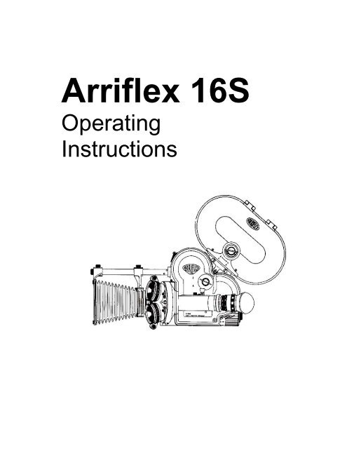
<strong>Arriflex</strong> <strong>16S</strong><br />
Operating<br />
Instructions
1 Film Magazine (200 ft.)<br />
2 Magazine Cover Lock<br />
3 Latch for Magazine Lock<br />
4 Camera Cover Lock<br />
5 Diopter Adjustment Ring<br />
6 Eyepiece Retaining Ring<br />
7 Lock for Diopter Adjustment<br />
8 Power Cable Lock<br />
9 Override Button for Buckle Switch<br />
10 Camera “ON” Switch<br />
11 Camera ”OFF” Switch<br />
12 Cover Lock Spring<br />
13 Magazine Opening Cover<br />
14 Tachometer<br />
15 Footage Counter<br />
16 Frame Counter<br />
17 Power Connector<br />
18 Viewfinder Cover Door<br />
19 Accessory Shoe<br />
20 Focusing Lever<br />
21 Contour Hand Grip<br />
22 Re-Set for Footage Counter<br />
23 Re-Set for Frame Counter<br />
24 Motor Lock Lever<br />
25 Variable Speed Motor<br />
26 Rheostat To Control Camera Speed<br />
27 Inching Knob<br />
28 Eyelet for Carrying Strap<br />
29 Knurled Dis, Camera Take-Up<br />
30 Locking Levers for Torque Motor<br />
31 Torque Motor<br />
32 Knurled Disc, Magazine Take-Up<br />
33 Film Supply Counter<br />
34 Forward/Reverse Switch for Torque Motor<br />
35 Knurled Disc, Magazine Supply<br />
36 Knurled Disc, Camera Supply<br />
37 Lens Turret<br />
38 Lens Retaining Lever<br />
39 Filter Stage, Rotating<br />
40 Filter Stage, Stationary<br />
41 Matte Slot<br />
42 Matte Box<br />
43 Matte Box Beam<br />
44 Lock Screw for Matte Box<br />
45 Lock Screw for Matte Box Stages<br />
46 Diaphragm Ring<br />
47 Turret-Rotating Grips<br />
48 Eyelet for Carrying Strap
The <strong>Arriflex</strong> <strong>16S</strong>/B-GS<br />
[With 60-Cycle Generator and<br />
Automatic Startmarker]<br />
The <strong>16S</strong> /B-GS is a special model of<br />
the basic Arrilflex 16 S/B. It is factory<br />
equipped with a 60-cycle generator, an<br />
automatic startmarker and a manually<br />
operated cue marker, designed to<br />
work with all ¼” tape recorders<br />
equipped with the pilotone system.<br />
The 60-Cycle Signal Generator<br />
A miniature generator is built into the<br />
camera. When the camera runs at 24<br />
fps, the generator ooutput is a 60-cycle<br />
signal of approximately 1.2 volts. This<br />
signal is the heart of all Piloton<br />
synchronizing systems. The output<br />
appears across pins 1 and 2 of the<br />
camera’s 5-pin Tuchel outlet, after a<br />
300 milli-second delay. Sync cables<br />
are used to carry this signal to the tape<br />
recorder. (See price list for various<br />
types).<br />
Automatic Clapstick<br />
The 16 S/B-GS has an automatic startmarker capable of putting startmarks<br />
on the film and on the tape, automatically, each time the camera is<br />
started.
The miniature lamp, which is visible just over the camera hand grip is paired with<br />
another lamp, located inside the camera. The inside lamp flashes whole frames<br />
of film, during camera run-up time. The result is that the beginning of each take,<br />
three or four frames of film are flashed. The start mark on the tape corresponds<br />
with the point just past the last flashed frame on the film. Light from the interior<br />
marking lamp in visible in the viewfinder, during run-up time. Note that the lamps<br />
are activated only when a properly wired cable is plugged into the 5-pin Tuchel<br />
outlet.<br />
To remove the start marking lamps for<br />
replacement, turn the plastic housing on<br />
its metal base counterclockwise. The pair<br />
of lamps are secured to the ends of the<br />
black rod (P1) which may be lifted out.<br />
These lamps are resistance matched<br />
pairs, and must always be replaced with a<br />
new, matched pair.<br />
8 Volt DC Output<br />
At the same time, during which the start mark lamps are energized, the camera<br />
will supply 8 volts DC through pin 3 on the Tuchel outlet. (See schematic).<br />
This voltage energizes a 1000 cycle oscillator built into the tape recorder. The<br />
1000 cycle signal is recorded on the tape and serves as a start-mark in the<br />
sound track. The oscillator is cut off simultaneously with the marking lamps in<br />
the camera. Therefore, the point where the 100 cycle signal ends on the tape,<br />
corresponds with the point where the flashed frames end on the film and<br />
constitute the sync point.<br />
Edge Marking System<br />
The edge-marking lamp is mounted in the<br />
base of the camera under the coin slotted<br />
contact screw. The mating indicator lamp<br />
for edge marking is located on top of the<br />
small generator casting on the right side<br />
of the camera. These lamps are also a<br />
matched pair and should be replaced with<br />
matched pairs.<br />
At the start of a take, the edge-marking lamps work simultaneously with the full<br />
frame marking lamps. However, these lamps mark the film at the edge only, and<br />
the edge marking is displace on the film by about 3 ½ frames from the aperture in<br />
direction of travel. The edge-marking lamp can be energized manually during a<br />
take for event marks of various kinds.
<strong>Arriflex</strong> <strong>16S</strong><br />
Operating Instructions<br />
Each <strong>Arriflex</strong> 16 S/B is SUPPLIED WITH:<br />
1 Test film taken with camera<br />
2 Plastic skewer for cleaning emulsion from film gate.<br />
3 Bottle with special camera oil<br />
4 Tube of special grease for lens cavities of camera and lens mounts.<br />
5 Pressure Oiler<br />
6 Guarantee Card<br />
7 Instruction Manual<br />
The shipping container in which the camera is supplies should be saved<br />
and used in case the camera has to be sent for service.<br />
NOTE: Numbers in ( ) refer to callouts on front overleaf.<br />
Holding the Camera<br />
Place thumb of right hand between<br />
contour grip (21) and side of camera,<br />
while the other fingers reach forward<br />
around the “bulge” so they are free to<br />
actuate the follow-focus grips (38) and<br />
diaphragm ring of the lens in taking<br />
position. Place palm of left hand<br />
around finder housing on left side of<br />
camera, fingers over ON-OFF switch<br />
this way, camera can be held steady<br />
and comfortably.<br />
When the “ON” switch (10) is pressed<br />
down, it remains locked in the downposition<br />
until the release lever (11) is<br />
pushed in.<br />
An accessory PISTOL GRIP WITH OR WITHOUT SHOULDER BRACE IS ALSO<br />
AVAILABLE. It is attached to the tripod socket in the base of the camea and has<br />
its own release trigger which activates a switch inside the tripod socket.
Viewing<br />
Place eye against finder eyecup.<br />
(Eyeglass wearers should remove or<br />
raise glasses to forehead and sight<br />
without them). For left eye viewing, the<br />
eyecup can be rotated. A periscope<br />
finder can be used for left eye viewing<br />
when a magazine is attached to the<br />
camera.<br />
If viewing is obstructed by the closed<br />
mirroe shutter, turn the inching knob (27)<br />
on the motor to open the viewing system.<br />
First focus your eye to the ground glass<br />
or fiber screen by turning the knurled<br />
diopter adjustment ring (5) at the<br />
eyepiece until the grain structure of the<br />
ground glass appears sharp. You best<br />
do this without a lens in the turret socket. The adjustment ring (5) should then be<br />
secured with the diopter lock ring (7). This setting need never be changed<br />
unless other persons use the camera. Once proper finder focusing is obtained,<br />
you can focus on a subject by actuating the focusing mount of the lens. For<br />
critical sharpness, always focus the lens with its diaphragm wide open.<br />
While the optical system of the finder is constructed so that it prevents light from<br />
entering and fogging the film, the eyepiece must be shielded from direct<br />
(horizontal) sunlight or powerful back light when the eye is removed from the<br />
eyepiece. For this purpose a light cover (18) is provided inside the rubber<br />
eyecup. During filming always press eye firmly against eyecup or close the cover<br />
door (18) on the eyepiece. The automatic eyepiece, available as an option, will<br />
close the reflex finder system anytime pressure against the eyecup is removed.
Detachable Eyepiece<br />
The detachable eyepiece, the same on<br />
all <strong>Arriflex</strong> cameras, permits the use of a<br />
variety of finder accessories like the<br />
PERISOPIC ACCESSORY FINDER,<br />
WHICH FACILITATES VIEWING FROM<br />
THE SIDE OR THE TOP (for instance if<br />
camera is on a microscope or copy<br />
stand), or viewing with the left eye when<br />
a 400 ft. MAGAZINE is attached to the<br />
camera. A finder extender can also be<br />
mounted when working in unusual<br />
situation.<br />
To remove the eyepiece, turn the knurled chrome-plated collar (6) clockwise. To<br />
re-mount it, first engage the keyed flange properly then turn the collar (6)<br />
counterclockwise. Exercise care not to cross thread the collar and make sure the<br />
eyepiece is flush against the finder flange.<br />
The rubber eyecup swivels freely in its ball-stop bearing and can be pulled off for<br />
cleaning. The installation of a prescription corrective lens – of 15.5mm diameter<br />
– is possible in a specially provided recess in the eyecup assembly.<br />
Ground Glasses/Fiber Screens<br />
The standard ground glass, supplied with the camera, is marked to show: center<br />
cross, TV safe action and camera aperture. It can be interchanged for a special<br />
ground glass with center cross and projector aperture only, or for a clear glass<br />
with reference reticle for cinemicroscopy. (See price list for details.) Such<br />
installations must be done only by skilled, <strong>Arriflex</strong> trained technicians and require<br />
special tools.
All 16 S cameras equipped with APEC have the new fiber screen in place of a<br />
ground glass. The fiber screen has distinctly greater brilliance, which is<br />
especially noticeable in low light conditions or at small lens apertures. Fiber<br />
screens are available for later installation in any <strong>Arriflex</strong> <strong>16S</strong> above serial number<br />
8981. On <strong>Arriflex</strong> <strong>16S</strong> cameras with Serial Number 6101 to 8980,<br />
exchangeability of the ground glass to fiber screen is possible by using a finder<br />
modernization kit (see price list for details).<br />
The Three Lens Divergent Turret<br />
The <strong>Arriflex</strong> 16 features a heavy-duty three-lens turret (37). The lenses are<br />
mounted in a divergent manner of 21o to prevent optical and mechanical<br />
interference between wide-angle and telephoto lenses.<br />
A turret lock prevents the turret from being turned unintentionally. To lock the<br />
turret, be sure the taking lens is precisely located by the turret detent<br />
mechanism, then turn the lock lever clockwise as far as it will go. (See<br />
illustration 6). To open the turret lock, turn th elever counterclockwise. Three<br />
turret grips (47) make it easy to rotate the selected lens into taking position.<br />
Always turn the turret by means of the grips, never by the lenses.<br />
The back of each turret grip (47) is coded with either one, two or three dots.<br />
These dots can be seen from the rear, while filming and can therefore be used to<br />
indicate if the wide angle, normal or telephoto lens is in taking position.<br />
Standard Lens Mounts<br />
Two of the three lens cavities are for<br />
standard <strong>Arriflex</strong> lens mounts. These<br />
are ideal for fixed focal length lenses or<br />
average size. To seat lenses in standard<br />
Arri mounts: Press the pair of lens<br />
locking levers (38) together, align the<br />
keyway in the lens mount with the key in<br />
the socket and carefully place the lens in<br />
the socket. When the lents is seated,<br />
release the lock levers, and check that<br />
the lens is locked safely in place.<br />
Always keep lens mount and lens socket<br />
lubricated with a trace of the instrument<br />
grease supplied with your camera.<br />
To remove standard Arri mounted lenses: Press the lens locking levers (38)<br />
together, then lift the lens straight out. Always keep empty lens cavities covered<br />
with cavity caps.
Bayonet Lock Lens Mounts<br />
One of the three lens sockets is for lenses in Bayonet Lock Mounts. This stronger<br />
mount, is primarily intended for zoom lenses or other larger, heavier lenses.<br />
To seat Bayonet Lock Lenses: Note the locking lugs at the rear of the lens mount<br />
-position the lens so the lens data engravings are on the top, and the lugs are in<br />
line with the keyways in the socket. (See illustration). Insert the lens as far as it<br />
will go and then twist the entire lens clockwise by 15°. You will hear and feel the<br />
mount latch into place. The lens locking levers (38) operate automatically in this<br />
case and need not be depressed.<br />
To remove Bayonet Lock Lenses: Press the Locking Levers (38) together, rotate<br />
the lens counterclockwise. Then lift the lens out of the cavity.<br />
Always try to hold the lens on a fixed part of the barrel. Don't rotate the lens for<br />
mounting purposes by the focusing or iris rings. The Bayonet Lock mount<br />
provides seating and lens alignment of superior precision and durability. Use<br />
zoom lenses always in Arri Bayonet Lock Lens Mounts.<br />
Lenses for <strong>Arriflex</strong> are made by the<br />
world's leading optical manufacturers<br />
and represent the ultimate in optical<br />
and mechanical quality. Lenses<br />
available for the <strong>Arriflex</strong> 16 range in<br />
focal length from 5.7mm on up.<br />
Standard lenses are equipped with<br />
follow-focus grips (20) and most have<br />
diaphragm click-stops. Use only<br />
lenses in genuine <strong>Arriflex</strong> lens mounts<br />
to insure trouble-free operation and<br />
optimum image quality. For extremely<br />
long or heavy lenses, lens support<br />
systems of various types are<br />
available, the most practical of which<br />
is the standard ARRIFLEX bridge<br />
plate system.
Standard Matte Box and<br />
Filter Holder<br />
To attach the matte box to the camera,<br />
slide the end of the boom into the special<br />
shoe (19) on the front of the camera<br />
housing. Lock it into position by turning<br />
the knurled (44) knob at the front of the<br />
boom.<br />
The rear stage of the matte box is<br />
adjustable to accommodate lenses of<br />
various lengths. The front is adjustable<br />
for optimum protection from side light<br />
and to prevent vignetting irrespective of<br />
lens focal length.<br />
SPECIAL EFFECT MATTES such as<br />
key holes, binoculars, etc. can be<br />
inserted into a slot in the front frame.<br />
Two filter stages accept rectangular 60x75mm and 60x100mm GLASS FILTERS,<br />
or ARRI FILTER HOLDERS with frame for 2" square gelatine or glass filters. One<br />
of the stages can be rotated for use with GRADUATED OR POLARIZING<br />
FILTERS. (For filter listing see separate filter price list). The rear opening of the<br />
matte box is threaded to accept a screw-in adapter ring for Series 8 mounted<br />
filters.<br />
Universal Matte Box<br />
The Universal Matte Box, especially designed for Zoom lenses also<br />
accommodates many standard and telephoto fixed focal length lenses. Features<br />
include adjustable front and rear standards, two filter stages, one of which may<br />
be rotated for polarizing filters. 3"x3", 75mmx100mm graduated filters, and 4"x4"<br />
filters can be used.
Motors<br />
The 8 Volt VARIABLE SPEED MOTOR<br />
is generally standard equipment for<br />
<strong>16S</strong>/B. All motors are interchangeable.<br />
By simply opening lock lever (24), the<br />
motor may be pulled out of the camera<br />
housing and replaced with any other<br />
motor such as -GOVERNOR<br />
CONTROLLED CONSTANT SPEED<br />
MOTOR, 110V 60 HZ SYNCHRONOUS<br />
MOTOR, ANIMATION MOTOR and<br />
UNIVERSAL CRYSTAL CONTROLLED<br />
MOTOR. When mounting a motor, care<br />
must be taken to line up the locating pin<br />
with the keyway in the camera and to<br />
insert the motor, all the way into the<br />
motor cavity to insure proper electrical<br />
contact.<br />
Variable Speed Motors<br />
By turning ribbed motor housing, a rheostat is actuated to regulate the speed of<br />
the motor. The figures around the motor shell are arbitrary, however, after some<br />
experience, they permit the operator to reset the camera quickly for any desired<br />
speed. (With, a full charged 8 Volt battery the rheostat will be set between 3 and<br />
4 to give 24 fps.<br />
A knurled disc (see Illustration) marked<br />
"R"-"F" is located at the back of the<br />
variable speed motor. When turned all<br />
the way to "F" (click stop), the camera<br />
will run Forward; turned to "R" (clickstop),<br />
the camera will run in Reverse.<br />
When using a magazine, both, camera<br />
motor and magazine torque motor,<br />
must be set to run in the same<br />
direction, i.e. BOTH forward or BOTH<br />
reverse!<br />
The inching knob (27) in the center of the motor is used to turn the shutter and<br />
actuate the registration pin and film transport claw during the film loading<br />
operation.<br />
Constant Speed Motor<br />
The constant speed motor is used when only one single camera speed<br />
(24/25Fps) is required. In size and shape similar to the variable motor, the<br />
constant speed motor uses a centrifugal switch (governor) to keep the motor<br />
speed accurate within 1% under varying load and power conditions. The motor<br />
runs forward only and requires an 8V DC power source.
Power Sources/Batteries<br />
Power requirements for <strong>Arriflex</strong> 16 with variable speed or constant speed motor<br />
and with 400 ft. magazine are:<br />
8 Volts DC (under load); 3.6 Amperes running; starting surge up to 6 Amperes<br />
depending on ambient temperature and condition of equipment.<br />
For the crystal controlled motor, 12VDC is required. Be sure the magazine torque<br />
motor is a 12V version when using the crystal motor with 400 ft. magazine. (See<br />
special instructions.)<br />
<strong>Arriflex</strong>-made batteries are available in a wide variety of sizes, power output and<br />
connections. You may use any suitable power supply which is capable of<br />
delivering the required voltage and amperes. Generally, batteries with less than<br />
1.8 Ampere/hours at rated voltage are not practical.<br />
In an emergency, the <strong>Arriflex</strong> <strong>16S</strong> may be operated from a 6 Volt auto battery.<br />
Maximum camera speed will be approximately 24 FPS with the variable speed<br />
motor. A 12 Volt auto battery may generate excessive torque unless the battery<br />
is tapped for 8 Volts. MAKE CERTAIN PROPER POLARITY IS MAINTAINED.<br />
To use any <strong>Arriflex</strong> DC motor on 110 Volt AC current, a power supply with<br />
transformer and rectifier is necessary. (See <strong>16S</strong> price list).<br />
Camera Tachometer & Film Counter<br />
The <strong>Arriflex</strong> <strong>16S</strong>/B is equipped with a tachometer (14), which registers filming<br />
speeds from 5 to 50 frames per second.<br />
It registers forward speeds only. The camera should never be run above the<br />
maximum speed indicated by the tachometer.<br />
Below the tachometer are the film footage counter (15) and frame counter (16).<br />
Both can be zeroed easily by their respective setting discs (22/23).<br />
Film Gate<br />
The <strong>Arriflex</strong> film gate is extra long (3 inches) and has a full-length rear pressure<br />
pad with a side pressure rail. Cross stages around the picture frame both on the<br />
front and back plates prevent "film breathing". Made of stainless steel, tapped to<br />
high precision and wear chrome-plated, the <strong>Arriflex</strong> film gate is probably one of<br />
the most trouble-free yet highest quality film gates of any camera. It is important<br />
to clean the gate regularly of film emulsion and film base deposits.<br />
Never use any metal tools on the gate surfaces! Use only the plastic<br />
skewer supplied with the camera and a clean untreated optical cloth.
Registration Pin<br />
With the film gate opened, the registration pin can be seen just above the<br />
transport claw. Its function is to locate the film precisely and to hold it in place<br />
during the moment of exposure. The registration pin ensures rock-steady<br />
pictures, a repetitively precise film line, and increased tolerance against film pitch<br />
changes. Never force the registration pin in any way while cleaning the<br />
gate, only activate it by turning the motor inching knob [27].<br />
Film Transport Claw<br />
The film transport claw engages the film from the front, the emulsion side. Watch<br />
its action by turning the inching knob (27) and note that it engages the film while<br />
the registration pin is lifting out of the perforation. This way, during the entire<br />
frame cycle, there is always one claw engaged for positive control of film.<br />
Mirror Reflex Shutter<br />
The mirror reflex shutter is the heart of<br />
the <strong>Arriflex</strong> reflex system. It rotates at a<br />
45° angle between lens and film plane<br />
and reflects to the ground glass of the<br />
viewfinder exactly the same image as is<br />
registered on the film. All of the light rays<br />
reach the film through the lens without<br />
any interference while the shutter is<br />
open, and are alternately reflected to the<br />
ground glass only while the shutter is<br />
closed. Thus the film, as well as the eye,<br />
always gets 100% of the light transmitted<br />
by the taking lens.<br />
The effective shutter opening is 180° and<br />
gives the following exposure times at<br />
various speeds:<br />
8 FPS – 1/16 sec. 12 FPS – 1/24 sec. 16 FPS – 1/32 sec.<br />
24 FPS – 1/48 sec. 32 FPS – 1/64 sec. 48 FPS – 1/96 sec.<br />
As this table indicates, the exposure can be calculated for the camera speed by<br />
doubling the FPS figure and reading the result as a fraction of a second (180°<br />
shutter only).<br />
Tripod Sockets<br />
Two tripod threads, one 1/4" and one 3/8" size, are provided in the bottom of<br />
camera housing. This socket is made of tool steel and is a replaceable insert in<br />
the aluminum camera housing.<br />
Many standard tripod screws might be too long and trigger the built-in<br />
switch for the pistol grip. An excessively long tripod screw could even<br />
damage the switch housing inside the camera. The standard length for<br />
tripod screw is 7mm = 0.280 inches.
Camera Loading & Threading<br />
Turn cover lock (14) from “C” to “O” and lift cover. Lay cover down and be sure<br />
switch is in OFF position otherwise switch activating pin could get bent. Place<br />
100 ft. film spool on upper spindle. Pull off about 2 feet of film. Both spindles<br />
have an automatic lock to hold film spool in place in any camera position. To take<br />
film spool out, push button in center of spindle and tilt camera sideways.<br />
Open film gate by pressing latching knob<br />
inwards and swing the pressure pad<br />
assembly open on its hinges. Before<br />
threading film, open pressure roller assembly<br />
A by pressing button B. Thread film around<br />
sprocket drum C. Swing off pressure roller 0-<br />
1, if necessary. Then arrest film by swinging<br />
back pressure roller D-1. Lead film to gate E<br />
by forming an upper loop according to<br />
marking in the camera body above the film<br />
gate. Register pin F must be in disengaged<br />
(up) position. If it is not, turn motor inching<br />
knob (27) until pin is lifted over the film guide.<br />
Place film into gate in such a way that a perforation hole engages the protruding<br />
film transport claw. Hold film down with two fingers, one at either end of the gate<br />
and turn inching knob (27) until the registration pin engages film and holds it in<br />
place. Be sure film lays flush down against the aperture plate, then close gate.<br />
Thread film around sprocket drum G, forming a lower loop according to the<br />
marking in the camera body below the gate, and close pressure roller D2, At this<br />
point the roller assembly A should be securely closed.<br />
The sprockets are designed to accept either single or double perforated<br />
film. It is important to set film properly by moving it back and forth with two<br />
fingers over each sprocket until you can feel that the sprocket teeth have<br />
engaged the perforations. Push the leading end of the film into the take-up slot<br />
of an empty 100 ft. daylight spool and secure it by a few turns. Place the spool on<br />
the take-up spindle and be sure it "'snaps" into place securely.<br />
The knurled spindle discs (28,36) outside of the camera serve to take up film<br />
slack by turning them in direction of the engraved arrows.<br />
When the film is running, these discs turn and indicate whether film goes forward<br />
or backward. When film has run off, the supply spindle stops turning thus<br />
indicating the end of the film in the event the buckle switch is not functioning.<br />
Prior to switching camera "ON" or closing the cover, move a few inches of<br />
film through gate by manually turning inching knob [27] clockwise.<br />
With camera connected to power, push down internal switch (K) and watch about<br />
2 feet of film roll through the camera. (Note: A "100 ft. roll" of film on a daylight<br />
loading spool actually measures 106 feet to permit enough leader and trailer.)
Then close camera and turn lock (4) to "C", Again, be sure that the door switch<br />
(10) is released, in the "OFF" position, otherwise the cover cannot be closed.<br />
Run off approximately 5 feet of light-struck leader before beginning filming.<br />
Set footage counter and frame counter to –0– by rotating the discs (22/23)<br />
next to the plexiglass windows.<br />
Buckle Switch With Manual Override<br />
The buckle switch (film end switch H) works properly only if the lower film loop is<br />
formed exactly according to the marking in camera body. When the end of the<br />
film has passed the film gate, the lower loop shortens, thereby pulling up the<br />
switch roller H, which in turn cuts off the camera motor. The camera can only be<br />
switched on again after the pressure roller assembly A has been opened and<br />
closed as described in the previous paragraph. The buckle switch also stays<br />
"OFF" in the event that the pressure roller assembly A is not closed properly, i.e.,<br />
the camera will not start. Any shortening of the lower loop during the running of<br />
the camera actuates the buckle switch to prevent film jamming.<br />
Never actuate or force the switch roller H by hand!<br />
The buckle switch override button (9) underneath the finder tube permits the<br />
cameraman to circumvent the buckle switch circuit. On certain adverse and rare<br />
occasions, particularly due to heavy-duty shock or vibration, the micro switch of<br />
the buckle switch might trip and switch the camera off. With the override<br />
mechanism the cameraman can quickly restart the camera without opening the<br />
camera cover.
However, when in doubt whether the buckle switch was unintentionally triggered<br />
by impacts or vibration, or whether it was actuated due to a film jam, it is<br />
recommended to open the camera, to check the film path and<br />
sacrifice a few inches of film rather than risk damage by just using the external<br />
override control.<br />
To do this, it is recommended that the cameraman push the override button and<br />
run the Camera just long enough to keep the end of the last exposed scene from<br />
becoming light struck when the camera door is opened. Then, stop the camera,<br />
open the camera door, check for and correct any malfunction, reset the buckle<br />
trip mechanism, reset the buckle override, (see following instructions), close the<br />
camera door, run-off light struck footage and continue.<br />
Finally, once the override (9) has been used, it will have to be reset so the buckle<br />
switch can be reactivated.<br />
To reset the override, the toggle lever U of the buckle switch override<br />
mechanism must be turned counterclockwise approximately 45° from its off<br />
position. This shuts off the override function.
Magazine<br />
The top of the camera housing accepts the 400 ft. film magazine. A light-tight<br />
cover (13) protects the magazine slot. Before the magazine can be attached,<br />
remove the cover by pulling firmly on this latch (12). The camera housing is<br />
internally wired to supply power to the take-up motor. The contact is visible once<br />
the cover is pulled off. This power contact is silver-plated and must be kept clean<br />
at all times to insure lowest resistance.<br />
<strong>Arriflex</strong> <strong>16S</strong> magazines are designed for 400 ft. and 200 ft. 16mm single or<br />
double perforated film on plastic core (darkroom loads) B-wound. By removing<br />
the core adapters, the 400 ft. magazine will also accept 200 ft. daylight loads on<br />
spools.<br />
Magazine Loading<br />
The following procedure must be done in total darkness when using core<br />
load film.<br />
To open magazine cover, depress the safety latch (leaf spring) and turn lock (2)<br />
counterclockwise to its stop. Swing supply guide arm up until it is arrested near<br />
top casting of magazine. With leading end of film unwinding clockwise, place roll<br />
on left spindle by pushing plastic film core onto core adapter. Do not "dish" the<br />
film by pushing down on the outer diameter of the roll! Unlatch supply guide arm<br />
and be sure the flanges of the roller slip over the film edges and guide it properly.<br />
Now slip the leading end of the film through the left hand slot between the light<br />
trap rollers until it exists on the outside of the magazine throat. Then reverse this<br />
procedure and push the film back into the compartment by feeding it through the<br />
take-up slot which is on the other side of the throat from where the film exited.
Once back in the compartment, arrest the take-up guide arm in it's latch near the<br />
top of the magazine casting. Attach the film to the collapsible core by slipping it<br />
into the gap and locking it with the chromed expansion clip.<br />
During unloading, when using a collapsible center core, the film can easily<br />
unspool from the center unless it is deliberately held. It is recommended<br />
that a plastic core be inserted before repacking the film for the lab. By<br />
twisting the plastic core a few turns in the direction of the film wind it will<br />
"grab" the trailing end of the film and hold securely.<br />
Collapsible Core Standard Core Core Adapter<br />
Each one of the core adapters is easily interchangeable by depressing the<br />
buttons at the ends of the film spindles. A standard core adapter can be<br />
substituted for the collapsible one on the take-up side. In this case, a regular<br />
plastic film core would have to be used on the take-up side as well.<br />
Once the film loading procedure is<br />
completed, close the magazine by<br />
engaging the two location prongs on the<br />
bottom of the cover in the corresponding<br />
grooves of the magazine casting. Then<br />
lay the cover flush against the magazine<br />
and turn the lock clockwise until the<br />
safety latch "clicks" into position.<br />
Important Points To Check<br />
Attach the film on the supply and take-up cores so it will run freely without<br />
"wobble" inside the guide arm rollers.<br />
Be sure to release both guide arms before closing the magazine cover. The<br />
supply guide arm activates the film supply counter on the outside of the<br />
magazine! If not released, the counter will not indicate.
Wind sufficient film onto the take-up core to be certain It won't slip, that it<br />
will wind even and in line with the guide roller. Always be sure to remove<br />
the core adapter from the exposed roll before repacking film for the lab.<br />
Many adapters have been lost this way. Practice the Ioading with outdated<br />
film, in the light, a few times and these procedures will quickly become<br />
routine.<br />
The <strong>Arriflex</strong> <strong>16S</strong> has the sprocket drive in the camera compartment. To load the<br />
camera with a pre-Ioaded magazine, proceed as follows:<br />
Pull enough film out of the throat of the magazine so you can guide it through the<br />
magazine opening on the camera casting. Then engage the dovetail wedge on<br />
the rear of the magazine in the corresponding<br />
wedge on the camera, lift the magazine lock<br />
(3) which contracts the locking wedges and<br />
lower the front wedge into the camera<br />
casting. With the magazine loosely seated in<br />
the camera casting, pull the latch (3) of the<br />
magazine lock down and the resulting<br />
expansion of the wedges will secure the<br />
magazine to the camera. To prevent an<br />
accidental releasing of the lock, always hook<br />
the safety catch into the lock latch.<br />
With the magazine safely mounted on the camera, proceed with the film loading<br />
in the same manner as described previously for 100 ft. camera loads.<br />
Torque Motor<br />
The magazine take-up motor, torque motor, attaches to the body of the magazine<br />
by means of two lock levers (30) and becomes an integral part of it.<br />
To attach the torque motor to the magazine,<br />
both levers (30) are turned upward, the<br />
motor is pressed against the corresponding<br />
area of the magazine and then both levers<br />
(30) are turned in direction of the arrows<br />
until they are reasonably tight.<br />
In the center of the torque motor casting is<br />
the lever (34) which controls the<br />
forward/reverse running of the magazine. It<br />
is important that the setting of this lever<br />
corresponds with the directional setting of<br />
the camera drive motor.
Prior to filming with a freshly loaded magazine always turn the two knurled knobs<br />
(32,35) on the torque motor in the directions indicated by the arrows to remove<br />
excessive film slack in the magazine.<br />
All later model torque motors are equipped<br />
with a grounding plug for a small wire,<br />
which leads directly from the negative pole<br />
of the battery cable to the torque motor.<br />
The most probable cause of torque motor<br />
failure is the lack of sufficiently good<br />
ground contact and the use of this wire is<br />
recommended at all times. Older torque<br />
motors can be retrofitted with this feature.
Servicing and Maintenance<br />
The <strong>Arriflex</strong> <strong>16S</strong> is built with utmost precision and is famous for its<br />
ruggedness. It will give absolute satisfaction if treated as any precision<br />
instrument should be treated, and if serviced at regular intervals, consistent<br />
with the amount of use, and the following recommendations.<br />
The most important rule is:<br />
KEEP THE CAMERA SPOTLESSLY CLEAN – INSIDE AND OUT!<br />
Particular attention must be given to the film gate. It is precision-lapped and<br />
chrome-plated to minimize film emulsion to settle. However, some emulsion<br />
deposit is inevitable and will vary with the type of film used, the relative<br />
humidity and other factors.<br />
The film gate should be checked and cleaned every 400 ft. roll and it<br />
should be carefully inspected and thoroughly cleaned at the end of each<br />
day's filming. Remove emulsion deposit with the plastic skewer supplied<br />
with the camera (NEVER METAL). If emulsion is hardened on film gate,<br />
remove it with a Q-tip dipped in acetone or alcohol. Be careful not to get<br />
any solvent on any optical surface. Acetone will also dissolve paint. After<br />
cleaning, polish gently with chamois or other soft, clean optical cloth.<br />
From time to time, the lens mounts and the three lens sockets in the turret<br />
should be cleaned to remove dirt and dust. After such cleaning, re-lubricate<br />
lightly with the special grease supplied with the camera.<br />
The standard lubricants used with the <strong>Arriflex</strong> are suitable for use in<br />
temperatures down to -20°C, provided the camera is in good working<br />
condition, and the lubricants in the camera mechanism itself are clean and<br />
uncontaminated by dirt.<br />
On special request and for extra charge, <strong>Arriflex</strong> cameras can be winterized<br />
at our Service Department to function at still lower temperatures. For<br />
details, consult section on "low temperature operation."<br />
Lubrication<br />
Your camera has been properly lubricated at the factory and is ready for<br />
operation. Do not oil before using unless camera had been stored and<br />
not been used for more than 12 months.<br />
After each run of 30,000- 50,000 feet of film through the camera, camera<br />
should be lightly oiled at two oil valves marked with arrows (one near the<br />
film gate, and one near the supply spindle). Only use the ball and pressure<br />
oiler supplied with your camera and the special oil contained therein. Do<br />
not overoil -too much oiling is as bad as too little!
By observing the following "DON'Ts” you will protect the continued safe and<br />
reliable operation of your <strong>Arriflex</strong>:<br />
DON'T run camera without film at high speeds.<br />
DON'T attempt to disassemble any part of the camera. This should be<br />
done by factory-trained personnel only.<br />
DON'T touch mirror shutter with fingers. Clean it only with soft camel hair<br />
brush. In any case, a spot on the mirror does not affect the picture.<br />
DON'T exchange covers of different camera (serial numbers are engraved<br />
on each coyer and camera).<br />
DON'T use old or shrunk film; the registration pin's stroke is adjusted to the<br />
perforation pitch of fresh film (0.2994) according to ASA specifications.<br />
DON'T allow cameras to be serviced by unqualified service shops. <strong>Arriflex</strong><br />
cameras require special knowledge and experience.<br />
DON'T neglect to have your camera serviced after approximately every<br />
200,000 ft., or every two years, whichever comes first. Service should be<br />
more frequent under adverse conditions.<br />
Our Service Department welcomes your inquiries and is anxious to help<br />
you with any problem or unforeseen requirements you might have.