Raptor 700R Dyna FS Ignition (06-10) - Two Brothers Racing
Raptor 700R Dyna FS Ignition (06-10) - Two Brothers Racing
Raptor 700R Dyna FS Ignition (06-10) - Two Brothers Racing
- No tags were found...

You also want an ePaper? Increase the reach of your titles
YUMPU automatically turns print PDFs into web optimized ePapers that Google loves.
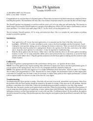
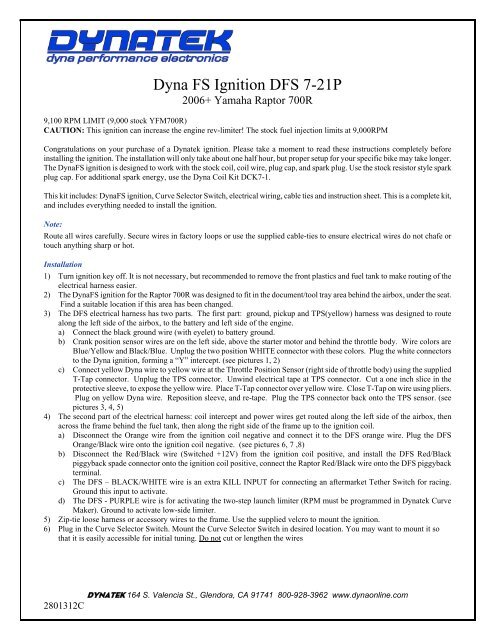
<strong>Dyna</strong> <strong>FS</strong> <strong>Ignition</strong> D<strong>FS</strong> 7-21P20<strong>06</strong>+ Yamaha <strong>Raptor</strong> <strong>700R</strong>9,<strong>10</strong>0 RPM LIMIT (9,000 stock YFM<strong>700R</strong>)CAUTION: This ignition can increase the engine rev-limiter! The stock fuel injection limits at 9,000RPMCongratulations on your purchase of a <strong>Dyna</strong>tek ignition. Please take a moment to read these instructions completely beforeinstalling the ignition. The installation will only take about one half hour, but proper setup for your specific bike may take longer.The <strong>Dyna</strong><strong>FS</strong> ignition is designed to work with the stock coil, coil wire, plug cap, and spark plug. Use the stock resistor style sparkplug cap. For additional spark energy, use the <strong>Dyna</strong> Coil Kit DCK7-1.This kit includes: <strong>Dyna</strong><strong>FS</strong> ignition, Curve Selector Switch, electrical wiring, cable ties and instruction sheet. This is a complete kit,and includes everything needed to install the ignition.Note:Route all wires carefully. Secure wires in factory loops or use the supplied cable-ties to ensure electrical wires do not chafe ortouch anything sharp or hot.Installation1) Turn ignition key off. It is not necessary, but recommended to remove the front plastics and fuel tank to make routing of theelectrical harness easier.2) The <strong>Dyna</strong><strong>FS</strong> ignition for the <strong>Raptor</strong> <strong>700R</strong> was designed to fit in the document/tool tray area behind the airbox, under the seat.Find a suitable location if this area has been changed.3) The D<strong>FS</strong> electrical harness has two parts. The first part: ground, pickup and TPS(yellow) harness was designed to routealong the left side of the airbox, to the battery and left side of the engine.a) Connect the black ground wire (with eyelet) to battery ground.b) Crank position sensor wires are on the left side, above the starter motor and behind the throttle body. Wire colors areBlue/Yellow and Black/Blue. Unplug the two position WHITE connector with these colors. Plug the white connectorsto the <strong>Dyna</strong> ignition, forming a “Y” intercept. (see pictures 1, 2)c) Connect yellow <strong>Dyna</strong> wire to yellow wire at the Throttle Position Sensor (right side of throttle body) using the suppliedT-Tap connector. Unplug the TPS connector. Unwind electrical tape at TPS connector. Cut a one inch slice in theprotective sleeve, to expose the yellow wire. Place T-Tap connector over yellow wire. Close T-Tap on wire using pliers.Plug on yellow <strong>Dyna</strong> wire. Reposition sleeve, and re-tape. Plug the TPS connector back onto the TPS sensor. (seepictures 3, 4, 5)4) The second part of the electrical harness: coil intercept and power wires get routed along the left side of the airbox, thenacross the frame behind the fuel tank, then along the right side of the frame up to the ignition coil.a) Disconnect the Orange wire from the ignition coil negative and connect it to the D<strong>FS</strong> orange wire. Plug the D<strong>FS</strong>Orange/Black wire onto the ignition coil negative. (see pictures 6, 7 ,8)b) Disconnect the Red/Black wire (Switched +12V) from the ignition coil positive, and install the D<strong>FS</strong> Red/Blackpiggyback spade connector onto the ignition coil positive, connect the <strong>Raptor</strong> Red/Black wire onto the D<strong>FS</strong> piggybackterminal.c) The D<strong>FS</strong> – BLACK/WHITE wire is an extra KILL INPUT for connecting an aftermarket Tether Switch for racing.Ground this input to activate.d) The D<strong>FS</strong> - PURPLE wire is for activating the two-step launch limiter (RPM must be programmed in <strong>Dyna</strong>tek CurveMaker). Ground to activate low-side limiter.5) Zip-tie loose harness or accessory wires to the frame. Use the supplied velcro to mount the ignition.6) Plug in the Curve Selector Switch. Mount the Curve Selector Switch in desired location. You may want to mount it sothat it is easily accessible for initial tuning. Do not cut or lengthen the wires2801312CDYNATEK 164 S. Valencia St., Glendora, CA 91741 800-928-3962 www.dynaonline.com
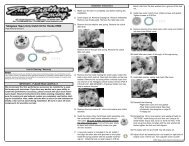
CalibrationThe <strong>Dyna</strong><strong>FS</strong> is programmed with 4 advance curves. A quicker throttle response and increased power over the stockcurve is achieved. For other advance curve information, see the attached Advance Chart.This ignition can potentially allow the engine to rev to a higher RPM, however, the STOCK EFI will limit the engine to9,000 RPM by shutting off the fuel injector. Because the rev limit can potentially be increased, the performance limits of otherengine parts (valvetrain or piston for example) may be found. It may be necessary to replace these parts for best engineperformance.Programmable ignitionsLap-top/PC Programmable versions (suffixed with a P in the part number) require a separate programming kit to reprogram them.It is not supplied with the ignition. If the programmable ignition was not purchased directly from <strong>Dyna</strong>tek, the dealer may haveprogrammed a custom set of ignition curves. The dealer should be consulted with any questions regarding the curves that areprogrammed into the ignition.Programmable ignitions are shipped with additional leads coming out of the ignition. These leads allow the ignition to controlother features. To program these features, follow the instructions in the programming kit.PURPLE – Programmable launch limiter. Ground this wire to activateBLUE – Optional 2-amp switch to ground, referenced as “RPM Switch 1” in PC Software.WHITE – Optional 2-amp switch to ground, referenced as “RPM Switch 2” in PC Software.The Launch RPM is programmable and can be wired to a separate clutch switch (not included) for a “two step/low side” launchlimiter. See attached wiring diagram for installation.The launch limiter has a one-time only activation. If the ignition detects the purple wire is grounded, then the ignition will not revpast the low-side limit. When the low-side rpm limit is detected, and the purple wire becomes ungrounded, then the launch limiteris defeated and will not work again until the power is cycled off and back on.The White & Blue 2-amp switches can be used to activate a solenoid or relay. Connect the relay with hot +12v wired to one sideof the relay coil, and the other side connected to White or Blue. When the rpm activates the switch, it will be grounded inside theignition box, causing current to flow through the relay coil. DO NOT connect any device which requires more than 2 Amps(Amps=Volts/Resistance). See attached wiring diagram for wiring the relay.TroubleshootingTroubleshooting the <strong>Dyna</strong> ignition is simple. If the bike will not start or run at all, disconnect the pickup intercept connector andconnect the <strong>Raptor</strong> Orange wire back to the ignition coil negative. If this fixes the problem, then the <strong>Dyna</strong> ignition should bereturned to <strong>Dyna</strong>tek for testing. If this does not fix the problem, then the problem is somewhere else on the bike. Follow thetroubleshooting procedures outlined in your bike shop manual.If you are using non stock spark plug, or stator, replace them with OEM units. Then follow the procedures in the calibrationsection to set the <strong>Dyna</strong> ignition up to work with your bike. If calibration doesn't fix the problem, the ignition should bereturned for testing. If the problem persists when using the stock ignition then the problem is external to the <strong>Dyna</strong> ignition.WARNING:Installation of a grounded tether kill switch to the ignition coil signalwill damage the CDI and void the warranty.12V Inductive <strong>Ignition</strong> (<strong>Raptor</strong> <strong>700R</strong>/etc.): For normally open tether switches: The simplestinstallation of this type of tether switch is to connect one kill wire to the External D<strong>FS</strong>BLACK/WHITEwire, and the other kill wire to chassis ground.To use a normally closed tether kill switch connected in series with the +12V input (RED/BLACK)to the ignition. When the tether is removed, it should disconnect the +12V power to the ignition.2801312C REV. 3-5-09DYNATEK 164 S. Valencia St., Glendora, CA 91741 800-928-3962 www.dynaonline.com2801312C
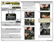
DYNA <strong>FS</strong> / YAMAHA RAPTOR <strong>700R</strong> - IGNITION CURVESPART-THROTTLECURVE1IGNITION ADVANCE(CRANKSHAFT DEGREES)CURVE4(STOCK)CURVE3RETARDCURVE2ADVANCEDWIDE OPENTHROTTLE(Curves 1-4)RPM / <strong>10</strong>00CURVE4 = STOCK ADVANCE(Assumes 9° base timing)2801312CDYNATEK 164 S. Valencia St., Glendora, CA 91741 800-928-3962 www.dynaonline.com
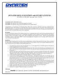
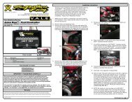
4-position connector forPC/Laptop programming3-position connector forCurve Selector Switch4 wires terminated withfemale bullet connectorsPURPLE = <strong>Two</strong>-step/low-side Launch Rev Limiter, requires a seperate switch (not included). Ground thiswire to activate the limiter. Use programming software to adjust the launch rpm.GREEN = Tach output, 1 pulse per rev, 12VBLUE = Programmable Speed Switch, 2 AMP MAX(referenced as "RPM Switch 1" in PC software)WHITE = Programmable Speed Switch, 2 AMP MAX(referenced as "RPM Switch 2" in PC software)NOTE1: White and Blue power switches can be programmed individually or together. Can be used to turnon a shift light, or activate a small solenoid, or switch a Bosch style relay for even heavier loads.NOTE2: The ignition will ground the White or Blue white inside the CDI when the pre-programmed RPMis achieved.2801312CDYNATEK 164 S. Valencia St., Glendora, CA 91741 800-928-3962 www.dynaonline.com
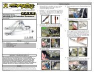
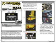
Picture1: Battery Ground.Picture2: Crank Pickup intercept connectors.Picture3: Expose the Yellow TPS signal wire.Picture4: Crimp the T-tap connector until it clicks.2801312CDYNATEK 164 S. Valencia St., Glendora, CA 91741 800-928-3962 www.dynaonline.com
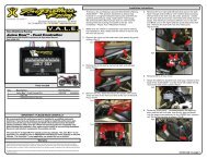
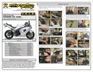
Picture5: Re-Tape the TPS connection.Picture6: Coil connections to stock ignition coil.Picture7: Coil connections to <strong>Dyna</strong>tek Coil(1)Picture8: Coil connections to <strong>Dyna</strong>tek Coil(2)2801312CDYNATEK 164 S. Valencia St., Glendora, CA 91741 800-928-3962 www.dynaonline.com