component troubleshooting guide - CCO Whirlpool and Spa Service
component troubleshooting guide - CCO Whirlpool and Spa Service
component troubleshooting guide - CCO Whirlpool and Spa Service
- No tags were found...

Create successful ePaper yourself
Turn your PDF publications into a flip-book with our unique Google optimized e-Paper software.
COMPONENTTROUBLESHOOTING GUIDECall us for your Jacuzzi ® part needs!1-888-JWB-PART (592-7278)REV: 03.01.2002Visit us on the web....http://www.jwbpart.comHave a parts list? Send us a fax.585-533-1349
COMPONENTTROUBLESHOOTINGGUIDEPRESSURE SWITCH (FLO SWITCH) ADJUSTMENTBALBOA CONTROLSThe electronic control systems on most Jacuzzi <strong>Whirlpool</strong> Bath <strong>Spa</strong>s manufactured after 11/94, utilizea pressure switch to determine flow "FLO" status of the water. This pressure switch condition is testedthrough-out the operation of the spa system.The check is to insure the pressure switch is Closed afterthe voltage has been supplied to the pump motor, <strong>and</strong> Open when the voltage is removed. If the switchreading by the control system is different than expected, an error message will appear on the DigitalControl Panel <strong>and</strong> the unit will stop operation. Sometimes this is a result of lessened water flow due toa dirty front load filter, while sometimes this is due to a switch being out of adjustment. The followingis a method of adjusting the pressure or "Flo" switch.1.) Locate the Pressure Switch on the back side of the stainless steel Heater Housing. The gray cablefrom the switch is connected to J3 (Platinum or Primer/Select) or J9 (Duplex).2.) Unplug the pressure switch from the circuit board <strong>and</strong> with a paperclip or pin knife, push out thetwo pins from the connector. Clip the leads from an OHM-METER onto these two pins.3.) With the system "OFF" <strong>and</strong> no voltage to the Pump/Motor the reading of the OHM-METER shouldbe on "OPEN". If the meter shows the switch as being "CLOSED" adjust the spoked wheel on thepressure switch counter-clockwise until an "OPEN" condition is read on the OHM-METER.4.) Start the <strong>Spa</strong> operation in a "Filter" mode <strong>and</strong> check the OHM-METER reading for a "CLOSED"switch reading. If the reading shows the switch to be in an "OPEN", turn the spoked wheel on thepressure switch clockwise until the meter reads "CLOSED" plus a little further to allow for a dirtyfilter.5.) Repeat Step #3. The OHM-METER should read "OPEN" with no power to pump/motor. NOTE: Besure all these adjustments are done in the low "Filter" mode <strong>and</strong> not the high-speed "Jet" operation.The pump/motor connection can be disconnected by unplugging the side motor connector while testingsteps #3 <strong>and</strong> #4.REV 03.01.2002Visit us on the web....http://www.ccowhirlpool.comTSG1Call us for your Jacuzzi ® part needs!1-888-JWB-PART (592-7278)
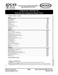
COMPONENTTROUBLESHOOTINGGUIDEMODELELECTRICAL COMPONENTSFUNCTION CHECKCOMPONENT TESTINGPART NO. DESCRIPTION TEST SPECIFICATIONS1865000 Relay, 30 AMP, DPST Coil: 12 VDC with 72 ohms resistance.(Quanta, Avanza, Cambio) Switch: check continuity across top with relay down.1872000 Full Wave Rectifier 4 Diodes: Check for continuity through each diode.(6 AMP) Reverse meter probes on each diode to assure continuity isin one direction only.1888000 Reed Switch Panel Check for continuity through each reed switch with control(Quanta)knobs in "ON" position. Turn control knobs to "OFF" <strong>and</strong>assure each reed switch loses continuity. Adjust reeds bysliding each cylinder back <strong>and</strong> forth in rectangular holder.2021000 Relay, 15 AMP, SPDT Coil: 12 VDC with 96 ohms resistance. Switch: Power (12(Plastic Enclosed) VDC) to coil should drop relay providing continuity fromcommon terminal to N.O.2158000 Relay, 5 AMP, SPDT Coil: 12 VDC with 21 ohms resistance.(Plastic enclosed 6th relay) Switch: Power (12 VDC) to coil should drop relayproviding continuity from common (#7) to N.O. (#5).2209000 Heating Element (Dual) Dual Element: 10 ohms resistance through each element.1.5 KW @ 115 VAC 115 VAC draws 11.5 AMPs (one element)12 KW @ 230 VAC 230 VAC draws 46 AMPS (23 per element)(Quanta, Avanza, Cambio)*NOTE: See “Electrical Section” for the motor information.2290000 Switch, Door Interlock, Continuity from common to N.C. (with switch lever up)SPDTContinuity from common to N.O. (with switch lever down)2801000 Switch, Door Interlock, Same as 2290000DPDTREV 03.01.2002Visit us on the web....http://www.ccowhirlpool.comTSG2Call us for your Jacuzzi ® part needs!1-888-JWB-PART (592-7278)
COMPONENTTROUBLESHOOTINGGUIDEMODELELECTRICAL COMPONENTSFUNCTION CHECKCOMPONENT TESTINGPART NO. DESCRIPTION TEST SPECIFICATIONS2802000 Relay, 30 AMP, DPDT Same specifications <strong>and</strong> testing as 1865000.2807000 Reed Switch Panel Same as 1888000(Cambio)2809000 Transformer 115V to 14V With 115 VAC to primary, check for 14 VAC across(Cambio)yellow wires.2872000 Diode Assembly Check for continuity through diode, reverse meter probes<strong>and</strong> assure no continuity in opposite direction.2909000 Heating Element (Dual) Same as 2209000 10ohms3463000 Transformer 230V to 14V With 230 VAC to primary, check for 14 VAC across(Quanta, Avanza) yellow wires.4779000 Water Level Switch Check for continuity with switch closed Assure nocontinuity with switch open. Inspect float for holes.5209000 Relay (Solenoid) DPDT Coil: 115 VAC with 800 ohms resistance.Switch: On each of the two snap switches, test forcontinuity from common to N.C. terminal. Then depressplunger <strong>and</strong> check for continuity from common to N.O.terminal.5246000 Magic Touch Module Same as 64930005251000 Heater, 1.5 KW, 115 VAC 10 ohms resistance through elementAMP draw = 11.5 AMPSTest for continuity through high limit <strong>and</strong> adjustablethermostat. High Limit Trip = 122º F5254000 Switch, Door Interlock, Check for continuity through switch when button isDPSTdepressed.REV 03.01.2002Visit us on the web....http://www.ccowhirlpool.comTSG3Call us for your Jacuzzi ® part needs!1-888-JWB-PART (592-7278)
COMPONENTTROUBLESHOOTINGGUIDEMODELELECTRICAL COMPONENTSFUNCTION CHECKCOMPONENT TESTINGPART NO. DESCRIPTION TEST SPECIFICATIONS6914000 Air switch, 20 AMP, Check for continuity from both "common" (top, recessedDPDTterminals) to both middle terminals at the same time.Activate switch <strong>and</strong> check for continuity from "common"to both bottom terminals.8745000 Relay (Solenoid) DPDT Coil: 110 VDC with 2630 ohms resistance.(marked with green dot) Switch: On each of the two micro switches, test forcontinuity from common to N.C. terminal. Then depressplunger <strong>and</strong> check for continuity between common<strong>and</strong> N.O. terminal.8752000 Full Wave Rectifier 4 Diodes: Check for continuity through each diode.(10 Amp) Reverse meter probes on each diode to assure continuityis in one direction only.8901000 Relay, 30 AMP, DPST Coil: 110 VDC with 6050 ohms resistance.(marked with green dot) Switch: Check for continuity across top with relay down.REV 03.01.2002Visit us on the web....http://www.ccowhirlpool.comTSG5Call us for your Jacuzzi ® part needs!1-888-JWB-PART (592-7278)