
You also want an ePaper? Increase the reach of your titles
YUMPU automatically turns print PDFs into web optimized ePapers that Google loves.
USER MANUAL<br />
DCS-6112 /6113<br />
VERSION 1.0
D-<strong>Link</strong> reserves the right to revise this publication and to make changes in the content hereof without obligation to notify any person or<br />
organization of such revisions or changes.<br />
D-<strong>Link</strong> DCS-6112 /6113 User Manual<br />
Manual Revisions<br />
Trademarks<br />
D-<strong>Link</strong> and the D-<strong>Link</strong> logo are trademarks or registered trademarks of D-<strong>Link</strong> Corporation or its subsidiaries in the United States or<br />
other countries. All other company or product names mentioned herein are trademarks or registered trademarks of their respective<br />
companies.<br />
Copyright © 2011 by D-<strong>Link</strong> Corporation.<br />
Preface<br />
Revision Date Description<br />
1.0 June 17, 2011 DCS-6112/6113 Revision A1 with firmware version 1.00<br />
All rights reserved. This publication may not be reproduced, in whole or in part, without prior expressed written permission from D-<strong>Link</strong><br />
Corporation.<br />
2
Product Overview ........................................................5<br />
Package Contents ...................................................5<br />
System Requirements ............................................. 6<br />
Introduction ..............................................................7<br />
Features .................................................................. 8<br />
Hardware Overview .................................................9<br />
Hardware Installation ............................................. 11<br />
Installation ..................................................................12<br />
Hardware Installation ............................................. 12<br />
Configuration with Wizard ...................................... 13<br />
Web-based Configuration Utility ............................ 18<br />
Adjust the viewing angle ........................................ 20<br />
Attaching the Enclosure ......................................... 20<br />
D-ViewCam Setup Wizard ............................... 21<br />
Configuration .............................................................23<br />
Live Video ..............................................................23<br />
Client Setup ...........................................................27<br />
Setup ..................................................................... 28<br />
Basic Setup ...................................................... 28<br />
Advanced Setup .............................................. 29<br />
System Overview ...................................................30<br />
Video ................................................................31<br />
Video Settings ...............................................31<br />
Image Settings ..............................................34<br />
Audio Settings ...............................................36<br />
D-<strong>Link</strong> DCS-6112 /6113 User Manual<br />
Table of Contents<br />
*Day and Night Settings ................................ 37<br />
Network ............................................................38<br />
IP Settings .....................................................38<br />
Port and Access Name Settings ................... 41<br />
Dynamic DNS ...............................................44<br />
HTTPS ..........................................................45<br />
Access List ....................................................47<br />
Advanced Settings ........................................49<br />
Event Management .......................................... 53<br />
Motion Detection ...........................................53<br />
Tamper Detection .........................................54<br />
DI and DO .....................................................55<br />
Event Settings ...............................................56<br />
Recording ........................................................ 63<br />
Recording Settings ........................................63<br />
Local Storage ................................................65<br />
PTZ Control ..................................................... 66<br />
Digital PTZ ....................................................66<br />
User Customization ......................................... 67<br />
Live Video Page Configuration ..................... 67<br />
HTML Code Examples .................................. 68<br />
System .............................................................69<br />
User Settings ................................................69<br />
Device Settings .............................................70<br />
Time and Date ..............................................71<br />
Maintenance .................................................72<br />
3
Parameter List ...............................................74<br />
Logs ..............................................................75<br />
Appendix A - Technical Specifications ................... 76<br />
Technical Specifications ........................................ 76<br />
D-<strong>Link</strong> DCS-6112 /6113 User Manual<br />
4
Product Overview<br />
DCS-6112 /6113<br />
Fixed Dome<br />
Network Camera<br />
D-<strong>Link</strong> DCS-6112 /6113 User Manual<br />
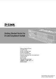
Package Contents<br />
Ver. 1.00(WW)<br />
FULL HD DAY & NIGHT<br />
User Manual and Software<br />
on CD-ROM<br />
Power Adapter AV/Power Cable<br />
CAT5 Ethernet Cable<br />
If any of the above items are missing, please contact your reseller.<br />
DCS-3715<br />
©2010 D-<strong>Link</strong> Corporation/D-<strong>Link</strong> Systems, Inc. All Rights Reserved.<br />
Screw Driver Alignment Sticker<br />
Quick Install Guide<br />
5
Product Overview<br />
D-<strong>Link</strong> DCS-6112 /6113 User Manual<br />
System Requirements<br />
Operating System: Microsoft Windows ® , 2000, XP, Vista, 7<br />
Memory : At least 256MB of memory (512MB recommended)<br />
Web Browser: Internet Explorer 6.x or higher<br />
VGA card resolution: SVGA or XGA (1024x768 or above)<br />
CPU: 1.7GHz or above (2.8GHz plus processor with 512MB memory and a 32MB video card is<br />
required for multiple camera viewing and recording in IP surveillance program)<br />
An available Ethernet connection<br />
6
Product Overview<br />
D-<strong>Link</strong> DCS-6112 /6113 User Manual<br />
Introduction<br />
D-<strong>Link</strong> DCS-6112/6113 are indoor fixed dome camera equipped with industry-leading high definition (Full HD) megapixel<br />
resolution and H.264 compression that enable high-quality video footage to be recorded. The DCS-6112/6113 connects to a network<br />
to provide high-quality live video over the Internet. The DCS-6113 is capable of capturing video in both dark and light environments<br />
thanks to its built-in IR LEDs and IR-cut removable (ICR) filter. The ICR filter allows the camera to capture crisp color images during the<br />
daytime and detailed grayscale images at night or in or low-light conditions.<br />
The built-in MicroSD card slot can be used as a local backup by storing important events on an easily retrievable MicroSD card.<br />
The included D-<strong>Link</strong> D-ViewCam is sophisticated software which allows users to manage up to 32 network cameras, set e-mail alert<br />
notifications, create recording schedules, and use motion detection to record directly to a hard drive. D-ViewCam also allows users to<br />
upload a floor plan to create a realistic layout of the premises where cameras are located, further simplifying the management process.<br />
7
Product Overview<br />
D-<strong>Link</strong> DCS-6112 /6113 User Manual<br />
Features<br />
Full HD Surveillance<br />
DCS-6112 /6113 provides Full HD industral standard 16:9 wide screen video for IP surveillance. To utilize the advantage of high<br />
resolution, the "viewing window" design can provide user a flexible settings to monitor multiple ROI(Region of Interest) by a single<br />
camera. And the "ePTZ" can also simulate wide area surveillance by digital zoom and pan, tilt control.<br />
Flexible Connectivity<br />
The DCS-6112 /6113 includes input and output ports for connectivity to external devices such as IR sensors, switches, and alarm<br />
relays. The DCS-6112 /6113 also incorporates Power over Ethernet (PoE), allowing it to be easily installed in a variety of locations<br />
without the need for supplemental power cabling.<br />
Advanced Web User Interface<br />
The DCS-6112 /6113 features D-<strong>Link</strong>’s latest-generation graphical user interface. This freshly-designed web interface features a<br />
clean, compact, and professional home screen which dramatically increases usability. Menu navigation is simplified thanks to a tree<br />
view which logically groups functions, helping users to quickly find what they need. Likewise, intuitive graphic icons reduce the amount<br />
text and clutter within the browser window. New users will appreciate the convenient contextual help which offers an easy way to find<br />
assistance with camera management tasks.<br />
3GPP Mobile Surveillance<br />
Support for 3GPP Mobile Surveillance allows users to view a live video feed from a 3GPP compatible Internet-ready mobile device.<br />
This extends monitoring capability, allowing users to check the camera’s video feed while on the go without a computer.<br />
Reliable 24-Hour Surveillance<br />
DCS-6113 is equipped infrared LED illuminators which provides a clear picture at night for dependable 24-hour surveillance.<br />
8
Product Overview<br />
D-<strong>Link</strong> DCS-6112 /6113 User Manual<br />
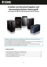
Hardware Overview<br />
Dome Cover<br />
Plastic housing<br />
9
Product Overview<br />
Light sensor<br />
Judges lighting conditions and<br />
switches from day mode to night mode<br />
accordingly (Control IR-LED and ICR<br />
on/off) (DCS-6113 only)<br />
3-Axis Mechanism<br />
Adjust the camera’s image to<br />
achieve the desired orientation<br />
MicroSD Card Slot<br />
Local MicroSD card for storing<br />
recorded images and video<br />
Reset<br />
Press and hold this button for 10<br />
seconds to reset the camera<br />
LED<br />
Audio I/O and DI/DO<br />
Power and<br />
1: Power + 12V network indicator<br />
2: Digital output<br />
3: Digital input<br />
4: Ground<br />
5: Audio input<br />
6: Ground of audio input<br />
7: Audio output<br />
8: Ground of audio output<br />
DC input / Video Output<br />
1: Ground of Video out<br />
2: Video output<br />
3: Ground of DC input<br />
4: DC 12V<br />
D-<strong>Link</strong> DCS-6112 /6113 User Manual<br />
NTSC/PAL Switch<br />
Switch for NTSC/PAL<br />
video format<br />
Infrared LEDs<br />
Used to illuminate the camera's field of view<br />
at night (DCS-6113 only)<br />
Lens<br />
Fixed focus lens<br />
Ethernet (PoE)<br />
RJ-45 connector for Ethernet which can also<br />
be used to power the camera using PoE<br />
Audio Input / Output<br />
Audio input/output connector for external<br />
speaker.<br />
Digital Input (DI) /Output (DO)<br />
DI/DO connectors provide a physical<br />
interface to send and receive digital signals<br />
to and from a variety of external devices<br />
DC Input<br />
Connects to the 12V DC power adapter<br />
to power the camera<br />
Video Output<br />
Video output connector for TV/Monitor<br />
10
Product Overview<br />
D-<strong>Link</strong> DCS-6112 /6113 User Manual<br />
Hardware Installation<br />
Mounting to a Ceiling or a Wall<br />
1.Locate an area on the ceiling or wall which is capable of supporting the weight of the camera.<br />
2.Attach the alignment sticker to the ceiling or wall.<br />
3.Drill two pilot holes where the holes of the alignment sticker are located.<br />
4.Insert the supplied plastic anchors into the drilled holes, and align the holes at the base of the camera with the plastic anchors.<br />
5.The camera can be mounted with the cable routed through the ceiling, wall or from the side.<br />
6.Insert the provided screws through the holes. Use a screwdriver to tighten and secure.<br />
11
Installation<br />
D-<strong>Link</strong> DCS-6112 /6113 User Manual<br />
Hardware Installation<br />
General Connection (without PoE)<br />
Connect the network camera to a switch or router via an Ethernet cable.<br />
Connect the supplied power cable from the camera to a power outlet.<br />
Connection with a PoE Switch<br />
If using a PoE switch, connect the network camera to the switch via an Ethernet cable, which will provide both power and data<br />
transmission over a single cable.<br />
12
Installation<br />
D-<strong>Link</strong> DCS-6112 /6113 User Manual<br />
Configuration with Wizard<br />
Insert the DCS-6112 /6113 CD into your computer's CD-ROM drive to begin<br />
the installation. If the Autorun function on your computer is disabled, or if<br />
the D-<strong>Link</strong> Launcher fails to start automatically, click Start > Run. Type D:\<br />
autorun.exe, where D: represents the drive letter of your CD-ROM drive.<br />
Click Setup Wizard to begin the installation.<br />
After clicking Setup Wizard, the following window will open.<br />
Click Next to continue.<br />
13
Installation<br />
Click Yes to accept the License Agreement.<br />
To start the installation process, click Next.<br />
Note: The installation may take several minutes to finish.<br />
D-<strong>Link</strong> DCS-6112 /6113 User Manual<br />
14
Installation<br />
Click Finish to complete the installation.<br />
Click on the D-<strong>Link</strong> Setup Wizard SE icon that was created in your Windows<br />
Start menu.<br />
Start > D-<strong>Link</strong> > Setup Wizard SE<br />
D-<strong>Link</strong> DCS-6112 /6113 User Manual<br />
15
Installation<br />
The Setup Wizard will appear and display the MAC address and IP address<br />
of your camera(s). If you have a DHCP server on your network, a valid IP<br />
Address will be displayed. If your network does not use a DHCP server, the<br />
network camera's default static IP 192.168.0.20 will be displayed.<br />
Click the Wizard button to continue.<br />
Enter the Admin ID and password. When logging in for the first time, the<br />
default Admin ID is admin with the password left blank.<br />
Click Next, to proceed to the next page.<br />
D-<strong>Link</strong> DCS-6112 /6113 User Manual<br />
16
Installation<br />
Select DHCP if your camera obtains an IP address automatically when it boots<br />
up. Select static IP if the camera will use the same IP address each time it is<br />
started.<br />
Click Next, to proceed to the next page.<br />
Take a moment to confirm your settings and click Restart.<br />
D-<strong>Link</strong> DCS-6112 /6113 User Manual<br />
17
Installation<br />
Click on the D-<strong>Link</strong> Setup Wizard SE icon that was created in your Windows<br />
Start menu.<br />
Start > D-<strong>Link</strong> > Setup Wizard SE<br />
D-<strong>Link</strong> DCS-6112 /6113 User Manual<br />
Web-based Configuration Utility<br />
This section explains how to configure your new D-<strong>Link</strong> Network Camera using the Web-based Configuration Utility.<br />
Select the camera and click the button labeled "<strong>Link</strong>" to access the web<br />
configuration.<br />
The Setup Wizard will automatically open your web browser to the IP address of<br />
the camera.<br />
Alternatively, you may manually open a browser and enter the IP address of the<br />
camera: 192.168.0.20<br />
18
Installation<br />
Enter admin as the default username and leave the password blank. Click OK to<br />
continue.<br />
This section shows your camera’s live video. You can select your video profile and<br />
view or operate the camera. For additional information about web configuration,<br />
please refer to the user manual included on the CD-ROM or the D-<strong>Link</strong> website.<br />
D-<strong>Link</strong> DCS-6112 /6113 User Manual<br />
19
Installation<br />
D-<strong>Link</strong> DCS-6112 /6113 User Manual<br />
Adjust the viewing angle<br />
Loosen the pan screw and turn the lens module left and right until the desired position is achieved; tighten the pan screw once<br />
completed. Loosen the tilt screws on both sides of the camera, and turn the lens module up and down until the desired position is<br />
achieved; tighten the tilt screws once completed.<br />
Loosen the image adjustment screw and turn the lens to adjust the network camera’s image until the desired orientation is achieved,<br />
tighten the image adjustment screw once completed.<br />
Rotate 350°<br />
Loosen Tighten<br />
Tilt 85°<br />
1.Align the inner side of the black cover with the notch on both<br />
sides of the lens, fix the black Cover.<br />
2.If you choose to the feed the cable through the ceiling or wall,<br />
arrange the cable neatly through the cable hole. If you choose to<br />
feed the cable from the side, remove plate A.<br />
3.Attach the dome cover to the camera as the direction shown<br />
below. With idiot-proof mechanism design, the dome cover<br />
cannot be attached if the angle does not fit.<br />
4.Finally, make sure all parts of the camera are securely installed.<br />
Attaching the Enclosure<br />
Pan 350°<br />
20
Installation<br />
D-<strong>Link</strong> DCS-6112 /6113 User Manual<br />
D-ViewCam Setup Wizard<br />
D-ViewCam software is included for the administrator to manage multiple<br />
D-<strong>Link</strong> IP cameras remotely. You may use the software to configure all<br />
the advanced settings for your cameras. D-ViewCam is a comprehensive<br />
management tool for IP surveillance.<br />
Insert the CD-ROM into the CD-ROM drive. Click "Install D-ViewCam<br />
Software" from menu, and select "D-ViewCam" to install the VMS software.<br />
Follow the Installation Wizard to install D-ViewCam.<br />
21
Installation<br />
Click Finish to complete the installation.<br />
To start D-ViewCam, select Start > All Programs > D-<strong>Link</strong> D-ViewCam ><br />
Main Console.<br />
For more detail operation of using D-ViewCam software, please refer to<br />
D-ViewCam Manual.<br />
D-<strong>Link</strong> DCS-6112 /6113 User Manual<br />
22
Configuration<br />
D-<strong>Link</strong> DCS-6112 /6113 User Manual<br />
Live Video<br />
When you connect to the camera's web interface you will see the following page. This is the Live Video page which will allow you<br />
to view the camera's video feed and control basic camera functions using the icons on the screen. Please refer to the tables on the<br />
following pages for detailed information about the icons on this screen.<br />
23
Configuration<br />
D-<strong>Link</strong> Logo<br />
Securicam Logo<br />
Client Settings<br />
Language<br />
Setup<br />
Digital Output<br />
Video Stream<br />
Global View<br />
D-<strong>Link</strong> DCS-6112 /6113 User Manual<br />
Click this logo to visit the D-<strong>Link</strong> website.<br />
The logos and website can be customized to fit your needs. For<br />
more information, please refer to User Customization on page 67.<br />
Setup the stream transmission mode and saving options on the<br />
local computer.<br />
Select this option to adjust the language settings.<br />
Click on the setup icon on the main page to enter the camera<br />
setting pages. Note that only Administrators can access the<br />
setup page. To simplify the setting procedure, two types of user<br />
interfaces are available: Advanced Setup for professional users<br />
and Basic Setup for entry-level users.<br />
Click this button to turn the digital output device on or off.<br />
This camera supports multiple streams (stream 1 ~ 4)<br />
simultaneously. You may select one for live viewing.<br />
Click on this item to display the Global View window. The Global<br />
View window contains a full view image (the largest frame size<br />
of the captured video) and a floating frame (the viewing region<br />
of the current video stream). The floating frame allows users to<br />
control the e-PTZ function (Electronic Pan/Tilt/Zoom). For more<br />
information about e-PTZ operation, please refer to PTZ Control.<br />
For more information about how to set up the viewing region of<br />
the current video stream, please refer to Video settings on page 31.<br />
24
Configuration<br />
ePT Direction<br />
Zoom<br />
Patrol Auto Pan<br />
Go Preset<br />
Speed Control<br />
D-<strong>Link</strong> DCS-6112 /6113 User Manual<br />
Home: Move the camera to the preset home position.<br />
Direction: Control the camera’s pan or tilt directions (up/down/left/<br />
right).<br />
Zoom in/out to magnify or shrink the digital image.<br />
Zoom in: Magnify image<br />
Zoom out: Diminish image<br />
Patrol: Patrol executes a pre-defined sequence of pan, tilt,<br />
zoom, and focus features Before selecting this, users must<br />
define at least two preset points.<br />
Auto Pan: Auto Pan automatically scans an area<br />
horizontally.<br />
Select from the preset drop-down list to quickly move the camera<br />
to the desired preset position.<br />
Control Pan/Tilt/Zoom speed<br />
Pan Speed Control<br />
Tilt Speed Control<br />
Zoom Speed Control<br />
Digital PTZ<br />
Control Panel<br />
25
Configuration<br />
Camera Control<br />
Snapshot<br />
Recording<br />
Recording Folder<br />
Digital Zoom<br />
Talk<br />
Microphone Level<br />
Microphone Mute<br />
Speaker Volumn<br />
Speaker Mute<br />
Full Screen<br />
Zoom ratio<br />
Help<br />
D-<strong>Link</strong> DCS-6112 /6113 User Manual<br />
Click this button to capture and save still images. The captured images will be displayed in a pop-up window. Right-click the image<br />
and choose Save Picture As to save it in JPEG (*.jpg) or BMP (*.bmp) format.<br />
Click this button to record video clips to your computer. When you exit the web browser, video recording stops accordingly.<br />
Specify a storage destination for the recorded video files.<br />
Click and uncheck “Disable digital zoom” to enable the zoom operation. The navigation screen indicates the part of the image being<br />
magnified. To control the zoom level, drag the slider bar. To move to a different area you want to magnify, drag the navigation screen.<br />
Talk/Stop Talk: Click this button to talk to people around the Network Camera if there is an external speaker connected to the<br />
camera and you have a microphone connected to your computer. Press the icon again to stop talking or disable this function.<br />
Microphone Level: When the mute function is not active, move the slider bar to adjust the level of the microphone (internal/external)<br />
that is connected to your network camera.<br />
Microphone Mute/Un-mute: Click to turn off the microphone (internal/external) that is connected to your network camera. Press again<br />
to turn the microphone back on.<br />
Speaker Volume - When the mute function is not active, move the slider bar to adjust the volume of the speakers that are connected<br />
to your network camera.<br />
Speaker Mute/Un-mute: Click to mute the external speaker that is connected to the network camera. Press again to un-mute the<br />
speaker.<br />
Click this button to switch to full screen mode. Press the “Esc” key to switch back to normal mode.<br />
Auto: The video zoom ratio will be changed automatically according to viewing window size.<br />
100%: Keep the video zoom ratio at 100%<br />
50%: Keep the video zoom ratio at 50%<br />
25%: Keep the video zoom ratio at 25%<br />
Click the Help button to learn the detailed information regarding camera setup and solve any problems you encounter.<br />
26
Configuration<br />
D-<strong>Link</strong> DCS-6112 /6113 User Manual<br />
Client Setup<br />
Clicking the Client Settings button will bring you to the following screen which<br />
allows you to configure the basic protocol options for you camera.<br />
H.264/MPEG4 Media Options<br />
Video and Audio can be viewed at the same time or seperately.<br />
H.264/MPEG4 Protocol Options<br />
For additional information about streaming options please see page 41.<br />
UDP Unicast: Stream to a single computer.<br />
UDP Multicast: Stream to multiple computers using multicast<br />
streaming.<br />
TCP: Provides higher quality video streaming than UDP and provides error<br />
correction. However, transmission speed will be reduced.<br />
HTTP: Offers the highest image and video quality. However, packet loss will<br />
diminish image quality when bandwidth becomes restricted. If the network is protected by a firewall and it opens only HTTP port (80),<br />
HTTP protocol must be selected. In this mode, audio is disabled and only video can be viewed. UDP connections will not be available<br />
to remote users if all four ports have not been forwarded (as shown on page 46). Only the HTTP port must be forwarded for remote<br />
users to make an HTTP connection (video only).<br />
MP4 Saving Options<br />
Folder: Select the folder where you would like the MP4 file saved on your desktop computer.<br />
File name prefix: Enter a file name prefix for the MP4 files.<br />
Add date and time suffix to file name: Select this checkbox if you would like the date and time to be added to the end of each<br />
filename.<br />
Local Streaming Buffer Time<br />
Enter the buffer time in milliseconds. The buffer will cause a slight delay between live activity and the video of the live stream but may<br />
increase the quality of video.<br />
27
Configuration<br />
Click the setup button to enter the setup screen.<br />
Click on the basic button to enter the setup screen.<br />
Please click the [+] next to each folder to view the options.<br />
Basic setup includes the following options:<br />
D-<strong>Link</strong> DCS-6112 /6113 User Manual<br />
Setup<br />
The DCS-6112 /6113 includes basic and advanced setup screens. Both screens include a tree view with multiple setup options. This<br />
manual includes detailed explanations for all advanced setup screens.<br />
Basic Setup<br />
System Overview<br />
Audio and Video<br />
- Video Settings, Audio Settings<br />
Network<br />
- IP Settings<br />
Event Management<br />
- Motion Detection, Tamper Detection<br />
PTZ Control<br />
- Digital PTZ<br />
System<br />
- User Settings, Device Settings, Time and Date, Maintenance<br />
28
Configuration<br />
Click the setup button to enter the setup screen.<br />
Click on the advanced button to enter the setup screen.<br />
Please click the [+] next to each folder to view the options.<br />
Advanced setup includes the following options:<br />
D-<strong>Link</strong> DCS-6112 /6113 User Manual<br />
Advanced Setup<br />
System Overview<br />
Audio and Video<br />
- Video Settings, Image Settings, Audio Settings, *Day and Night Settings<br />
* function for DCS-6113 only<br />
Network<br />
- IP Settings, Port & Access Name Settings, Dynamic DNS,<br />
HTTPS, Access List, Advanced Settings<br />
Event Management<br />
- Motion Detection, Tamper Detection, DI and DO, Event Settings<br />
Recording<br />
- Recording Settings, Local Storage<br />
PTZ Control<br />
- Digtal PTZ<br />
User Customization<br />
- Live Video Page Config, HTML Code Examples<br />
System<br />
- User Settings, Device Settings, Time and Date, Maintenance,<br />
Parameter List, Logs<br />
29
Configuration<br />
D-<strong>Link</strong> DCS-6112 /6113 User Manual<br />
System Overview<br />
The system overview page contains a summary of the camera's current<br />
settings. For more information about adjusting these settings, please consult<br />
the subsequent instructions found in this manual.<br />
30
Configuration<br />
Video Options<br />
Viewing Window: The camera supports multiple streams with frame size<br />
ranging from 176 x 144 to 1920 x 1080. Click Viewing Window to open the<br />
viewing region setting page. On this page, you can set the Region of Interest<br />
(ROI) and the Output Frame Size for stream 1~3. Please follow the steps<br />
below to set up a stream:<br />
1. Select a stream whose viewing region you would like to set.<br />
2. Select a Region of Interest from the drop-down list, the floating frame will<br />
resize accordingly. If you want to set up a customized viewing region, you<br />
can also resize and drag the floating frame to a desired position with your<br />
mouse.<br />
3. Choose a proper Output Frame Size from the drop-down list according to<br />
the size of your monitoring device.<br />
Note: All the items in the “Output Frame Size” should not be greater than the<br />
“Region of Interest “(current maximum resolution).<br />
The definition of multiple streams:<br />
D-<strong>Link</strong> DCS-6112 /6113 User Manual<br />
Video<br />
Video Settings<br />
This page allows you to set up 4 video streams to be displayed on a computer, mobile device, or storage system. Each stream has<br />
independent options for proper compression type, frame size, frame rate to optimize the bandwidth utilization and video quality.<br />
Stream 1-3: Users can define the "Region of Interest" (viewing region) and the<br />
"Output Frame Rate" (size of the live view window).<br />
Stream 4: This is global view stream which captures the full view of the video.<br />
Users can also define the "Output Frame Rate" (size of the live<br />
view window).<br />
31
Configuration<br />
Once finished with the setting in the Viewing Window, click Save to enable the<br />
settings and click Close to exit the window. The selected Output Frame Size<br />
will immediately be applied to the Frame size of video stream. You can then<br />
go back to the Live Video to test the new settings.<br />
Sensor Setting: Click Sensor Setting to open the Sensor Setting page. On<br />
this page, you can set the maximum exposure time, exposure level, and AGC<br />
(Auto Gain Control) setting. You can configure two sets of sensor setting: one<br />
for normal situations(Profile 1), the other for special situations, such as day/<br />
night/schedule mode(*Profile 2).<br />
* function for DCS-6113 only.<br />
Exposure<br />
• Maximum Exposure Time: Select a proper maximum exposure time<br />
according to the light source of the surroundings. Shorter exposure times<br />
result in less light reaching the sensor. The exposure times are selectable<br />
for the following durations: 1/5, 1/15, 1/30, 1/60,1/120,1/240,1/480 second.<br />
• Exposure level: You can manually set the Exposure level which ranges<br />
from 1 to 8 (dark to bright).<br />
• Max. Gain (Auto Gain Control): You can manually set the AGC level (2X<br />
4X, or 8X). The higher the value, the brighter the image will be.<br />
• Enable BLC (Back Light Compensation): Enable this option when the<br />
object is too dark or too bright to recognize. It allows the camera to adjust<br />
to the best light conditions in any environment and automatically give the<br />
necessary light compensation.<br />
You may click Preview to fine-tune the image, or click Restore to recall the<br />
original setting without incorporating the changes. When completed with<br />
the setting on this page, click Save to enable the setting and click Close to<br />
exit the page. If you want to configure another sensor setting for day/night/<br />
schedule mode, please click Profile 2 and follow the steps below to setup:<br />
1. Click Enable this profile.<br />
2. Select the applied mode: Day mode, Night mode, or schedule mode.<br />
Please manually enter a range of time if you choose Schedule mode.<br />
3. Configure Exposure setting in the second column.<br />
4. Click Save to enable the setting and click Close to exit the page.<br />
D-<strong>Link</strong> DCS-6112 /6113 User Manual<br />
32
Configuration<br />
Video Quality Setting for Stream 1~4<br />
Compression Type: The compression level affects the amount of bandwidth<br />
and storage required. Lower compression uses more bandwidth and storage<br />
but delivers better image quality. Of the three options, H.264 consumes much<br />
less network bandwidth compared to MPEG4 and JPEG.<br />
Frame Size: Select proper frame size for different viewing devices, bigger<br />
frame size requires more bandwidth and storage usage. For smaller<br />
viewers, such as mobile phones, a smaller frame size and lower frame rate<br />
is recommended. There are 7 options you can select: 176x144, 384x216,<br />
640x360, 1280x720, 1360x768, 1600x904 and 1920x1080, if there is no<br />
viewing window applied. (176x144 for mobile phone, 1280x720 and 1920 x<br />
1080 for HD display).<br />
Frame Rate: This option affects the smoothness of the video. Select higher<br />
frame rate for smoother video quality but it requires more storage usage. 10<br />
options for selection: customize, 1, 3, 5, 8, 10, 15, 20, 25, 30 fps (30 fps is<br />
recommended real-time video on a computer monitor. 5 fps is ideal for mobile<br />
viewers.)<br />
Intra Frame Period: Determines the frequency and I frame is planted. The<br />
shorter the duration, the more likely you will get better video quality, but at the<br />
cost of higher network bandwidth consumption. Select the intra frame period<br />
from the following durations: 1/4 second, 1/2 second, 1 second, 2 seconds, 3<br />
seconds and 4 seconds.<br />
Video Quality: This setting limits the maximum refresh frame rate.<br />
• Constant bit rate: To set a fixed bandwidth regardless of the video<br />
quality, select Constant bit rate and the desired bandwidth from 20 Kbps to<br />
8 Mbps. You can also select Customize and manually enter a value.<br />
• Fixed quality: To optimize the bandwidth utilization and video quality. The<br />
video quality can be adjusted to the following setting: Medium, Standard,<br />
Good, Detailed and Excellent. You can also select Customize and<br />
manually enter a value.<br />
D-<strong>Link</strong> DCS-6112 /6113 User Manual<br />
33
Configuration<br />
D-<strong>Link</strong> DCS-6112 /6113 User Manual<br />
Image Settings<br />
This page allows you to tune the white balance, brightness, saturation,<br />
contrast, and sharpness settings for the video.<br />
Color: Select either a Color or B/W (black and white, monochrome) video<br />
display.<br />
Power Line Frequency: Select either 50 or 60 Hz depending on your region.<br />
Video Orientation: Flip will vertically rotate the video. Mirror will horizontally<br />
rotate the video. You may select both options if camera is being installed<br />
upside down.<br />
White Balance: This adjusts the relative amount of red, green and blue<br />
primary colors in the image so that the neutral colors are reproduced correctly.<br />
• Auto: The camera automatically adjusts the color temperature of the light<br />
in response to different light sources. The white balance setting defaults to<br />
Auto and works well in most situations.<br />
• Fixed: Follow the steps below to manually set the white balance to<br />
compensate for the ambient lighting conditions<br />
1. Set the White balance to Auto and click Save.<br />
2. Place a sheet of white paper in front of the lens, then allow the camera to<br />
adjust the color temperature automatically.<br />
3. Select Fixed to confirm the setting while the white balance is being<br />
measured.<br />
4. Click Save to enable the new setting.<br />
34
Configuration<br />
Brightness: Adjust the image brightness level, which ranges from -5 to +5<br />
Saturation: Adjust the image saturation level, which ranges from -5 to +5<br />
Contrast: Adjust the image contrast level, which ranges from -5 to +5<br />
Sharpness: Adjust the image sharpness level, which ranges from -3 to +3<br />
Overlay Title and Time Stamp on Video: Select this option to place the<br />
video title and time on the video streams. (When the frame size is set to 176 x<br />
144 only the time will be stamped on the video streams.)<br />
Note:<br />
• The "Sensor Settings" and "Image Settings" share the same *Profile 2<br />
settings.<br />
* function for DCS-6113 only.<br />
Privacy Mask: In this page, you can block out certain sensitive zones for<br />
privacy concerns. To set up a Privacy Mask Window, follow the steps given<br />
below:<br />
1. Click New to add a window.<br />
2. The height and width of the window can be resized and drag-dropped the<br />
window.<br />
3. Enter a descriptive Window Name and click Save to apply changes.<br />
4. Select Enable privacy mask to facilitate this function.<br />
None:<br />
• Up to 5 privacy mask windows can be set up on the same screen.<br />
• If you want to delete the privacy mask window, please click the ‘x’ at the<br />
upper right-hand corner of the window.<br />
D-<strong>Link</strong> DCS-6112 /6113 User Manual<br />
35
Configuration<br />
D-<strong>Link</strong> DCS-6112 /6113 User Manual<br />
Audio Settings<br />
Mute: Select to mute audio.<br />
Note:<br />
• If the switch on the Control board is switched off (disabled audio) then this<br />
option will be disabled.<br />
Select and set an internal microphone input gain from the drop-down list.<br />
External microphone input: Set the microphone input gain at either 0dB or<br />
20dB.<br />
Note: The higher the decibel number, the louder the sound.<br />
Audio type: Advanced Audio Coding (AAC) is a wide band audio coding<br />
algorithm that exploits two primary coding strategies to dramatically reduce<br />
the amount of data needed to convey high-quality digital audio. Select a<br />
higher bit rate number for better audio quality.<br />
AAC bit rate: Select an AAC bit rate from the drop-down list. Higher bit rate<br />
means higher audio quality but it takes more network bandwidth to transmit.<br />
GSM-AMR: A standard adapted audio codec by the 3GPP video (3rd<br />
Generation Partnership Project). It is an Adaptive Multi Rate-Narrow Band<br />
(AMRNB) speech codec. Select a higher bit rate number for better audio<br />
quality.<br />
GSM-AMR bit rate: Select the GSM-AMR bit rate from the drop-down<br />
list. Higher bit rate means higher audio quality but it takes more network<br />
bandwidth to transmit.<br />
36
Configuration<br />
D-<strong>Link</strong> DCS-6112 /6113 User Manual<br />
*Day and Night Settings<br />
* Day & night funciton for DCS-6113 only.<br />
Switch to B/W in Night Mode: Select to automatically enable the camera to<br />
switch to B/W night mode.<br />
IR Cut Filter: The IR-Cut Removable (ICR) filter mechanically switches<br />
between two different sensor filters. It provides the best light conditions both<br />
during the day and night. The following options are:<br />
• Auto Mode: The camera automatically switches between day and night<br />
mode by judging the level of ambient light. This mode is accessible only<br />
when the exposure mode is set to Auto.<br />
• Day Mode: In this mode the camera switches on the IR cut filter at all<br />
times, which will block the infrared light from reaching the sensor so that<br />
the colors are not distorted.<br />
• Night Mode: The camera switches off the IR cut filter to allow the infrared<br />
light to pass through. This helps the camera to see more clearly in low light<br />
conditions.<br />
• Synchronize with Digital Input: The camera automatically removes the<br />
IR cut filter when DI triggers.<br />
• Schedule Mode: The camera switches between day and night mode<br />
based on a specific schedule. Ensure to enter the starting and ending time<br />
for the day mode. Note that the time format is [hh:mm] and is expressed<br />
in 24-hour clock time. By default, the starting time and ending time of day<br />
mode are set to 07:00 and 18:00.<br />
Light Sensor Sensitivity: Select Low, Normal, or High sensitivity for the light<br />
sensor.<br />
Disable IR LED: Select this box to disable the IR LED. The IR LED<br />
automatically switches on at night. By default the LED automatically switches<br />
on at night.<br />
37
Configuration<br />
D-<strong>Link</strong> DCS-6112 /6113 User Manual<br />
Network<br />
IPv4<br />
LAN: Select this option when the camera is deployed on a local area network<br />
(LAN) and is intended to be accessed by local computers. The default setting<br />
for the Network Type is LAN. Remember to click Save when you complete the<br />
Network setting.<br />
• Get IP address automatically (DHCP): Select this connection if you<br />
have a DHCP server running on your network and would like a dynamic IP<br />
address to be assigned to the camera automatically.<br />
• Use fixed IP address: You may enter a static or fixed IP address for your<br />
camera.<br />
IP Address: Enter an IP address.<br />
IP Settings<br />
Subnet Mask: The default value is “255.255.255.0.” This helps to determine if<br />
the designated IP address is on the same subnet.<br />
Default Router: This is the gateway used to forward frames to destinations in<br />
a different subnet. (Invalid router setting will cause the transmission to fail if its<br />
destination is in a different subnet).<br />
Primary DNS: The Primary Domain Name Server (DNS) that translates<br />
hostname into IP address.<br />
Secondary DNS: Secondary Domain Name Server (DNS) that backups the<br />
Primary DNS.<br />
Primary WINS Server: The primary WINS server that maintains the database<br />
of computer name and IP address.<br />
38
Configuration<br />
Secondary WINS Server: The secondary WINS server that maintains the<br />
database of computer name and IP address.<br />
• Enable UPnP Presentation: Select this option to enable UPnP<br />
presentation for the camera so that whenever a camera is presented to the<br />
LAN, shortcuts of connected cameras will be listed in My Network Places.<br />
You can click the shortcut to link to the web browser. Currently, UPnP is<br />
supported by Windows XP or later. Note that to utilize this feature, please<br />
make sure the UPnP component is installed on your computer.<br />
• Enable UPnP Port Forwarding: To access the camera from the<br />
Internet, select this option to allow the camera to open ports on the router<br />
automatically so that video streams can be sent out from a LAN. To utilize<br />
this feature, make sure that your router supports UPnP and it is activated.<br />
How does UPnP work?<br />
UPnP networking technology provides automatic IP configuration and dynamic<br />
discovery of devices added to a network. Services and capabilities offered<br />
by networked devices, such as printing and file sharing, are available among<br />
each other without bothersome network configuration. In the case of Network<br />
Cameras, you will see Network Camera shortcuts at My Network Places.<br />
PPPoE: Select this option to configure the camera to make it accessible<br />
from anywhere with an Internet connection. Note that to utilize this feature, it<br />
requires an account provided by your ISP.<br />
Follow the steps below to acquire the camera’s public IP address.<br />
1. Set up the camera on the LAN<br />
2. Go to Live View > Setup > Event management > Event settings ><br />
Server Settings (please refer to Server Settings to add a new e-mail or<br />
FTP server)<br />
3. Go to Setup > Event management > Event settings > Media Settings<br />
(please refer to Media Settings). Select System log so that you will receive<br />
the system log in TXT file format which contains the camera’s public IP<br />
address in your e-mail or on the FTP server.<br />
D-<strong>Link</strong> DCS-6112 /6113 User Manual<br />
39
Configuration<br />
4. Go to Setup > Network > IP settings. Select PPPoE and enter the user<br />
name and password provided by your ISP. Click Save to enable the<br />
setting.<br />
5. The camera will reboot.<br />
6. Disconnect the power to the camera. Remove it from the LAN environment.<br />
IPv6<br />
Enable IPv6: Select this option and click Save to enable IPv6 setting. Please<br />
note that this only works if your network environment and hardware equipment<br />
support IPv6. The browser should be Microsoft ® Internet Explorer 6.5, Mozilla<br />
Firefox 3.0 or above.<br />
When IPv6 is enabled, by default, the camera will listen to router<br />
advertisements and be assigned a link-local IPv6 address accordingly.<br />
IPv6 Information: Click this button to obtain the IPv6 information. If your<br />
IPv6 setting are successful, the IPv6 address list will be listed in the pop-up<br />
window.<br />
Please follow the steps below to link to an IPv6 address:<br />
1. Open your web browser.<br />
2. Enter the link-global or link-local IPv6 address in the address bar of your<br />
web browser.<br />
3. Press Enter on the keyboard or click Refresh button to refresh the<br />
webpage.<br />
Manually Setup the IP Address: Select this option to manually configure<br />
IPv6 setting if your network environment does not have DHCPv6 server and<br />
advertisements-enabled routers.<br />
D-<strong>Link</strong> DCS-6112 /6113 User Manual<br />
40
Configuration<br />
D-<strong>Link</strong> DCS-6112 /6113 User Manual<br />
Port and Access Name Settings<br />
HTTPS<br />
By default, the HTTPS port is set to 443. It can also be assigned to another<br />
port number between 1025 and 65535.<br />
Two way audio<br />
The two way audio port is set to 5060 by default. It can also be assigned to<br />
another port number between 1025 and 65535.<br />
This Network Camera supports two way audio communication so that<br />
operators can transmit and receive audio simultaneously.<br />
By using the external microphone and an external speaker, users can<br />
communicate with people present around the Network Camera.<br />
Note: JPEG only transmits a series of JPEG images to the client. In order to<br />
utilize this audio feature, make sure the video<br />
mode is set to H.264 or MPEG-4 and the media option in "Client Settings" is<br />
set to Video and Audio.<br />
FTP<br />
The FTP server allows the user to save recorded video clips. You can utilize<br />
D-<strong>Link</strong>'s IP Cam Wizard to upgrade the firmware via FTP server. By default,<br />
the FTP port is set to 21. It also can be assigned to another port number<br />
between 1025 and 65535.<br />
HTTP port/Secondary HTTP port<br />
They can also be assigned to another port number between 1025 and<br />
65535. To access the Network Camera on the LAN, both the HTTP port<br />
and secondary HTTP port can be used to access the Network Camera For<br />
example, when the HTTP port is set to 80 and the secondary HTTP port is set<br />
to 8080. You can login camera as example link as below:<br />
Http://192.168.0.20 or<br />
Http://192.168.0.20:8080<br />
41
Configuration<br />
Authentication: Depending on your network security requirements, the<br />
Authentication: Depending on your network security requirements, the<br />
Network Camera provides three types of security settings for streaming via<br />
HTTP protocol: disable, basic, and digest. If basic authentication is selected,<br />
the password is sent in plain text format, but there can be potential risks<br />
of it being intercepted. If digest authentication is selected, user credentials<br />
are encrypted using MD5 algorithm, thus providing better protection against<br />
unauthorized access.<br />
Access name for stream 1 ~ 5: This Network Camera supports multiple<br />
streams simultaneously. The access name is used to differentiate the<br />
streaming source. When using Mozilla Firefox or Netscape to access the<br />
Network Camera and the video mode is set to JPEG, users will receive video<br />
comprised of continuous JPEG images This technology, known as “server<br />
push”, allows the Network Camera to feed live pictures to Mozilla Firefox and<br />
Netscape. And use the following HTTP URL command to request transmission<br />
of the streaming data.<br />
For example: http://:/<br />
For example, when the Access name for stream 3 is set to video3.mjpg:<br />
1. Launch Mozilla Firefox or Netscape.<br />
2. Type the above URL command in the address bar. Press Enter.<br />
3. The JPEG images will be displayed in your web browser.<br />
NOTE:<br />
1. Microsoft ® Internet Explorer does not support server push technology;<br />
therefore, using http://:/ will fail to access the Network Camera.<br />
2. Stream 5 is a special stream which users can only use URL commands to<br />
request the stream 5.<br />
D-<strong>Link</strong> DCS-6112 /6113 User Manual<br />
42
Configuration<br />
RTSP<br />
Authentication: Depending on your network security requirements, the Network Camera provides three types of security settings for<br />
streaming via RTSP protocol: disable, basic, and digest. If basic authentication is selected, the password is sent in plain text format,<br />
but there can be potential risks of it being intercepted. If digest authentication is selected, user credentials are encrypted using MD5<br />
algorithm, thus providing better protection against unauthorized access.<br />
Access name for stream 1 ~ 5: This Network Camera supports multiple streams simultaneously. The access name is used to<br />
differentiate the streaming source. If you want to use an RTSP player to access the Network Camera, you have to set the video mode<br />
to H.264 / MPEG-4 and use the following RTSP URL command to request transmission of the streaming data.<br />
RTSP port /<br />
RTP port for video, audio/<br />
RTCP port for video, audio<br />
� RTSP (Real-Time Streaming Protocol) controls the delivery of streaming media. By default, the port number is set to 554.<br />
� The RTP (Real-time Transport Protocol) is used to deliver video and audio data to the clients. By default, the RTP port for video is<br />
set to 5556 and the RTP port for audio is set to 5558.<br />
� The RTCP (Real-time Transport Control Protocol) allows the Network Camera to transmit the data by monitoring the Internet traffic<br />
volume. By default, the RTCP port for video is set to 5557 and the RTCP port for audio is set to 5559.<br />
The ports can be changed to values between 1025 and 65535. The RTP port must be an even number and the RTCP port is the RTP<br />
port number plus one, and thus is always an odd number. When the RTP port changes, the RTCP port will change accordingly.<br />
Multicast:Click the items to display the detailed configuration information. Select the Always multicast option to enable multicast for<br />
stream 1 ~ 4.<br />
Unicast video transmission delivers a stream through point-to-point transmission; multicast, on the other hand, sends a stream to the<br />
multicast group address and allows multiple clients to acquire the stream at the same time by requesting a copy from the multicast<br />
group address. Therefore, enabling multicast can effectively save network bandwidth.<br />
Multicast RTP video, audio port/<br />
Multicast RTCP video, audio port<br />
The ports can be changed to values between 1025 and 65535. The multicast RTP port must be an even number and the multicast<br />
RTCP port number is the multicast RTP port number plus one, and thus is always odd. When the multicast RTP port changes, the<br />
multicast RTCP port will change accordingly.<br />
Multicast TTL [1~255]: The multicast TTL (Time To Live) is the value that tells the router the range a packet can be forwarded.<br />
D-<strong>Link</strong> DCS-6112 /6113 User Manual<br />
43
Configuration<br />
D-<strong>Link</strong> DCS-6112 /6113 User Manual<br />
Dynamic DNS<br />
This section explains how to configure the dynamic domain name service<br />
for the camera. DDNS is a service that allows your camera, especially when<br />
assigned with a dynamic IP address, to have a fixed host and domain name.<br />
Enable DDNS: Select this option to enable the DDNS setting.<br />
Server Name: Select a DDNS server name from the provider drop-down<br />
list. With a Dynamic DNS account, the camera automatically updates your IP<br />
address. To enable DDNS, enter your host information. Click Next to continue.<br />
Host Name: Enter the host name of the DDNS server.<br />
Username: Enter your username or e-mail used to connect to the DDNS<br />
Password: Enter your password used to connect to the DDNS server.<br />
Status: Indicate the connection status, automatically determined by the<br />
system.<br />
44
Configuration<br />
D-<strong>Link</strong> DCS-6112 /6113 User Manual<br />
HTTPS<br />
This section explains how to enable authentication and encrypted<br />
communication over SSL (Secure Socket Layer). It helps protect streaming<br />
data transmission over the Internet on higher security level.<br />
Enable HTTPS<br />
Select this item to enable HTTPS communication, then select a connection<br />
option: "HTTP & HTTPS" or "HTTPS only". Note that you have to create and<br />
install a certificate first in the second column before clicking the Save button.<br />
Create and Install Certificate Method<br />
Before using HTTPS for communication with the camera, a certificate must be<br />
created first.<br />
There are three ways to create and install a certificate:<br />
Create Self-signed Certificate Automatically<br />
1. Select this option.<br />
2. In the first column, select Enable HTTPS secure connection, then select<br />
a connection option: “HTTP & HTTPS” or “HTTPS only”.<br />
3. Click Save to generate a certificate.<br />
4. The Certificate Information will automatically be displayed in the third<br />
column. You can click Property to view detailed information about the<br />
certificate.<br />
5. Click Live Video to return to the main page. Change the address from<br />
“http://” to “https://“ in the address bar and press Enter. Some Security<br />
Alert dialogs will pop up. Click OK or Yes to enable HTTPS.<br />
Create Self-signed Certificate Manually<br />
1. Click Create to open the Create Certificate page, then click Save to<br />
generate the certificate.<br />
2. The Certificate Information will automatically be displayed in the third<br />
column as shown below. You can click Property to see detailed<br />
information about the certificate.<br />
45
Configuration<br />
Create Certificate Request and Install<br />
Select this option to create a certificate from a certificate authority.<br />
1. Click Create to open the Create Certificate page, then click Save to<br />
generate the certificate.<br />
2. If you see the information bar, click OK and click on the Information bar at<br />
the top of the page to allow pop-up.<br />
3. The pop-up window shows an example of a certificate request.<br />
4. Look for a trusted certificate authority that issues digital certificates. Enroll<br />
the camera.<br />
Wait for the certificate authority to issue a SSL certificate. Click Browse... to<br />
search for the issued certificate, then click Upload in the second column.<br />
How do I cancel the HTTPS setting?<br />
1. Deselect Enable HTTPS secure connection in the first column and click<br />
Save. A warning dialog will pop up.<br />
2. Click OK to disable HTTPS.<br />
3. The webpage will redirect to a non-HTTPS page automatically.<br />
If you want to create and install other certificates, please remove the existing<br />
one. To remove the signed certificate, deselect Enable HTTPS secure<br />
connection in the first column and click Save. Then click Remove to erase the<br />
certificate.<br />
D-<strong>Link</strong> DCS-6112 /6113 User Manual<br />
46
Configuration<br />
D-<strong>Link</strong> DCS-6112 /6113 User Manual<br />
Access List<br />
This section explains how to control access permissions by verifying the<br />
connecting client PC’s IP address.<br />
General Settings<br />
Maximum number of concurrent streaming connection(s) limited to:<br />
Simultaneous live viewing for 1~10 clients (including stream 1 ~ stream 5).<br />
The default value is 10. If you modify the value and click Save, all current<br />
connections will be disconnected and automatically attempt to re-link (I.E.<br />
Explorer or Quick Time Player).<br />
View Information: Click this button to display the connection status window<br />
showing a list of the current connections.<br />
• IP address: Current connections to the camera.<br />
• Elapsed time: How much time the client has been at the webpage.<br />
• User ID: If the administrator has set a password for the webpage, the<br />
clients have to enter a user name and password to access the live video.<br />
The user name will be displayed in the User ID column. If the administrator<br />
allows client to link to the webpage without a user name and password, the<br />
User ID column will be empty.<br />
There are some situations which allow clients access to the live video without<br />
a user name and password:<br />
1. The administrator did not set up a user password. For more information<br />
about how to set up a user password and manage user accounts, please<br />
refer to User settings.<br />
2. The administrator has set up a user password, but set RTSP<br />
Authentication to “disable“. For more information about RTSP<br />
Authentication, please refer to RTSP Streaming.<br />
47
Configuration<br />
• Refresh: Click this button to refresh all current connections.<br />
• Add to deny list: You can select entries from the Connection Status list and add them to the Deny<br />
List to deny access. Please note that the selected connections will only be disconnected temporarily<br />
and will automatically try to re-link again (IE Explore or Quick Time Player). If you want to enable the<br />
denied list, please select Enable access list filtering and click Save in the first column.<br />
Disconnect: If you want to break off the current connections, please select them and click this button.<br />
Please note that those selected connections will only be disconnected temporarily and will automatically<br />
try to re-link again (IE Explore or Quick Time Player).<br />
Enable Access List Filtering: Select this item and click Save if you want to enable the access list<br />
filtering function.<br />
Filter Type<br />
Select Allow or Deny as the filter type. If you choose Allow Type, only those clients whose IP addresses<br />
are on the Access List below can access the camera, and the others cannot access. On the contrary,<br />
if you choose Deny Type, those clients whose IP addresses are on the Access List below will not be<br />
allowed to access the camera, and the others can access.<br />
Filter<br />
Then you can add a rule to the following Access List. Please note that the IPv6 access list column will<br />
not be displayed unless you enable IPv6 on the Network page. For more information about IPv6 Setting,<br />
please refer to Enable IPv6 for detailed information.<br />
There are three types of rules:<br />
Single: This rule allows the user to add an IP address to the Allowed/Denied list.<br />
Network: This rule allows the user to assign a network address and corresponding subnet mask to the<br />
Allow/Deny List.<br />
Range: This rule allows the user to assign a range of IP addresses to the Allow/Deny List (This rule is<br />
only applied to IPv4).<br />
Administrator IP address<br />
Always allow the IP address to access this device: You can select this item and add the Administrator’s IP<br />
address in this field to make sure the Administrator can always connect to the device.<br />
D-<strong>Link</strong> DCS-6112 /6113 User Manual<br />
48
Configuration<br />
D-<strong>Link</strong> DCS-6112 /6113 User Manual<br />
Advanced Settings<br />
SNMP configuration<br />
This section explains how to use the SNMP on the network camera. The<br />
Simple Network Management Protocol is an application layer protocol that<br />
facilitates the exchange of management information between network devices.<br />
It helps network administrators to remotely manage network devices and find,<br />
solve network problems with ease.<br />
The SNMP consists of the following three key components:<br />
1. Manager: Network-Management Station (NMS), a server which executes<br />
applications that monitor and control managed devices.<br />
2. Agent: A network-management software module on a managed device<br />
which transfers the status of managed devices to the NMS.<br />
3. Managed device: A network node on a managed network. For example:<br />
routers, switches, bridges, hubs, computer hosts, printers, IP telephones,<br />
network cameras, web server, and database.<br />
Before configuring SNMP setting on this page, please enable your NMS first.<br />
Enable SNMPv1, SNMPv2c: Select this option and enter the names of Read/<br />
Write community and Read Only community according to your NMS setting.<br />
Enable SNMPv3: This option contains cryptographic security, a higher security<br />
level which allows you to set the Authentication password and the Encryption<br />
password.<br />
• Security name: According to your NMS setting, choose Read/Write or<br />
Read Only and enter the community name.<br />
• Authentication type: Select MD5 or SHA as the authentication method.<br />
• Authentication password: Enter the password for authentication (at least<br />
8 characters).<br />
• Encryption password: Enter a password for encryption (at least 8<br />
characters).<br />
49
Configuration<br />
IEEE 802.1x<br />
Enable this function if your network environment uses IEEE 802.1x which<br />
is a port-based network access control. The network devices, intermediary<br />
switch/access point/hub, and RADIUS server must support and enable 802.1x<br />
setting.<br />
The 802.1x standard is designed to enhance the security of local area<br />
networks, which provides authentication to network devices (clients)<br />
attached to a network port (wired or wireless). If all certificates between<br />
client and server are verified, a point-to-point connection will be enabled. If<br />
authentication fails, access on that port will be prohibited. 802.1x utilizes an<br />
existing protocol, the Extensible Authentication Protocol (EAP), to facilitate<br />
communication.<br />
Please follow the steps below to enable 802.1x setting:<br />
1. Before connecting the camera to the protected network with 802.1x,<br />
please apply a digital certificate from a Certificate Authority (ie. MIS of your<br />
company) which can be validated by a RADIUS server.<br />
2. Connect the camera to a PC or notebook outside of the protected LAN.<br />
Open the configuration page of the camera as shown below. Select EAP-<br />
PEAP or EAP-TLS as the EAP method. In the following blanks, enter your<br />
ID and password issued by the CA, then upload related certificate(s).<br />
3. When all setting are complete, move the camera to the protected LAN by<br />
connecting it to an 802.1x enabled switch. The devices will then start the<br />
authentication automatically.<br />
QoS (Quality of Service)<br />
Quality of Service refers to a resource reservation control mechanism, which<br />
guarantees a certain quality to different services on the network. Quality<br />
of service guarantees are important if the network capacity is insufficient,<br />
especially for real-time streaming multimedia applications. Quality can be<br />
defined as, for instance, a maintained level of bit rate, low latency, no packet<br />
dropping, etc.<br />
D-<strong>Link</strong> DCS-6112 /6113 User Manual<br />
50
Configuration<br />
The following are the main benefits of a QoS-aware network:<br />
The ability to prioritize traffic and guarantee a certain level of performance to<br />
the data flow.<br />
The ability to control the amount of bandwidth each application may use, and<br />
thus provide higher reliability and stability on the network.<br />
Requirements for QoS:<br />
To utilize QoS in a network environment, the following requirements must be<br />
met:<br />
• All network switches and routers in the network must include support for<br />
QoS.<br />
• The network video devices used in the network must be QoS-enabled.<br />
CoS<br />
IEEE802.1p defines a QoS model at OSI Layer 2 (Data <strong>Link</strong> Layer), which is<br />
called CoS, Class of Service. It adds a 3-bit value to the VLAN MAC header,<br />
which indicates prioritization from 0~7 (Eight different classes of service are<br />
available). The priority is set up on the network switches, which then use<br />
different queuing disciplines to forward the packets.<br />
Please follow the steps below to enable CoS settings:<br />
1. Click Enable CoS<br />
2. Enter the VLAN ID of your switch (0~4095)<br />
3. Choose the priority for each application (0~7).<br />
Note:<br />
• The VLAN Switch (802.1p) is required. The web browsing may fail if the<br />
CoS setting is incorrect.<br />
• Class of Service technologies do not guarantee a level of service in terms<br />
of bandwidth and delivery time. They only offer a "best-effort." Users<br />
can think of CoS as "coarsely-grained" traffic control and QoS as "finelygrained"<br />
traffic control.<br />
• Though CoS is simple to manage, it lacks scalability and does not offer<br />
end-to-end guarantees since it is based on L2 protocol.<br />
D-<strong>Link</strong> DCS-6112 /6113 User Manual<br />
51
Configuration<br />
QoS/DSCP<br />
DSCP-ECN defines QoS at Layer 3 (Network Layer). The Differentiated Services (DiffServ) model is based on packet marking and<br />
router queuing disciplines. The marking is done by adding a field to the IP header, called the DSCP (Differentiated Services Code<br />
Point). This is a 6-bit field that provides 64 different class IDs. It gives an indication of how a given packet is to be forwarded, known<br />
as the Per Hop Behavior (PHB). The PHB describes a particular service level in terms of bandwidth, queuing theory, and dropping<br />
(discarding the packet) decisions. Routers at each network node classify packets according to their DSCP value and give them a<br />
particular forwarding treatment. For example, how much bandwidth should be reserved.<br />
Quality of Service refers to a resource reservation control mechanism, which guarantees a certain quality to different services on the<br />
network. Quality of service guarantees are important if the network capacity is insufficient, especially for real-time streaming multimedia<br />
applications. Quality can be defined as, for instance, a maintained level of bit rate, low latency, no packet dropping, etc.<br />
D-<strong>Link</strong> DCS-6112 /6113 User Manual<br />
52
Configuration<br />
Motion can be detected by measuring change in speed or vector of an object or<br />
objects in the field of view.<br />
Enable Motion Detection: Select this option to turn on the motion detection<br />
feature.<br />
Window Name: Create your own name for the monitored area/ window. It will<br />
show at the top of the motion window.<br />
Sensitivity: Set the measurable difference between two sequential images that<br />
would indicate motion.<br />
Percentage: Set the amount of motion in the window being monitored that is<br />
required to trigger a motion detected alert. If this is set to 100%, this means that<br />
motion must be detected within the whole window to trigger a snapshot.<br />
Note: Setting a higher sensitivity and a lower percentage will make motion easier<br />
to be detected.<br />
New: Click to add a new window. A maximum of three motion windows can be<br />
opened simultaneously. Use your mouse to drag the window frame to resize or<br />
the title bar to move. Clicking on the ‘x’ at the upper right corner of the window will<br />
close the window.<br />
Save: Save the configured settings.<br />
D-<strong>Link</strong> DCS-6112 /6113 User Manual<br />
Event Management<br />
Motion Detection<br />
To enable motion detection, follow the steps below:<br />
1. Click New to add a new motion detection window.<br />
2. Enter a name in the Window Name field.<br />
3. Define the sensitivity to moving objects and the space ratio of all alerted pixels<br />
by moving the Sensitivity and Percentage slide bar.<br />
4. Click Save to apply the changes.<br />
5. Select Enable motion detection to activate motion detection.<br />
Profile:<br />
You can configure two sets of sensor setting:<br />
one for normal situations(Profile1), the other for<br />
special situations(Profile2), such as day/night/<br />
schedule mode.<br />
53
Configuration<br />
D-<strong>Link</strong> DCS-6112 /6113 User Manual<br />
Tamper Detection<br />
With tamper detection, the camera is capable of detecting incidents such as<br />
redirection, blocking or de-focusing, or even spray paint.<br />
To enable tamper detection, follow the steps given below:<br />
1. Select Enable camera tampering detection.<br />
2. Enter the tamper trigger duration (10 sec. ~ 10 min.). The tamper alarm<br />
will be triggered only when the tampering factor (the difference between<br />
current frame and pre-saved background) exceeds the trigger threshold.<br />
Set up the event source as Camera Tampering Detection on Event Settings ><br />
Server Settings (how to send alarm message)/ Media Settings (send what type<br />
of alarm message)/Event Settings/. Please refer to Event settings for detailed<br />
information.<br />
54
Configuration<br />
D-<strong>Link</strong> DCS-6112 /6113 User Manual<br />
DI and DO<br />
Network camera provides a general I/O terminal block with one digital input<br />
and digital output for device control. The I/O connector provides the physical<br />
interface for digital input (DI+. GND) and digital output (DO-, +12V) that is<br />
used for connecting a diversity of external alarm devices to the camera such<br />
as IR-Sensors and alarm relays. Once triggered images will be taken and<br />
e-mailed.<br />
DI/DO Schematics<br />
55
Configuration<br />
D-<strong>Link</strong> DCS-6112 /6113 User Manual<br />
Event Settings<br />
This section explains how to configure the camera to respond to particular<br />
situations (event). A typical application is that when a motion is detected,<br />
the camera sends buffered images to an FTP server or e-mail address as<br />
notifications.<br />
Sever Settings<br />
Click Add Server on Event Settings page to open the Server Setting page. On<br />
this page, you can specify where the notification messages are sent when a<br />
trigger is activated. A total of 5 server settings can be configured.<br />
Server name: Enter a name for the server setting.<br />
• Server Type: There are four choices of server types available: E-mail,<br />
FTP, HTTP, and Network storage. Select the item to display the detailed<br />
configuration options. You can configure either one or all of them.<br />
E-mail: Select to send the media files via e-mail when a trigger is activated.<br />
• Sender e-mail address: Enter the e-mail address of the sender.<br />
• Recipient e-mail address: Enter the e-mail address of the recipient.<br />
• Server address: Enter the domain name or IP address of the e-mail<br />
server.<br />
• User name: Enter the user name of the e-mail account if necessary.<br />
• Password: Enter the password of the e-mail account if necessary.<br />
• Server port: The default mail server port is set to 25. You can also<br />
manually set another port.<br />
If your SMTP server requires a secure connection (SSL), select This server<br />
requires a secure connection (SSL).<br />
To verify if the e-mail settings are correctly configured, click Test. The result<br />
will be shown in a pop-up window. If successful, you will also receive an<br />
e-mail indicating the result.<br />
Click Save to enable the settings, then click Close to exit the page.<br />
56
Configuration<br />
FTP: Select to send the media files to an FTP server when a trigger is<br />
activated.<br />
• Server address: Enter the domain name or IP address of the FTP server.<br />
• Server port: By default, the FTP server port is set to 21. It can also be<br />
assigned to another port number between 1025 and 65535.<br />
• User name: Enter the login name of the FTP account.<br />
• Password: Enter the password of the FTP account.<br />
• FTP folder name: Enter the folder where the media file will be placed.<br />
If the folder name does not exist, the camera will create one on the FTP<br />
server.<br />
• Passive mode: Most firewalls do not accept new connections initiated<br />
from external requests. If the FTP server supports passive mode, select<br />
this option to enable passive mode FTP and allow data transmission to<br />
pass through the firewall.<br />
To verify if the FTP settings are correctly configured, click Test. The result<br />
will be shown in a pop-up window as shown below. If successful, you will also<br />
receive a test.txt file on the FTP server.<br />
Click Save to enable the settings, then click Close to exit the page.<br />
HTTP: Select to send the media files to an HTTP server when a trigger is<br />
activated.<br />
• URL: Enter the URL of the HTTP server.<br />
• User name: Enter the user name if necessary.<br />
• Password: Enter the password if necessary.<br />
To verify if the HTTP settings are correctly configured, click Test. The result<br />
will be shown in a pop-up window as below. If successful, you will receive a<br />
test.txt file on the HTTP server. Click Save to enable the settings then click<br />
Close to exit the page.<br />
Network storage: Select to send the media files to a network storage location<br />
when a trigger is activated. Click Save to enable the setting, then click Close<br />
to exit the page. When completed, the new server settings will automatically<br />
be displayed on the Event Settings page.<br />
D-<strong>Link</strong> DCS-6112 /6113 User Manual<br />
57
Configuration<br />
Media Settings<br />
Click Add Media to open the Media Settings page. On this page, you can<br />
specify the type of media that will be sent when a trigger is activated. A total of<br />
5 media settings can be configured.<br />
Media name: Enter a name for the media setting.<br />
Media Type: There are three choices of media types available: Snapshot,<br />
Video Clip, and System log. Select the item to display the detailed<br />
configuration options. You can configure either one or all of them.<br />
Snapshot: Select to send snapshots when a trigger is activated.<br />
Source: Select to take snapshots from stream 1 ~ 4.<br />
Send pre-event images: The camera has a buffer area. It temporarily holds<br />
data up to a certain limit. Enter a number to decide how many images to<br />
capture before a trigger is activated. Up to 7 images can be generated.<br />
Send post-event images: Enter a number to decide how many images to<br />
capture after a trigger is activated. Up to 7 images can be generated.<br />
File name prefix: Enter the text that will be appended to the front of the file<br />
name.<br />
Add date and time suffix to the file name: Select this option to add a date/<br />
time suffix to the file name.<br />
Click Save to enable the settings, then click Close to exit the page.<br />
D-<strong>Link</strong> DCS-6112 /6113 User Manual<br />
58
Configuration<br />
Video clip: Select to send video clips when a trigger is activated.<br />
Source: Select a source of video clip.<br />
Pre-event recording: The camera has a buffer area. It temporarily holds data<br />
up to a certain limit. Enter a number to decide the duration of recording before<br />
a trigger is activated. Up to 9 seconds can be set.<br />
Maximum duration: Specify the maximum recording duration in seconds.<br />
Up to 20 seconds can be set. For example, if pre-event recording is set<br />
to 5 seconds and the maximum duration is set to 10 seconds, the camera<br />
continues to record for another 4 seconds after a trigger is activated.<br />
Maximum file size: Specify the maximum file size allowed.<br />
File name prefix: Enter the text that will be appended to the front of the file<br />
name.<br />
Click Save to enable the settings, then click Close to exit the page.<br />
System log: Select to send a system log when a trigger is activated.<br />
Click Save to enable the settings, then click Close to exit the page. When<br />
completed, click Save to enable the settings and click Close to exit this page.<br />
The new media settings will appear on the Event Settings page.<br />
D-<strong>Link</strong> DCS-6112 /6113 User Manual<br />
59
Configuration<br />
Event Settings<br />
In the Event Settings column, click Add to open the Event Settings page. On<br />
this page, you can arrange three elements -- Trigger, Schedule, and Action to<br />
set an event. A total of 3 event settings can be configured.<br />
Event name: Enter a name for the event.<br />
Enable this event: Select to activate this event.<br />
Priority: Set the priority for this event (High, Normal, or Low). The event with<br />
higher priority will be executed first<br />
Detect next event after * seconds: Select the delay time before selecting<br />
the next event. It is being used for both events of motion detection and digital<br />
input trigger.<br />
D-<strong>Link</strong> DCS-6112 /6113 User Manual<br />
60
Configuration<br />
Trigger<br />
This is the cause or stimulus which defines when to trigger the camera. The<br />
trigger source can be configured to use the camera’s built-in motion detection<br />
mechanism or external digital input devices. There are several choices<br />
of trigger sources as shown below. Select the item to display the detailed<br />
configuration options. The input type that triggers the event.<br />
Video motion detection: This option makes use of the built-in motion<br />
detection mechanism as a trigger source. To enable this function, you need to<br />
configure a Motion Detection Window first. For more information, please refer<br />
to Motion Detection for details.<br />
Periodically: This option allows the camera to trigger periodically for every<br />
other defined minute. Up to 999 minutes are allowed.<br />
Digital input: This option allows the camera to use an external digital input<br />
device or sensor as a trigger source. Depending on your application, there<br />
are many choices of digital input devices on the market which helps to detect<br />
changes in temperature, vibration, sound, and light, etc.<br />
System boot: This option triggers the camera when the power to the camera<br />
is disconnected.<br />
Recording notify: This option allows the camera to trigger when the recording<br />
disk is full or when recording starts to rewrite older data.<br />
Camera tampering detection: This option allows the camera to trigger when<br />
the camera detects that it is being tampered with. To enable this function, you<br />
need to configure the Tamper detection option first. Please refer to Tamper<br />
detection for detailed information.<br />
D-<strong>Link</strong> DCS-6112 /6113 User Manual<br />
61
Configuration<br />
Event Schedule<br />
Specify the period for the event<br />
1. Select the days of the week.<br />
2. Select the recording schedule in 24-hr time format.<br />
Action<br />
Define the actions to be performed by the camera when a trigger is activated.<br />
To set an event with recorded video or snapshots, it is necessary to configure the server and media setting so that the camera will know<br />
what action to take (i.e. the server to send the media files to) when a trigger is activated.<br />
• Add Server: same as Server Settings<br />
• Add Media: same as Media Settings<br />
D-<strong>Link</strong> DCS-6112 /6113 User Manual<br />
62
Configuration<br />
Click Add to open the recording setting page. In this page, you can define<br />
the recording source, recording schedule, and recording capacity. A total of 2<br />
recording setting can be configured.<br />
Recording name: Enter a name for the recording setting<br />
Enable this recording: Select this option to enable video recording<br />
Priority: Select the relative importance of this recording setting (High, Normal,<br />
and Low).<br />
Source: Select the recording source (stream 1 ~ 4).<br />
Trigger: Select a trigger source.<br />
Schedule: The server will start to record files on the network storage (NAS).<br />
Recording Schedule: Specify the recording duration.<br />
1. Select the days of the week.<br />
2. Select the recording start and end times in 24-hr time format.<br />
D-<strong>Link</strong> DCS-6112 /6113 User Manual<br />
Recording<br />
Recording Settings<br />
Destination: You can select the network storage or local SD card that was set<br />
up for the recorded video files.<br />
Capacity: You can choose either the entire free space available or limit the<br />
reserved space. The recording size limit must be larger than the reserved<br />
amount for cyclic recording.<br />
File name prefix: Enter the text that will be appended to the front of the file<br />
name.<br />
63
Configuration<br />
Enable cyclic recording: If you select this item, when the maximum capacity is reached, the oldest file will be overwritten by the latest<br />
one. The reserved amount is reserved for cyclic recording to prevent malfunction. This value must be larger than 15 Mbytes.<br />
If you want to enable recording notification, please click Application to set up. Please refer to Trigger > Recording notify for detailed<br />
information.<br />
When completed, select Enable this recording. Click Save to enable the setting and click Close to exit this page. When the system<br />
begins recording, it will send the recorded files to the Network Storage.<br />
The new recording name will appear in the drop-down list on the recording page.<br />
To remove a recording setting from the list, select a recording name from the drop-down list and click Delete.<br />
D-<strong>Link</strong> DCS-6112 /6113 User Manual<br />
64
Configuration<br />
D-<strong>Link</strong> DCS-6112 /6113 User Manual<br />
Local Storage<br />
This section explains how to manage the local storage on the Network<br />
Camera. Here you can view SD card status, search for recorded files to<br />
playback, download, etc.<br />
SD Card Management<br />
SD card status: This column shows the status and reserved space of your<br />
SD card. Please remember to format the SD card when using for the first time.<br />
SD card control: Enable cyclic storage: Check this item if you want to enable<br />
cyclic recording. When the maximum capacity is reached, the oldest file will be<br />
overwritten by the latest one.<br />
Enable automatic disk cleanup: Check this item and enter the number of<br />
days you wish to retain a file. For example, if you enter “7 days”, the recorded<br />
files will be stored on the SD card for 7 days. Click Save to enable your<br />
settings.<br />
Searching and Viewing the Records<br />
This column allows the user to set up search criteria for recorded data. If you<br />
do not select any criteria and click Search button, all recorded data will be<br />
listed in the Search Results column.<br />
File attributes: Select one or more items as your search criteria.<br />
Trigger time: Manually enter the time range you want to search. Click Search<br />
and the recorded data corresponding to the search criteria will be listed in<br />
Search Results Window.<br />
Search Results<br />
This area will show the search results. There are four columns: Trigger time,<br />
Media type, Trigger type, and Locked. Click up and down arrow to sort the<br />
search results in either direction.<br />
65
Configuration<br />
D-<strong>Link</strong> DCS-6112 /6113 User Manual<br />
PTZ Control<br />
Digital PTZ<br />
You can set a total of 20 preset positions and select preset positions for the<br />
camera to patrol.<br />
Please follow the steps below to preset a position:<br />
1. Adjust the shooting area to the desired position using the buttons on the<br />
right side of the window.<br />
2. Enter a name for the preset position, which allows for up to forty<br />
characters. Click Add to enable the Setting. The preset positions will be<br />
displayed under the Preset Location list on the left-hand side.<br />
3. To add additional preset positions, please repeat steps 1~2.<br />
4. To remove a preset position from the list, select it from the drop-down list<br />
and click Delete.<br />
5. The preset positions will also displayed on the main page. Please refer to<br />
the illustration on the next page.<br />
6. Click Save to enable the setting. The Preset Positions will also be<br />
displayed on the Live Video. Select one from the drop-down list and the<br />
camera will move to the selected preset position.<br />
Patrol Setting<br />
You can select some preset positions for the camera to patrol.<br />
Please follow the steps below to set up a patrol schedule:<br />
1. Click a preset location on the list and click Select.<br />
2. The selected preset location will be displayed on the Source list.<br />
3. Set the Dwelling time for the preset location during auto patrol. You can<br />
also manually enter a value in the blank and click Update.<br />
4. Repeat step 1 and 3 to select additional preset locations.<br />
5. If you want to delete a selected location, select it from the Source list and<br />
click Remove.<br />
6. Select a location and click Up or Down to rearrange the patrol order.<br />
7. Click Save to enable the setting.<br />
66
Configuration<br />
D-<strong>Link</strong> DCS-6112 /6113 User Manual<br />
Live Video Page Configuration<br />
Preview: It shows the new layout of Logo/Background/Title based on user<br />
setting.<br />
Logo Graphic: You can change the logo at the top of your Live Video page.<br />
Follow the steps below to upload a new logo:<br />
1. Click Custom and the Browse field will appear.<br />
2. Select a logo from your files.<br />
3. Click Upload to replace the existing logo with a new one.<br />
4. Enter a website link if necessary.<br />
5. Click Save to enable the setting.<br />
Background: You can change the color of your Live Video page background.<br />
Follow the steps below to set up the customized Live Video page.<br />
1. Click Custom on the left column.<br />
2. Click the field where you want to change the color on the right column.<br />
3. The palette window will pop up as shown below.<br />
4. Drag the slider bar and click on the left square to select a desired color.<br />
5. The selected color will be displayed in the corresponding fields and in the<br />
Preview column.<br />
Click Save to enable the setting.<br />
User Customization<br />
Title: You can also change the title at the top of your Live Video page.<br />
67
Configuration<br />
D-<strong>Link</strong> DCS-6112 /6113 User Manual<br />
HTML Code Examples<br />
This page can generate example HTML code for you, thus you can paste the<br />
code into your own web page and get the embedded live video feed.<br />
Stream:<br />
Select from stream 1 to 4, it will base on the profile of selected stream to<br />
generate the code accordingly. Up to 10 clients are supported for live view.<br />
Live Stream:<br />
• H.264/MPEG4/MJPEG using ActiveX for IE:<br />
If target remote user client use Internet Explorer(IE), then the example<br />
code can support H.264, MPEG4 and MJPEG stream.<br />
• H.264/MPEG4 using QuickTime plug-in for other browser<br />
If target remote user client use QuickTime plug-in for the browser, then the<br />
example code can only support H.264 and MPEG4 stream.<br />
• MJEPG using Server Push for other browser<br />
If target remote user client use other browser, then the example code can<br />
only support MJPEG stream.<br />
Still Image Format:<br />
• Refresh interval second:<br />
If user only need to embedded still image in the browser, please use this<br />
option and setup the refresh interval of the still image.<br />
68
Configuration<br />
D-<strong>Link</strong> DCS-6112 /6113 User Manual<br />
User Settings<br />
This section explains how to enable password protection and create multiple<br />
accounts.<br />
Admin Password Setup:<br />
The administrator account name is “admin”, which is permanent and cannot<br />
be deleted. The default of password is empty.<br />
Add user account: Add a new user account.<br />
Username: Enter a username for the new account.<br />
Password: Enter a password for the new account.<br />
Privilege: Select the access rights for the new user.<br />
Manage user: Manage the accounts for existing users.<br />
Authentication: The access rights for existing users.<br />
System<br />
69
Configuration<br />
D-<strong>Link</strong> DCS-6112 /6113 User Manual<br />
Device Settings<br />
Turn off the LED indicator: Select this option to turn off the LED next to the<br />
lens. This will prevent anyone from observing the operation of the network<br />
camera.<br />
Camera Name: Create a unique name for your camera and you can access<br />
the camera using this name in your web-browser. For example: http://<br />
CAMERA (by default).<br />
70
Configuration<br />
D-<strong>Link</strong> DCS-6112 /6113 User Manual<br />
Time and Date<br />
Automatically or manually configure, update, and maintain the internal system<br />
clock for your camera.<br />
Current Server Time: Displays camera's current time.<br />
Time Zone: Select your time zone from the drop-down menu.<br />
Automatic Time Configuration: Enable this feature to obtain time<br />
configuration automatically from NTP server.<br />
NTP Server: Network Time Protocol (NTP) synchronizes the network camera<br />
with an Internet time server. Choose the one that is closest to your location.<br />
Update Interval: The time interval for updating the time information from NTP<br />
server.<br />
Set the date and time manually: This option allows you to set the time and<br />
date manually.<br />
Copy Your Computer’s Time Setting: This will synchronize the time<br />
information from your PC.<br />
71
Configuration<br />
D-<strong>Link</strong> DCS-6112 /6113 User Manual<br />
Maintenance<br />
This chapter explains how to restore the camera to factory default, upgrade<br />
firmware version, etc.<br />
Reboot: This feature allows you to reboot the camera, which takes about one<br />
minute to complete. When completed, the live video page will be displayed<br />
in your browser. The following message will be displayed during the reboot<br />
process.<br />
If the connection fails after rebooting, manually enter the IP address of the<br />
camera in the address field to resume the connection.<br />
Restore to default: This feature allows you to restore the camera to factory<br />
default setting.<br />
Export / Upload Files: This feature allows you to Export / Upload daylight<br />
saving time rules, custom language files, and setting backup files.<br />
Export daylight saving time configuration file: Click to set the start and end<br />
time of DST.<br />
Follow the steps below to export:<br />
1. In the Export files column, click Export to export the daylight saving time<br />
configuration file from the camera.<br />
2. A file download dialog will pop up as shown below. Click Open to review<br />
the XML file or click Save to store the file for editing.<br />
3. Open the file with Microsoft ® Notepad and locate your time zone. Set the<br />
start and end time of DST.<br />
4. When completed, save the file<br />
Upload daylight saving time rule: Click Browse… and specify the XML file<br />
to upload.<br />
72
Configuration<br />
Export language file: Click to export language strings. DCS-6112 /6113 provides 5 languages: English, Deutsch, Español, Français,<br />
Italiano.<br />
Upload custom language file: Click Browse… and specify your own custom language file to upload.<br />
Export setting backup file: Click to export all parameters for the device and user-defined scripts.<br />
Upload setting backup file: Click Browse… to upload a setting backup file. Please note that the model and firmware version of the<br />
device should be the same as the setting backup file. If you have set up a fixed IP or other special settings for your device, it is not<br />
suggested to upload a settings backup file.<br />
Firmware upgrade: This feature allows you to upgrade the firmware of your camera. It takes a few minutes to complete the process.<br />
Note: Do not power off the camera during the upgrade!<br />
Follow the steps below to upgrade the firmware:<br />
1. <strong>Download</strong> the latest firmware file from the D-<strong>Link</strong> website. The file is in .pkg file format.<br />
2. Click Browse… and specify the firmware file.<br />
3. Click Upgrade. The camera starts to upgrade and will reboot automatically when the upgrade completes.<br />
If the upgrade is successful, you will see “Reboot system now!! This connection will close”. After that, re-access the camera.<br />
D-<strong>Link</strong> DCS-6112 /6113 User Manual<br />
73
Configuration<br />
D-<strong>Link</strong> DCS-6112 /6113 User Manual<br />
Parameter List<br />
The Parameters List page lists the entire system’s parameters in alphabetical<br />
order. If you need technical assistance, please provide the information listed<br />
on this page.<br />
74
Configuration<br />
D-<strong>Link</strong> DCS-6112 /6113 User Manual<br />
Logs<br />
This section explains how to configure the camera to send the system log to<br />
the remote server as backup.<br />
Remote Log: You can configure the camera to send the system log file to a<br />
remote server as a log backup. Before utilizing this feature, it is suggested<br />
that the a log-recording tool be first installed on the remote server to receive<br />
system log messages from the camera. Be sure to note the IP address of the<br />
remote server.<br />
Follow the steps below to set up the remote log:<br />
1. In the IP address text box, enter the IP address of the remote server.<br />
2. In the port text box, enter the port number of the remote server.<br />
3. When completed, select Enable remote log and click Save to enable the<br />
setting.<br />
Current Log: This column displays the system log in chronological order. The<br />
system log is stored in the camera’s buffer area and will be overwritten when<br />
reaching a certain limit.<br />
75
Appendix A - Technical Specifications<br />
Camera Hardware Profile 1/2.7” Full HD progressive megapixel CMOS sensor<br />
D-<strong>Link</strong> DCS-6112 /6113 User Manual<br />
Technical Specifications<br />
Fixed lens, 4 mm F1.5 with 77.4 degree horizontal viewing angle<br />
Digital Zoom 16X<br />
10 meter IR illumination distance (DCS-6113)<br />
Image Features Configurable image size, quality, and bit rate<br />
Time stamp and text overlays<br />
3 configurable motion detection windows<br />
ePTZ function<br />
Video Compression H.264/MPEG4/MJPEG dual format compression simultaneously<br />
JPEG for still image<br />
128 Mbytes of flash memory<br />
256 Mbytes SDRAM<br />
Minimum illumination: 0.12 lux/F1.5 (DCS-6112), 0 lux with IR LED (DCS-6113)<br />
Built-in Infrared-Cut Removable (ICR) Filter module (DCS-6113)<br />
5 configurable privacy masks<br />
Flip & mirror<br />
Configurable white balance, shutter speed, brightness, saturation, contrast, sharpness<br />
H.264/MPEG-4 multicast streaming<br />
Video Resolution 1920x1080 @ 15 fps, 1280x1024 @ 20 fps, 1280x720 @ 30 fps, 640x480 @ 30 fps, 320x240 @ 30 fps, 176x144 @ 30 fps<br />
Audio Features GSM-AMR speech encoding, bit rate: 4.75 kbps to 12.2 kbps<br />
MPEG-4 AAC audio encoding, bit rate: 16 kbps to 128 kbps<br />
Supports two-way audio and audio mute<br />
Network Network Protocols IPv4, IPv6, TCP/IP, UDP, ICMP, DHCP Client, NTP Client (D-<strong>Link</strong>), DNS Client, DDNS Client (D-<strong>Link</strong>), SMTP Client, FTP Client, HTTP/HTTPS,<br />
Samba Client, PPPoE, UPnP Port Forwarding, RTP/RTSP/RTCP, IP filtering, 3GPP, LLTD, CoS/QoS, SNMP, IGMP, 802.1x<br />
System<br />
Integration<br />
Security Administrator and user group protection<br />
Password authentication<br />
HTTP and RTSP digest encryption<br />
System Requirements Operating system: Microsoft Windows 7, Vista, XP, 2000<br />
Browser: Internet Explorer 6 or higher, Chrome, Firefox, Safari<br />
D-ViewCam System<br />
Requirements for Web<br />
Interface<br />
Operating System: Microsoft Windows 7, Vista, XP<br />
Web Browser: Internet Explorer 6 or higher<br />
Event Management Motion detection<br />
Tamper Detection<br />
Event notification and upload snapshots/video clips via HTTP,<br />
SMTP or FTP<br />
Remote Management Configuration accessible via web browser<br />
Take snapshots/video clips and save to local hard drive or NAS via web browser<br />
Surveillance Software<br />
Function<br />
Supported PDA, Mobile<br />
Phones, and Software<br />
Remote management/control of up to 32 cameras<br />
Viewing of up to 32 cameras on one screen<br />
HTTPS streaming<br />
Handsets with 3GPP player, Quick Time 6.5, Real Player 10.5, Windows 7, Vista, XP, 2000<br />
External Device Interface DI and DO for external sensor and alarm<br />
External audio input (MIC in)<br />
External audio/video output (AV out)<br />
Remote client access control<br />
Protocol: Standard TCP/IP<br />
Multiple event notification<br />
Multiple recording methods for easy backup<br />
Supports multiple HTTP, SMTP and FTP servers<br />
Supports all management functions provided in web interface<br />
Scheduled motion triggered, or manual recording options<br />
TV system switch (NTSC/ PAL)<br />
MicroSD card slot<br />
76
Appendix A - Technical Specifications<br />
General Power Input 12 V DC 1.25 A, 50/60 Hz, IEEE 802.3af PoE<br />
Dimensions<br />
Max. Power Consumption 4.4 W (DCS-6112)<br />
5.3W (DCS-6113)<br />
Operating Temperature -0 to 40 ˚C (32 to 104 ˚F)<br />
Storage Temperature -20 to 70 ˚C (-4 to 158 ˚F)<br />
Humidity 90% non-condensing<br />
Weight<br />
D-<strong>Link</strong> DCS-6112 /6113 User Manual<br />
466 g (1.03 lbs) (DCS-6112)<br />
472 g (1.04 lbs) (DCS-6113)<br />
Certifications CE (Class A), CE LVD (EN60965-1), FCC (Class A), ICES-003, C-Tick<br />
77