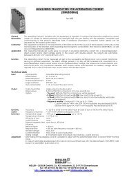
Data sheet GMA-2(pdf-document) - Müller + Ziegler GmbH & Co. KG
Data sheet GMA-2(pdf-document) - Müller + Ziegler GmbH & Co. KG
Data sheet GMA-2(pdf-document) - Müller + Ziegler GmbH & Co. KG
- No tags were found...

Create successful ePaper yourself
Turn your PDF publications into a flip-book with our unique Google optimized e-Paper software.
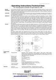
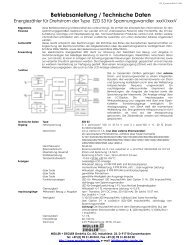
Generalinformation<strong>Co</strong>nformityApplicationsFunctionOperating manual / technical datafor limit value relay with display of type <strong>GMA</strong>-2<strong>GMA</strong>-2.doc 22.09.2008 07:2029This operating manual is included with the equipment as standard. It contains the information required forcorrect usage. It is aimed at trained personnel and specialist staff who are familiar with the assembly,installation and commissioning of the product described here. If additional information is required, furtherdetails can be requested by the address given below.This equipment conforms to the requirements of the Directive from the <strong>Co</strong>uncil of the European <strong>Co</strong>mmunity onthe harmonisation of the member states regarding electromagnetic compatibility, EMC Directive 2004/108/EC,as well as Low Voltage Directive 2006/95/EC.The electronic limit value relay <strong>GMA</strong>-2 with display is used to monitor alternating current or direct current as wellas alternating voltage or direct voltage. The alternating current values are measured as an effective value withany waveform. The measured value or limit value are displayed on a 2-digit LED display.The limit values can be set using buttons on the front of the unit in increments of 1%. Hysteresis, switch-on andswitch-off delay, closed-circuit or open-circuit current principle and min or max principle can also be set usingthe buttons. If the limit values are exceeded, this is indicated via light-emitting diodes. The limit value relay areinstalled in a housing of 22,5 mm of breadth and can be attached to a top hat rail in snapping them on.Technical dataInput Input value Direct current or direct voltage, alternating current or alternating voltage, theperiodic quantities are measured as effective values (up to crest factor 4) with anywaveform in the DC and AC range of 40 – 1000 HzSwitchingperformanceLimit value settingDisplayOverflowAccuracyTest voltageSwitching accuracy0 –99 %, can be set in 1 % increments2-digit LED display measured value 0 – 99 % of the measurement range limit value,2 red LEDs for exceeded limit valuesLED display indicates± 1 % of the measurement range limit value4 kV between measurement input and relay contacts as well as auxiliary voltage± 1 % of the measurement range limit valueHysteresiscan be set from 0 – 10 % of the limit valueSwitching timeSwitch delay< 400 ms at 10 % exceeding of limit valuecan be set from 0 – 99 secSwitching statusRelay contactclosed-circuit or open-circuit current principle can be selected2 change-over contactsTemperature range -15 to +20 to +30 to +55 °CInfluence of< 0.1 % at 10 KtemperatureOverload capacity 10 x voltage, max. 1000 V, 10 x current up to 20 mA, multiple of 2 above thatSwitching capacity max. 5 A, 250 V, 1250 VARegulations EMC DIN EN 61326Mechanical strength DIN EN 61 010 Part 1Electrical safety DIN EN 61010 Part 1Housing fully insulated, safety class II,at working voltages up to 300V (mains to neutral conductor) contamination level 2,measurement category CAT IIIat working voltages up to 600V (mains to neutral conductor) contamination level 2,measurement category CAT IIAuxiliary voltage230 V AC ± 15 %, 45-65 Hz, 2 VAOptions • 110 V AC ± 15 %, 45-65 Hz, 2 VA• 24 V DC, -15 % to +25 %, 2.5 W, (EMC DIN EN 61326 class A)• 6-30 VAC+DC or 36-265 VAC+DC, 2 VA, (EMC DIN EN 61326 class A)Weight200gMeasuring ranges Alternating current can be set Internal resistanceAC+DC fromtoeffective0.1 A 9.9 A 0.006 Ohmor 0.05 A 4.95 A (5 A corresponds to 100 %) 0.012 Ohmor 0.01 A 0.99 A 0.06 Ohmor 1 mA 99 mA 0.6 Ohmor 0.1 mA 9.9 mA 6 OhmAlternating voltageAC+DCeffective10 V 990 V (max. 600 V) 1 MOhmor 1 V 99 V 1 MOhmor 0.1 V 9.9 V 100 kOhmor 0.01 V 0.99 V 10 kOhmMÜLLER + ZIEGLER <strong>GmbH</strong> & <strong>Co</strong>. <strong>KG</strong>, Industriestr. 23, D-91710 Gunzenhausen, GermanyTel. +49 (0) 98 31.50 04 0, Fax +49 (0) 98 31.50 04 20http://www.mueller-ziegler.de , email: info@mueller-ziegler.de
<strong>GMA</strong>-2.doc 22.09.2008 07:2029Measuring ranges (continued) can be set Internal resistancefromtoDirect current DC 0.1 A 9.9 A 0.006 Ohmor 0.01 A 0.99 A 0.06 Ohmor 1 mA 99 mA 0.6 Ohmor 0.1 mA 9.9 mA 6 Ohmor 0.2 mA 19.8 mA (20 mA corresponds to 100 %) 3 Ohmor 4 mA 19.84 mA (20 mA corresponds to 100 %) 3 OhmDimensionsDirect voltage DC 10 V 990 V (max. 600 V) 1 MOhmor 1 V 99 V 1 MOhmor 0.1 V 9.9 V 100 kOhmor 0.01 V 0.99 V 10 kOhmor 1 mV 99 mV 1 kOhmor 0.6 mV 59.4 mV (60 mV corresponds to 100 %) 1 kOhmMountingElectrical<strong>Co</strong>nnectionFuseSnap-on fixing on standard 35 mm rail conforming to DIN EN 60715. The devices are suitable for dense patternmounting, at ambient temperatures of >45 °C, however, a distance of 10 mm is recommended. The mountingsite should be as free of vibration as possible and must not exceed an ambient temperature of 55 °C.The regulations on installing electrical systems must be observed.conforming to DIN 43807, via screw fitting max. 4 mm²Observe the correct polarity with DC versions when connecting DC as a measurement value!The polarity must be observed when connecting DC as the auxiliary voltage!The devices are fitted with short circuit-proof transformers; no overcurrent safety device is required for the limitvalue relay.<strong>Co</strong>nnectionWarning!MaintenanceCaution!Before starting any work on or in a device, it must be disconnected from the mains or switched to a voltagefreestate.The device is maintenance-free when used correctly.Servicing or maintenance work must only be carried out by trained specialist personnel.MÜLLER + ZIEGLER <strong>GmbH</strong> & <strong>Co</strong>. <strong>KG</strong>, Industriestr. 23, D-91710 Gunzenhausen, GermanyTel. +49 (0) 98 31.50 04 0, Fax +49 (0) 98 31.50 04 20http://www.mueller-ziegler.de , email: info@mueller-ziegler.de
<strong>GMA</strong>-2.doc 22.09.2008 07:2029Factory setting:for G1, limit value 25 %, hysteresis 1 %, switch delay if value is exceeded or undershot0 sec., closed-circuit principle, min contact.for G2, limit value 75 %, hysteresis 1 %, switch delay if value is exceeded or undershot0 sec., closed-circuit principle.Programming• Indicator for limit value G1, LED G1 is lit• Indicator for limit value G2, LED G2 is lit• press both buttons until both LEDs are flashing and the value indicator goes off toactivate the programming of the limit values• Select the limit values, button for limit value G1, button for limit value G2• Set the limit value using button (0 – 99 %),• Set the hysteresis using button (0 – 10 %)• Set the switch delay if the value is exceeded using the button(0 – 99 sec)• Set the switch delay if the value is undershot using the button(0 – 99 sec)• Switch function of the relay ⇒ open-circuit current principle ⇒ closedcircuitprinciple• can be selected using button• for limit value G2, save the settings and return to display modeFunction onlyavailable with • for limit value G1, select G1 = min – contact , G1 = max – contactlimit value G1!• can be selected using button• with limit value G1, save the settings and return to display modeCaution ! If no inputs are made for two minutes, the device switches back to display modewithout saving the changes. The settings are retained in the event of a power failure. Thelimit values are not being monitored when the limit values are being displayed or inprogramming mode!MÜLLER + ZIEGLER <strong>GmbH</strong> & <strong>Co</strong>. <strong>KG</strong>, Industriestr. 23, D-91710 Gunzenhausen, GermanyTel. +49 (0) 98 31.50 04 0, Fax +49 (0) 98 31.50 04 20http://www.mueller-ziegler.de , email: info@mueller-ziegler.de