Tech Sheet for Honeywell ML7285 Actuator - Categories On Acme ...
Tech Sheet for Honeywell ML7285 Actuator - Categories On Acme ...
Tech Sheet for Honeywell ML7285 Actuator - Categories On Acme ...

You also want an ePaper? Increase the reach of your titles
YUMPU automatically turns print PDFs into web optimized ePapers that Google loves.
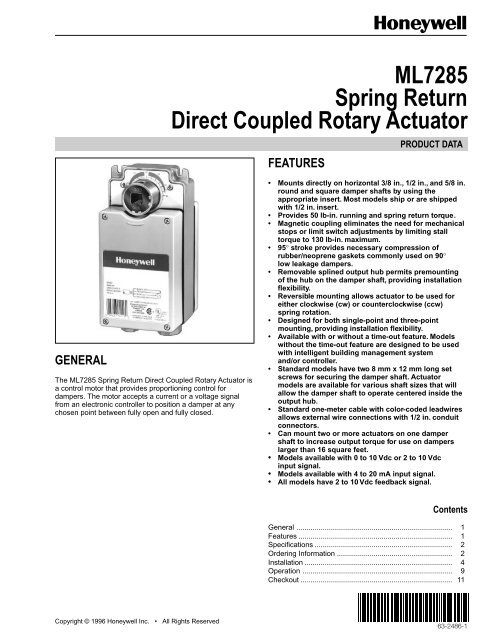
<strong>ML7285</strong>Spring ReturnDirect Coupled Rotary <strong>Actuator</strong>FEATURESPRODUCT DATAGENERALThe <strong>ML7285</strong> Spring Return Direct Coupled Rotary <strong>Actuator</strong> isa control motor that provides proportioning control <strong>for</strong>dampers. The motor accepts a current or a voltage signalfrom an electronic controller to position a damper at anychosen point between fully open and fully closed.• Mounts directly on horizontal 3/8 in., 1/2 in., and 5/8 in.round and square damper shafts by using theappropriate insert. Most models ship or are shippedwith 1/2 in. insert.• Provides 50 lb-in. running and spring return torque.• Magnetic coupling eliminates the need <strong>for</strong> mechanicalstops or limit switch adjustments by limiting stalltorque to 130 lb-in. maximum.• 95° stroke provides necessary compression ofrubber/neoprene gaskets commonly used on 90°low leakage dampers.• Removable splined output hub permits premountingof the hub on the damper shaft, providing installationflexibility.• Reversible mounting allows actuator to be used <strong>for</strong>either clockwise (cw) or counterclockwise (ccw)spring rotation.• Designed <strong>for</strong> both single-point and three-pointmounting, providing installation flexibility.• Available with or without a time-out feature. Modelswithout the time-out feature are designed to be usedwith intelligent building management systemand/or controller.• Standard models have two 8 mm x 12 mm long setscrews <strong>for</strong> securing the damper shaft. <strong>Actuator</strong>models are available <strong>for</strong> various shaft sizes that willallow the damper shaft to operate centered inside theoutput hub.• Standard one-meter cable with color-coded leadwiresallows external wire connections with 1/2 in. conduitconnectors.• Can mount two or more actuators on one dampershaft to increase output torque <strong>for</strong> use on damperslarger than 16 square feet.• Models available with 0 to 10 Vdc or 2 to 10 Vdcinput signal.• Models available with 4 to 20 mA input signal.• All models have 2 to 10 Vdc feedback signal.ContentsGeneral ............................................................................. 1Features ............................................................................ 1Specifications .................................................................... 2Ordering In<strong>for</strong>mation ......................................................... 2Installation ......................................................................... 4Operation .......................................................................... 9Checkout ........................................................................... 11Copyright © 1996 <strong>Honeywell</strong> Inc. • All Rights ReservedX-XX UL63-2486-1
<strong>ML7285</strong> SPRING RETURN DIRECT COUPLED ROTARY ACTUATORSPECIFICATIONSModels:<strong>ML7285</strong> Spring Return Direct Coupled Rotary <strong>Actuator</strong>s.<strong>ML7285</strong>A: High Torque (50 lb-in.) Direct CoupledRotary <strong>Actuator</strong> without auxiliary switches andwithout time-out function.<strong>ML7285</strong>C: High Torque (50 lb-in.) Direct CoupledRotary <strong>Actuator</strong> with two line voltage rated auxiliaryswitches, without time-out function.<strong>ML7285</strong>D: High Torque (50 lb-in.) Direct CoupledRotary <strong>Actuator</strong> without auxiliary switches and withtime-out function.<strong>ML7285</strong>F: High Torque (50 lb-in.) Direct CoupledRotary <strong>Actuator</strong> with two line voltage auxiliaryswitches and time-out function.Electrical Ratings:Power Input: 24 Vac ± 20%, 50/60 Hz.Power Consumption:<strong>ML7285</strong>A-C: 12 VA maximum at 24 Vac.<strong>ML7285</strong>D,F: 12 VA maximum at 24 Vac.Auxiliary Switch Ratings:120, 240 Vac: 3 AFL, 18 ALR, 1A pilot duty.Cable Ratings:Control: Standard models include nonplenumUL/CSA rated, 30V, 60°C, 20 gauge cable.Auxiliary Switch:UL/CSA rated 300V 90°C, 18 gauge cable.Control Inputs:0 to 10 Vdc or 2 to 10 Vdc or 4 to 20 mA.All models have 2 to 10 Vdc feedback signal.Torque Ratings (at Rated Voltages):Lift and Hold: 50 lb-in. (6 N•m).Breakaway Minimum: 50 lb-in. (6 N•m).Stall Minimum: 50 lb-in. (6 N•m) spring return.Stall Maximum: 130 lb-in. (15 N•m).<strong>Actuator</strong> Stroke:95° nominal ± 2°, mechanically limited.<strong>Actuator</strong> Timing at 90° Stroke:88 +/- 2 seconds synchronous at 60 Hz from 0°F to 140°F.106 +/- 2 seconds at 50 Hz.Spring Wind Timing (Upon Power Restoration <strong>On</strong>ly):100 seconds nominal at 60 Hz, 120 seconds at 50 Hz.Spring Return Timing:10 seconds minimum per 90° at 72°F no load;30 seconds maximum per 90° at 72°F at rated load;5 minutes maximum at -30°F at rated load.Ambient Temperature Range:-30°F to +140°F (-35°C to +60°C).Storage Temperature:-30°F to 150°F (-35°C to 65°C).Humidity:5 to 90 percent RH, noncondensing.Mounting:Mounts directly on horizontal 3/8 in. to 5/8 in. (12 to 16mm) round or square damper shaft. Minimum ShaftLength Required:3.5 in. (76 mm) when the shaft attachment is made onthe side of the actuator opposite the duct;0.65 in. (16 mm) when the hub is mounted on the shaftbe<strong>for</strong>e the actuator is installed. Most actuators areshipped with specifically sized hubs. Some modelscontain an assembly with assorted hub inserts.Mounting bracket is included with most models.Dimensions:See Fig. 1.Device Weight:4.0 lb (1.82 kg).Noise Rating (Driving only):45 dBA maximum at 1.0m.Spring Rotation:Clockwise (cw); counterclockwise (ccw) by reverse mounting.ORDERING INFORMATIONWhen purchasing replacement and modernization products from your TRADELINE® wholesaler or distributor, refer to theTRADELINE® Catalog or price sheets <strong>for</strong> complete ordering number, or specify:1. Model Number.2. Application.If you have additional questions, need further in<strong>for</strong>mation, or would like to comment on our products or services, please write orphone:1. Your local Home and Building Control Sales Office (check white pages of your phone directory).2. Home and Building Control Customer Logistics<strong>Honeywell</strong> Inc., 1885 Douglas Drive NorthMinneapolis, Minnesota 55422-4386 (612) 951-1000In Canada—<strong>Honeywell</strong> Limited/<strong>Honeywell</strong> Limitée, 155 Gordon Baker Road, North York, <strong>On</strong>tario M2H 2C9.International Sales and Service Offices in all principal cities of the world. Manufacturing in Australia, Canada, Finland, France,Germany, Japan, Mexico, Netherlands, Spain, Taiwan, United Kingdom, U.S.A.63-2486—1 2
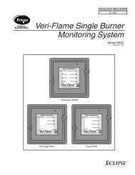
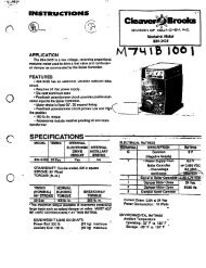
<strong>ML7285</strong> SPRING RETURN DIRECT COUPLED ROTARY ACTUATOR1-5/32 (29)1-17/32 (39)6-25/32 (173)3-1/16(79)8-9/32 (210)3-29/32(99)23/32(18)3-15/16 (100)1-21/32(42)3-1/2(89)1-5/8(41)1-9/32(32)3-29/32(99)CLEARANCEREQUIRED FOR SPLINED HUB MOUNTING1/2 (13)3/4 (19)13/64 (5)1-13/32 1-3/32(36)(28)135 o ± 15 o13/32(10)3/8(10)1-13/32 (36)5/16(8)4-13/32 (112)1-5/8 (41)10-13/32 (264)MOUNTING BRACKETM8257Fig. 1. Approximate dimensions of <strong>ML7285</strong> Spring Return Direct Coupled <strong>Actuator</strong> and mounting bracket in in. (mm).363-2486—1
<strong>ML7285</strong> SPRING RETURN DIRECT COUPLED ROTARY ACTUATORPosition Indicator:Mounted on actuator hub.<strong>Actuator</strong> Design Life:Full Stroke Cycles: 60,000.Repositions: 1,500,000.Spring Return Cycles: 7,500.Approvals:UL94-5V (Enclosure) Plenum rating.UL873 (Line voltage auxiliary switches).CSA: File Number E4436, Guide Number XAPX.Environmental Protection Ratings:NEMA1 standard with shaft in the horizontal position.Mounting Tab:For use with Universal mounting bracket.Accessories:205820A 3-Point Mounting Kit.205830A Crank-Arm Accessory.205753 Hub Sleeve, 3/8 in.205758 Hub Sleeve, 5/8 in.INSTALLATIONWhen Installing this Product…1. Read these instructions carefully. Failure to follow themcould damage the product or cause a hazardouscondition.2. Check the ratings and description given in thisspecification to make sure the product is suitable <strong>for</strong>your application.3. Installer must be a trained, experienced servicetechnician.4. After installation is complete, check out productoperation as provided in these instructions.CAUTION1. Disconnect power be<strong>for</strong>e installation to preventelectrical shock or equipment damage.2. Never turn motor output hub by hand or witha wrench.3. Do not install actuator in areas with acid fumes orother deteriorating vapors that can attack themetal parts of the actuator.4. Do not install actuator in areas with escaping gasor other explosive vapors that can be ignited by aspark from the actuator or attached accessories.LocationInstall the actuator in any location free from acid fumes orother deteriorating vapors that might attack the metal parts ofthe actuator. Make sure the location is not subjected toescaping gas or other explosive vapors that couldaccidentally be ignited by a spark from the actuator or itsattached parts.MountingThe <strong>ML7285</strong> Direct Coupled <strong>Actuator</strong> is designed to operatea damper by driving the damper shaft either cw orccw depending on damper design. All actuators areshipped in the fully closed (cw or ccw, depending on view)position.The <strong>ML7285</strong> Direct Coupled <strong>Actuator</strong> is designed <strong>for</strong> singlepointmounting when using an adapter bracket. Single-pointmounting is typically used when the actuator is mounted onthe damper frame.A mounting bracket (see Fig. 1) is provided with some modelsto aid in installing the actuator. The bracket can be bent inany shape in support the actuator at the correct height.The <strong>ML7285</strong> Direct Coupled <strong>Actuator</strong> can also be three-pointmounted, using the two front gear housing slots and theadapter bracket. Secure two screws through the two frontgear housing slots and position the adapter bracket to securethe rear of the actuator. Three point mounting is used <strong>for</strong> footmounting the actuator or mounting the actuator internally inthe duct, when direct shaft coupling is not possible.CAUTIONDo not use the actuator as a shaft bearing. Theactuator must be used only to supply rotationaltorque. To prevent damage to the actuator, avoid anyside loads to the actuator output coupling bearings.PreparationBe<strong>for</strong>e installing the <strong>ML7285</strong> on the damper shaft, determinethe opening direction of the damper shaft to determine thecorrect spring return rotation and correctly connect the wiring.The <strong>ML7285</strong> can be mounted to provide clockwise orcounterclockwise spring return. Reverse the actuator, ifnecessary, to provide the desired spring action.InstallationInstalling the <strong>Actuator</strong> and Mounting Bracket (SinglePoint Mounting)When the direction of the damper shaft rotation is determined(either cw or ccw ), proceed as follows: Place the <strong>ML7285</strong> Direct Coupled <strong>Actuator</strong> over thedamper shaft. Position the actuator <strong>for</strong> best access to the actuatordamper shaft locking screw. Install the mounting bracket (see Fig. 2) and adjust it tosupport the actuator at the correct height. Mark thescrew holes <strong>for</strong> installing the mounting bracket on thedamper housing. Remove the mounting bracket and actuator. Drill or center punch the starting holes <strong>for</strong> the mountingbracket screws (or use no. 10 self-tapping sheetmetal screws).Install the actuator in a location that allows enough clearance<strong>for</strong> mounting accessories and <strong>for</strong> servicing.63-2486—1 4
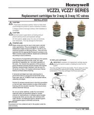
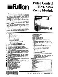
<strong>ML7285</strong> SPRING RETURN DIRECT COUPLED ROTARY ACTUATOR603090Installing the <strong>Actuator</strong> <strong>for</strong> Three-Point MountingThe <strong>ML7285</strong> Direct Coupled <strong>Actuator</strong> is designed withremovable hub sleeves to accommodate specific dampershaft sizes. Proper sleeve selection is necessary when threepointmounting is used to avoid excessive strain on the outputgear. Most <strong>ML7285</strong> <strong>Actuator</strong>s are shipped with a 1/2 in. hubsleeve. For field use, several hub sleeve sizes are available.See the Accessories listing in the Specifications section.Shaft sizes are stamped on the sleeves.The <strong>ML7285</strong> Direct Coupled <strong>Actuator</strong> can be mounted directlyon the motor shaft with the actuator in any position when theactuator housing is parallel with the damper housing or frame.(See Fig. 7.)M9386Fig. 2. Installing mounting bracket on <strong>ML7285</strong> DirectCoupled <strong>Actuator</strong>. Place the actuator and mounting bracket back intoposition over the damper shaft and install the mountingbracket screws. Tighten the two 8 mm x 12 mm long set screws firmlyagainst the damper shaft (maximum tightening torqueis 100 lb-in.).The <strong>ML7285</strong> Direct Coupled <strong>Actuator</strong> has a reversible outputhub. The hub is factory mounted on the top of the actuatorgear housing. When attaching to damper shafts less than 3.5in. (76 mm) long, or <strong>for</strong> ease of mounting, the output hub canbe mounted to the inside of the actuator gear housing. SeeFig. 3. Be careful when removing the retaining ring thatsecures the output hub to the actuator housing. Use aflatheaded screwdriver to pry the ring loose.Other possible mounting configurations and standardconnections are shown in Fig. 4 through 7.236160 906030DETENTINSERT30045INDICATORDETENTS.500.500M7228Fig. 3. Mounting hub to inside of actuator.563-2486—1
<strong>ML7285</strong> SPRING RETURN DIRECT COUPLED ROTARY ACTUATOR60 9060303001INDICATOR DETENTS1 COUNTERCLOCKWISE SPRING ROTATION ARROWM7230AFig. 4. <strong>ML7285</strong> <strong>Actuator</strong> mounted <strong>for</strong> counterclockwise spring rotation with the output hub inside the actuator.(NOTE: NEMA rating applies only with damper shaft in the horizontal position.)63-2486—1 6
.500<strong>ML7285</strong> SPRING RETURN DIRECT COUPLED ROTARY ACTUATOR60 90603030.500M7229Fig. 5. Standard direct coupled mounting of <strong>ML7285</strong> to a damper with counterclockwise spring rotation.763-2486—1
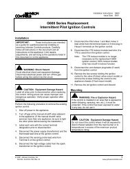
500<strong>ML7285</strong> SPRING RETURN DIRECT COUPLED ROTARY ACTUATORWiringCAUTIONDisconnect power supply be<strong>for</strong>e wiring to preventelectrical shock or equipment damage.3060 90.500.5006030All wiring must comply with local electrical codes, ordinancesand regulations. The <strong>ML7285</strong> is designed <strong>for</strong> use with aClass 2 power supply. Voltage and frequency of thetrans<strong>for</strong>mer used must correspond with the characteristics ofthe motor and those of the power supply. See Fig. 8 <strong>for</strong> atypical wiring connection.The <strong>ML7285</strong> has an aluminum die cast housing with twointegral cast bosses on the end of the device, tapped <strong>for</strong> 1/2in. conduit fittings. Some models are shipped with a waterseal in the conduit opening. When conduit is needed, removethe seal be<strong>for</strong>e routing the cable.<strong>ML7285</strong> models with Factory-mounted AuxiliarySwitches (See Fig. 9)<strong>ML7285</strong>C,F models have two nonadjustable line voltagerated spdt auxiliary switches that are factory set to makecommon to normally open at 12° and 82° rotation from thecounterclockwise stop. See Fig. 9.MOUNTINGBRACKETTO JUNCTIONBOX (UP TO3 FT AWAY)IMPORTANT<strong>Actuator</strong>s driving in parallel may not be synchronizedwith each other. In normal operation, if all actuatorsare driven to the fully open or fully closed position,the actuators are again synchronized.M7231Fig. 6. <strong>ML7285</strong> <strong>Actuator</strong> standard electrical connection.METERMODULATINGCONTROL SOURCE+–BROWNWHITEBLACKRED<strong>ML7285</strong>FEEDBACKINPUT24V COMMON24V HOT11L2L1 (HOT)24 VACPOWER SUPPLY. PROVIDE DISCONNECT MEANS AND OVERLOAD PROTECTION AS REQUIRED.M4443AFig. 8. <strong>ML7285</strong> typical wiring diagram.3006090603050012°INTERNALAUXILIARYSWITCH3A 24 VAC 82°COMMONNONCCOMMONNONCWHT/REDWHT/BLUWHT/YELBLACK/REDBLACK/BLUBLACK/YELM9384Fig. 7. <strong>ML7285</strong> <strong>Actuator</strong> can be mounted in any position.(NOTE: NEMA rating applies only with damper shaftin the horizontal position.)SWITCHES SHOWN AT ACTUATOR CLOSED POSITIONM7877Fig. 9. <strong>ML7285</strong>C,F wiring <strong>for</strong> auxiliary switches.63-2486—1 8
<strong>ML7285</strong> SPRING RETURN DIRECT COUPLED ROTARY ACTUATORConnecting <strong>ML7285</strong> <strong>Actuator</strong>s in Parallel<strong>ML7285</strong> <strong>Actuator</strong>s can be stacked on one damper shaft toincrease the output torque required to drive dampers largerthan 16 square feet.To make sure proper phasing occurs, connect all fourleadwires (red, black, brown and white) in parallel. Thenumber of actuators that can be wired in parallel is dependenton the trans<strong>for</strong>mer VA rating. Make certain that the connectedload does not exceed the current capacity of the controller/thermostat. See Fig. 10, 11 and 12.L1 (HOT)L2 1L1 (HOT)L21CONTROLLERFEEDBACK–BROWNWHITEREDBLACKBROWN<strong>ML7285</strong><strong>ML7285</strong>INPUTSIGNAL(T2)(T1)1L1 (HOT)L21L1 (HOT)L2CONTROLLERFEEDBACK+–BROWNWHITEREDBLACK<strong>ML7285</strong>INPUTSIGNAL(T2)(T1)11L1 (HOT)L2POWER SUPPLY. PROVIDE DISCONNECT MEANS AND OVERLOAD PROTECTION AS REQUIRED.WHITEREDBLACKINPUTSIGNAL(T2)(T1)M6483Fig. 12. <strong>On</strong>e 4 to 20 mA controller output and twoactuators with seperate trans<strong>for</strong>mers.L1 (HOT)L21CONTROLLERFEEDBACK+–BROWNWHITEREDBLACK<strong>ML7285</strong>POWER SUPPLY. PROVIDE DISCONNECT MEANS AND OVERLOAD PROTECTION AS REQUIRED.INPUTSIGNAL(T2)(T1)M6844Fig. 10. Two 0 to 10 Vdc, 2 to 10 Vdc, or 4 to 20 mAcontroller output and two actuators with seperatetrans<strong>for</strong>emrs.11L1 (HOT)L2CONTROLLERFEEDBACK–BROWNWHITEREDBLACKBROWNML7275ML7275INPUTSIGNAL(T2)(T1)OPERATIONThe <strong>ML7285</strong> Direct Coupled <strong>Actuator</strong> is designed to be usedin ventilating and air conditioning installations to operatedampers, ventilation flaps and louvers requiring up to 50 lb-in.torque. If the power fails, the actuator spring returns to thestart position. The actuator is designed <strong>for</strong> reversiblemounting. Arrows are molded into the covers to show thespring return direction. The larger cover shows acounterclockwise (ccw) spring rotation; the smaller covershows a clockwise (cw) spring rotation.The <strong>ML7285</strong> Direct Coupled <strong>Actuator</strong> is operated by aproportional controller. When using a proportional controller, theactuator is driven toward its fully open position when the inputsignal increases and drives toward the fully closed positionwhen the input signal decreases. The motor stops when theinput signal reaches the desired proportional control point.IMPORTANTThe <strong>ML7285</strong> is designed to respond toinstantaneous contact closures from a DDCController. Be careful not to short cycle the actuator.Unstable damper control can cause prematureactuator failure.WHITEREDBLACKINPUTSIGNAL(T2)(T1)1POWER SUPPLY. PROVIDE DISCONNECT MEANS AND OVERLOAD PROTECTION AS REQUIRED.M6842Fig. 11. <strong>On</strong>e 0 to 10 Vdc or 2 to 10 Vdc controller and twoactuators with seperate trans<strong>for</strong>mers.NOTE:<strong>Actuator</strong>s must be powered by a trans<strong>for</strong>merseperate from the controller power supply.963-2486—1
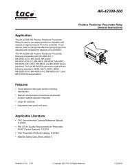
<strong>ML7285</strong> SPRING RETURN DIRECT COUPLED ROTARY ACTUATORThe actuator has a position indicator to depict shaft position.As the indicator moves with the shaft, it gives an angularrepresentation of the damper position. There are four distinctpositions where the indicator can be placed. The indicatorcan be removed (by first removing the output hub) to provideproper damper orientation. The indicator can be indexed toshow cw or ccw open or closed, using the detents that are90° apart. See Fig. 12. If the spring return position is the openposition, rotate the indicator until it points to 90 on the scale.If the spring return position is the closed position, rotate theindicator until it points to 0 (zero) on the scale. A detent can befelt at both stops. The detents maintain the indicator position.The <strong>ML7285</strong>D and <strong>ML7285</strong>F models provide a time-outfunction that removes power from the actuator sub-motor ifthe actuator remains in one position (closed, open or anyintermediate position) <strong>for</strong> longer than a nominal 100 seconds.This time-out function helps to extend actuator life.IMPORTANTThe <strong>ML7285</strong> was designed to provide 7500 springreturns. There<strong>for</strong>e, the actuator may be unpowereddaily <strong>for</strong> night shutdown control. However, rapidlycycling the actuator by removing control voltageleads to premature spring failure.FULLY COUNTERCLOCKWISE SPRING RETURN INDICATOR START POSITIONSPOINTER AT 90°POINTER AT 0°60 906060 9060303030300000DRIVE CLOCKWISE TO CLOSE(REVERSE ACTING)DETENT IN INSERTFULLY CLOCKWISE SPRING RETURN INDICATOR START POSITIONSPOINTER AT 90°DRIVE CLOCKWISE TO OPEN(DIRECT ACTING)DETENT IN INSERTPOINTER AT 0°60 906060 906030303030M72350000DETENT IN INSERTDRIVE COUNTERCLOCKWISE TO CLOSE (REVERSE ACTING)DETENT IN INSERTDRIVE COUNTERCLOCKWISE TO OPEN (DIRECT ACTING)M7235BFig. 12. <strong>ML7285</strong> indicator start positions.63-2486—1 10
<strong>ML7285</strong> SPRING RETURN DIRECT COUPLED ROTARY ACTUATORCHECKOUTThe <strong>ML7285</strong> Direct Coupled <strong>Actuator</strong> can be checked outeither directly or by using a controller.ImportantWhen power is interrupted, the actuator returns tothe normal starting position using the springmechanism. When power is restored, the controllerinput does not operate the actuator until the spring isfully wound and locked. The spring winding processtakes approximately 100 seconds, depending on thenumber of degrees of spring return remaining atpower interrupt (<strong>for</strong> example, 10° of spring returnremaining takes 10 seconds). (If the actuator is notin the closed position, it runs to the closed positionwhen the spring is winding. <strong>On</strong>ce the spring islocked in its fully wound position, the actuatorresponds to inputs on the white leadwire.Direct Checkout1. Mount the actuator <strong>for</strong> the required application (eithercw or ccw rotation to open the damper).2. Check the damper position and make sure 24 Vac ispresent on the red and black leadwires.3. Make sure the actuator spring is fully wound and lockedby applying power <strong>for</strong> at least 100 seconds.4. Apply the control signal to the appropriate leadwires(white and black) to move the damper to the oppositeposition. The <strong>ML7285</strong> should drive the damper.5. If the actuator does not run, verify that the actuator isproperly installed <strong>for</strong> either cw or ccwrotation.6. If the actuator is correctly installed and but not run,replace the actuator.Controller Checkout1. Adjust the setpoint of the controller to call <strong>for</strong> cooling.Observe the actuator.2. If the damper is closed, it should begin to open.3. If the damper remains closed, move the setpoint of thecontroller farther below the room temperature.4. If the damper still does not move, check <strong>for</strong> thepresence of 24 Vac in the input.5. Make sure the actuator spring is fully wound byapplying power <strong>for</strong> at least 100 seconds.6. If 24 Vac is present and the actuator does not operate,reverse the controller leadwires to determine if thedevice was miswired.7. If the wiring is correct and 24 Vac is present on theinput terminals but the actuator does not run, replacethe actuator.1163-2486—1
<strong>ML7285</strong> SPRING RETURN DIRECT COUPLED ROTARY ACTUATORHome and Building Control<strong>Honeywell</strong> Inc.<strong>Honeywell</strong> PlazaP.O. Box 524Minneapolis MN 55408-0524<strong>Honeywell</strong> Latin American DivisionMiami Lakes Headquarters14505 Commerce Way Suite 500Miami Lakes FL 33016Home and Building Control<strong>Honeywell</strong> Limited-<strong>Honeywell</strong> Limitée155 Gordon Baker RoadNorth York, <strong>On</strong>tarioM2H 2C9<strong>Honeywell</strong> Europe S.A.3 Avenue du BourgetB-1140 Brussels Belgium<strong>Honeywell</strong> Asia Pacific Inc.Room 3213-3225Sun Hung Kai CentreNo. 30 Harbour RoadWanchaiHong KongHelping You Control Your World63-2486—1 G.R. Rev. 7-96 Printed in U.S.A.12