Tech Sheet for Miscellaneous Controls (VF5602-42AA-NEW)
Tech Sheet for Miscellaneous Controls (VF5602-42AA-NEW)
Tech Sheet for Miscellaneous Controls (VF5602-42AA-NEW)

Create successful ePaper yourself
Turn your PDF publications into a flip-book with our unique Google optimized e-Paper software.
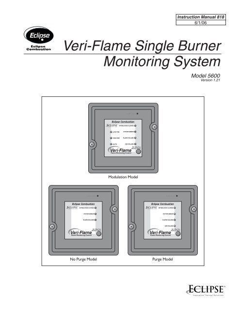
Instruction Manual 8186/1/06Veri-Flame Single BurnerMonitoring SystemModel 5600Version 1.21Modulation ModelNo Purge ModelPurge Model
CopyrightDisclaimer noticeCopyright 2006 by Eclipse, Inc. All rights reserved worldwide. This publication isprotected by federal regulation and shall not be copied, distributed, transmitted,transcribed or translated into any human or computer language, in any <strong>for</strong>mor by any means, to any third parties, without the express written consent ofEclipse, Inc., Rock<strong>for</strong>d, Illinois, U.S.A.In accordance with the manufacturer’s policy of continual product improvement,the product presented in this brochure is subject to change without notice orobligation.The material in this manual is believed adequate <strong>for</strong> the intended use of theproduct. If the product is used <strong>for</strong> purposes other than those specified herein,confirmation of validity and suitability must be obtained. Eclipse, Inc. warrantsthat the product itself does not infringe upon any United States patents. Nofurther warranty is expressed or implied.We have made every ef<strong>for</strong>t to make this manual as accurate and complete aspossible. Should you find errors or omissions, please bring them to our attentionso that we may correct them. In this way we hope to improve our productdocumentation <strong>for</strong> the benefit of our customers. Please send your correctionsand comments to our Marketing Communications Manager.Liability andWarrantyIt must be understood that Eclipse’s liability <strong>for</strong> its products, whether due tobreach of warranty, negligence, strict liability, or otherwise, is limited to thefurnishing of burner monitoring system replacement parts and Eclipse willnot be liable <strong>for</strong> any other injury, loss, damage or expenses, whether direct orconsequential, including but not limited to loss of use, income of, or damage tomaterial arising in connection with the sale, installation, use of, inability to useor the repair or replacement of Eclipse products.Eclipse, Inc., <strong>for</strong> a period of one year from shipment, warrants each Veri-Flameburner monitoring system to the original purchaser to be free from defectsin material and workmanship under normal use as defined hereafter. Anyoperation expressly prohibited in this Guide, any adjustment or assemblyprocedures not recommended or authorized in these instructions, shall voidthe warranty.Eclipse Veri-Flame Instruction Manual 818-6/06
About this manualAudienceScopeDocumentConventionsThis manual has been written <strong>for</strong> the people who select and install the productand the technicians who work on it. They are expected to have previous experiencewith this kind of equipment.This manual contains essential in<strong>for</strong>mation <strong>for</strong> the proper installation and operationof the Eclipse Veri-Flame Burner Monitoring System.Following the instructions in this manual should assure trouble-free installation andoperation of the monitoring system. Read this manual carefully. Make sure thatyou understand its structure and contents. Obey all the safety instructions.Do not deviate from any instructions or application limits in this manual withoutwritten consent from Eclipse Combustion, Inc.If you do not understand any part of the in<strong>for</strong>mation in this manual, do notcontinue. Contact your Eclipse sales office or Eclipse Combustion, Inc., Rock<strong>for</strong>d,Illinois.There are several special symbols in this document. You must know their meaningand importance.The explanation of these symbols follows. Please read it thoroughly.Danger:Indicates hazards or unsafe practices which WILL result in severepersonal injury or even death.Only qualified and well trained personnel are allowed to carry outthese instructions or procedures.Act with great care and follow the instructions.Warning:Indicates hazards or unsafe practices which could result in severepersonal injury or damage.Act with great care and follow the instructions.Caution:Indicates hazards or unsafe practices which could result in damage to the machineor minor personal injury.Act carefully.Note:Indicates an important part of the text.Read the text thoroughly.Eclipse Veri-Flame Instruction Manual 818-6/06
How to get helpIf you need help, you can contact your local Eclipse Combustion sales office.You can also contact Eclipse Combustion, Inc. at:1665 Elmwood RoadRock<strong>for</strong>d, Illinois 61103 USAPhone: 815-877-3031Fax: 815-877-3336E-mail: eclipse@eclipsenet.comhttp://www.eclipsenet.comEclipse Veri-Flame Instruction Manual 818-6/06
Table of ContentsAbout this manual ................................................................................... 3Table of contents ...................................................................................... 51234Introduction .................................................................................................. 8Product Description........................................................................................... 8Specifications .............................................................................................. 9Introduction............................................................................................................ 9Specifications.......................................................................................................... 9Dimensions............................................................................................................. 9DIP Switch Selection ............................................................................. 12Introduction............................................................................................................ 12DIP Switch Location............................................................................................. 12DIP Switch Access................................................................................................. 12No Purge DIP Switch Settings............................................................................ 12Modulation & Purge DIP Switch Settings......................................................... 13Function Summary ................................................................................. 14Introduction............................................................................................................ 14Standard Features.................................................................................................. 14Combustion Air Flow Check......................................................................... 14Main Fuel Valve Closed switch....................................................................... 14Low Fire Start................................................................................................... 14High Fire/High Fire Purge Check.................................................................. 14Recycle Mode.................................................................................................... 14Pilot Test Mode ................................................................................................. 14Interrupted or Intermittent Pilot.................................................................. 15Post Purge.......................................................................................................... 15Spark, Pilot Flame & Main Flame Separation.............................................. 15System Error & Lockout Conditions........................................................... 15High to Low Fire Purge Modulation Capability with High to LowFire Position Switch Interlocks...................................................................... 16Eclipse Veri-Flame Instruction Manual 818-6/06
4567Optional Features.................................................................................................. 16Pilot Test Mode Sequence............................................................................... 16Air Switch Input Hold..................................................................................... 16Remote Display & Power Supply.................................................................. 16Status Lights & Push-buttons.............................................................................. 17Interlocks Closed............................................................................................. 17Air Failure .......................................................................................................... 17System Error ..................................................................................................... 17Burner On.......................................................................................................... 17Flame Failure...................................................................................................... 17Low Fire.............................................................................................................. 17High Fire............................................................................................................. 17Auto .................................................................................................................... 17Test/Reset........................................................................................................... 17System Installation ................................................................................. 18Introduction............................................................................................................ 18Interlocks and Limit Switch Input...................................................................... 18Combustion Air Switch Input............................................................................. 18Ignition Wiring........................................................................................................ 18Low Fire Input........................................................................................................ 19Main Valve Closed switch..................................................................................... 19High Fire Input....................................................................................................... 19Remote Reset ........................................................................................................ 19Remote Display & Power Supply....................................................................... 19Purge and No Purge Wiring Diagram (Figure 5.1)......................................... 20Modulation Wiring Diagram (Figure 5.2)......................................................... 20Typical Connections <strong>for</strong> all Models (Figure 5.3)............................................. 21Sensor Installation ................................................................................... 24Introduction............................................................................................................ 24Sensor Wiring......................................................................................................... 24Flame Rods ............................................................................................................. 25Scanners .................................................................................................................. 25Scanner Sighting Considerations........................................................................ 25Test Procedures ......................................................................................... 26Introduction............................................................................................................ 26Flame Signal Strength............................................................................................ 26Minimum Pilot Test................................................................................................ 26Pilot Flame Failure Test......................................................................................... 27Main Flame Failure Test........................................................................................ 27Spark Sighting Test................................................................................................. 27Limits & Interlock Tests........................................................................................ 27Eclipse Veri-Flame Instruction Manual 818-6/06
89Maintenance & Troubleshooting .................................................. 28Introduction............................................................................................................ 28Maintenance............................................................................................................ 28Monthly Checklist................................................................................................. 28Yearly Checklist..................................................................................................... 28Troubleshooting..................................................................................................... 29LED Status............................................................................................................... 30LED Status & Conditions <strong>for</strong> No Purge Models (Table 8.1)........................ 30LED Status & Conditions <strong>for</strong> Purge Models (Table 8.2)............................... 31LED Status & Conditions <strong>for</strong> Modulation Models (Table 8.3)..................... 32Remote Display Messages ................................................................. 33Introduction............................................................................................................ 33Veri-Flame Operating Sequence (Table 9.1) ................................................... 34Remote Display Diagnostic Messages (Table 9.2).......................................... 38Appendix ......................................................................................................... 41Conversion Factors .............................................................................................. 41Illustrated Parts List ............................................................................................. 42Eclipse Veri-Flame Instruction Manual 818-6/06
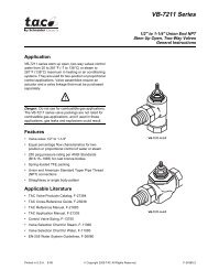
Introduction1ProductDescriptionThe Eclipse Combustion Veri-Flame Single Burner Monitoring System controlsthe start-up sequence and monitors the flame of single gas, oil, or combinationgas/oil burners. There are three different models to the Veri-Flame line: the nopurge, the purge and the modulation models. Each model features field selectabletrial <strong>for</strong> ignition (TFI). Each model is also available <strong>for</strong> use with four types offlame sensor: ultraviolet (UV), self-check UV, solid state UV/IR and flame rod.Required components are the Veri-Flame, matching wiring base and a flamesensor. Optional components include a remote display and cable, tester, andvarious scannner accessories.The Veri-Flame No Purge and Purge models are available in three differentseries—5602, 5603 and 5605. The 5602 Series is UL listed, CSA certified, FMapproved and GE GAP acceptable; the 5605 Series is UL listed, FM approvedand GE GAP acceptable. The 5603 Series is <strong>for</strong> 240VAC applications and isFM approved. Please see instruction manual 818-2 <strong>for</strong> European CE markedversions.The Veri-Flame Modulation model is available in two different series: 5602and 5603. Both series are capable of modulation (high and low fire purging). The5602 Series is UL listed, CSA certified, FM approved and GE GAP acceptable.The 5603 Series is <strong>for</strong> 240VAC and is FM approved.Figure 1 .1 Veri-Flame Single Burner Monitoring System(Purge Unit Shown)Eclipse Veri-Flame Instruction Manual 818-6/06
Specifications2IntroductionSpecificationsThis section gives a detailed overview of Veri-Flame specifications anddimensions.PARAMETERDESCRIPTIONSupply• Series 5602 & 5605: 120 VAC (+10%, -15%), 50/60 Hz standard.Series 5603: 240 VAC (+10%, -15%), 50/60 Hz standard.Internal power consumption: 12 VA (excluding external connected loads).Temperature Ranges Unit Model Nos. Temperature RangeVeri-Flame All Models -40° to +60°C (-40° to +140°F)90° U.V. Scanner 5600-90A -20° to +60°C (0° to 140°F)U.V. Scanner 5600-91 -20° to +125°C (0° to +257°F)NEMA4 UV Scanner 5600-91N4 -20° to +125°C (0° to +257°F)UV/IR Scanner 5600-92SC -20° to +80°C (0° to +176°F)Self-Check U.V. 5602-91 -20° to +60°C (0° to +140°F)Remote Display 5602DBP 0° to 50°C (32° to 122°F)Flame Failure Response 3 seconds ±0.5 seconds.Trial For Ignition (TFI)Pilot Interrupt (if selected) 10 seconds.No Purge & Purge Models:Series 5602 & 5603: 5 or 10 seconds selectable.Series 5605: 10 or 15 seconds selectable.Modulating Model: 5 or 10 seconds selectablePurge Time Selectable from 0-225 seconds in 15 second increments.Output Ratings <strong>for</strong> 120 VAC(maximum total connectedload not to exceed 15 amps)*Output Ratings <strong>for</strong> 240 VAC(maximum total connectedload not to exceed 15 amps)*UL, CSA Relay Contact RatingFunctionTerminals Inductive Load Resistive LoadGas Valve 3, 5 175VA, 1/10 HP 10 ampsIgnition 4 375 VA 10 ampsMotor or Contactor 8 470 VA, 1/2 HP 16 ampsControl Signal A, 10, 11, 12, 13 175VA 10 ampsRelay Contact RatingFunctionTerminalsResistive LoadValves, Ignition 3, 4, 5, 5 ampsMotors or Contactor 816 ampsAlarmA5 ampsControl10, 11, 12, 13 5 amps*Resistive loads have inrush currents approximately the same as steady state operation. The inductive inrush current mustbe less than 10 timesthe rating. The inrush current must not be applied more than once every 15 seconds.(continued onto next page)Eclipse Veri-Flame Instruction Manual 818-6/06
Specifications (continued)ParameterApprovals(See chart below.)Shipping WeightDescription• No Purge & Purge Models:Series 5602: UL listed, CSA certified, FM approved and GE GAP acceptable.Series 5603: FM approved.Series 5605: UL listed, FM approved and GE GAP acceptable.• Modulating Models:Series 5602: UL recognized (must be mounted in panel), CSA certified, FMapproved and GE GAP acceptable.Series 5603: FM Approved.• 1.4 kilograms (3 lbs.) <strong>for</strong> all Veri-Flame models.• 0.9 kilograms (2 lbs.) <strong>for</strong> Models 5602-10 & 5602-10-1 bases.• 1.2 kilograms (2.6 lbs.) <strong>for</strong> Model 5602-40 base.Approval In<strong>for</strong>mationUL Listed, File MP1537UL Recognized, File MP1537CSA Certified, File 007989FM Approved, File 3013812DimensionsVeri-Flame Unit/All Models76mm(3")133mm(5-1/4") SquareVeri-Flame Bases/Purge & No Purge ModelsModel Number 5602-10 Model Number 5602-10-1127mm(5")Square5.5mm(7/32") Dia.MountingHoles (4)Knockouts(10) <strong>for</strong>13mm (1/2"Conduit127mm(5")Square38mm(1-1/2")102mm(4") Square13mm(1/2")102mm(4") Square19mm(3/4")124mm(4-7/8")38mm(1-1/2")10Eclipse Veri-Flame Instruction Manual 818-6/06
Dimensions (continued)Veri-Flame/Modulating Model with Base Model Number 5602-4024mm(15/16")25mm(1")171mm(6-3/4")116mm(4-9/16")1 2 3 4 5 6 7 8 A D S2 S1 10 11 12 1340mm(1-9/16") 10mm (3/8") 5mm (3/16")213mm (8-3/8")Remote Display Model Number 5602-DBP102mm(4") Square*54mm(2-1/8")89mm(3-1/2")Square*= Alternate Mounting Locations*MountingBracket &Screw (2)WiringTerminals (2)GroundScrewContrastAdjustmentScrewEclipse Veri-Flame Instruction Manual 818-6/0611
DIP Switch Selection3IntroductionThis section details the location, selection and description of the Veri-FlameDIP switches, which allow <strong>for</strong> sequence and timing functions as well as systemconfiguration.CautionTo avoid electric shock, shut off the power supply when installingor removing any control device. Flame monitoring systems mustbe installed by a qualified, licensed technician.DIP Switch LocationDIP Switch AccessNo PurgeDIP Switch SettingsModulation & PurgeDIP Switch SettingsAll of the DIP switches are located in the back of each Veri-Flame unit (see Figure3.1 on page 13, or the photograph on page 8).To gain access to the DIP switches, the Veri-Flame must be separated from theback box (<strong>for</strong> visual reference, please refer to “Dimensions” on page 10). Thisseparation will expose the DIP switches on the back of the Veri-Flame unit.No Purge models of the Veri-Flame only use three of the eight DIP switches, asshown in the labels in Figure 3.2 on page 13. They are as follows:SW1: Recycling mode selection (On=Recycling; Off =Non-recycling)SW2: Pilot selection (On=Intermittent, where pilot remains on duringburner cycle; Off =Interrupted, where pilot valve closes after main burner isestablished).SW3: Trial-<strong>for</strong>-ignition (TFI) range selection (For 5602/5603 units: On =10seconds; Off =5 seconds. For 5605 units: On=10 seconds; Off =15 seconds).Modulation and purge models of the Veri-Flame use all of the eight DIP switches,as illustrated in Figure 3.2 on page 13. They are as follows:SW1: Recycling mode selection (On=Recycling; Off =Non-recycling)SW2: Pilot selection (On=Intermittent, where pilot remains on duringburner cycle; Off =Interrupted, where pilot valve closes after main burner isestablished).SW3: Trial-<strong>for</strong>-ignition (TFI) range selection (For 5602/5603 units: On=10seconds; Off =5 seconds. For 5605 units: On=10 seconds; Off =15 seconds).SW4 through 7: Purge time selection. Total purge time is the sum of each switchselected. If all are set off, the trial <strong>for</strong> ignition starts when the air switch inputcomes on.SW8: Post purge selection. (On=15 second post purge).12Eclipse Veri-Flame Instruction Manual 818-6/06
Function Summary4IntroductionStandard featuresInterlocks and LimitSwitch Input (Terminal 7)Combustion AirSwitch Input (Terminal 6)Main Fuel Valve ClosedSwitch (Terminal V)Low Fire StartThis section describes the features of the Veri-Flame. It is divided into threecategories: Standard features, Optional features and the LED Indicator Lights onthe front cover. Refer to Figure 5.5 <strong>for</strong> sequence diagrams.The following function features are standard on the Veri-Flame models as noted:This input is considered the normal operation control or run input to theVeri-Flame system. Interlocks are generally pressure or temperature switcheswhich, when activated, start the burner. Limit switches are generally pressure,temperature and other switches which, when activated, stop the burner. Theinterlocks and limit switches are wired in series. A break in this circuit will shutthe burner down, but will not produce an alarm.For purge and modulation models: This input is <strong>for</strong> monitoring thecombustion air switch separately from other interlocks and limits. The Veri-Flame checks the air flow switch input is open be<strong>for</strong>e start-up, closed duringoperation, and open again at burner shutdown, thus preventing operation withan air switch that is defective, maladjusted or jumped. This input has about a 2second delay to filter out and ignore a momentary interruption.The input will be proven open be<strong>for</strong>e start-up and after shutdown. If the inputis improperly powered be<strong>for</strong>e the fan output is energized, the system errorlight will blink. The input must de-energize within 30 seconds or the Veri-Flamewill lockout.After the fan output has energized, the air switch input must be made within 10seconds. If not proven, then the system will lockout, the alarm output and theair failure light will come on. However, if the unit has the optional air switchinput hold feature, the sequence is held indefinitely without causing a lockout.When the air switch input is made, then the sequence continues.If the air switch opens during the main firing cycle, the system will eitherlockout or recycle, depending on the DIP switch recycle selection.Purge and No-Purge models: the Veri-Flame can be interlocked with themain valve closed switch. This feature checks the switch position be<strong>for</strong>e startupand after shutdown to insure proper valve operation when the jumper onthe base is cut.For modulation models: when wired, the system checks <strong>for</strong> the low firestart position prior to light-off.14Eclipse Veri-Flame Instruction Manual 818-6/06
Main Fuel Valve Closed/High Fire Purge Check(Terminal D)Recycle ModePilot Test ModeTest Mode(Button In)Run Mode(Button Out)Interrupted orIntermittent PilotPost PurgeSpark, Pilot Flame &Main Flame SeparationSystem Errors &Lockout ConditionsFor modulation models: This feature is enabled when the jumper on thebase is cut. The system checks that the high fire position switch and the mainvalve closed switch are both made at the end of the high fire purge.For all models: when selected, the Veri-Flame will restart the sequenceafter flame or air failure. The recycle mode allows the system to re-initiatethe start-up sequence automatically provided the main burner has beenoperating <strong>for</strong> at least 35 seconds. If the pilot flame fails to light duringrecycling, the system will lock out and annunciate a pilot flame fail. If the recycleis successful and the main burner is operational <strong>for</strong> at least 35 seconds,the system is ready <strong>for</strong> another recycle. At no time will the system recycle inthe event of pilot flame fail.For all models: this mode is entered by depressing the TEST/RESET buttonon the front cover. In the pilot test mode, the Veri-Flame will hold the sequenceonce the pilot flame is established (i.e., the main valve is not energized). Whenin the pilot test mode, the green “Interlocks Closed” light blinks.To exit the pilot test mode, push the TEST/RESET button again and the Veri-Flame will exit the pilot test mode (the green “Interlocks Closed” light stopsblinking but remains lit) and you must restart the sequence.For all models: pilot mode is selected using the DIP switch SW2. An interruptedpilot shuts off 10 seconds after the main valve opens. An intermittentpilot continues during the entire main flame firing cycle.For purge and modulation models: post purge is enabled by DIP switchSW8. A post purge maintains the combustion air fan output <strong>for</strong> 15 secondsafter the interlocks and limit switch input have opened.For all models: during the trial <strong>for</strong> ignition period (TFI), the pilot valve andignition coil remains energized. If a flame signal is present at the end of theTFI, the pilot output remains on and the ignition coil is de-energized. After afive second delay to prove the pilot flame, the main gas valve is energized.A system error (illuminated by the red “System Error” LED on the front cover)prevents gas ignition. The unit will continue its sequence after the error iscleared. A lockout condition energizes the alarm output and de-energizesthe gas valve and ignition outputs. The unit must be reset to clear the alarmand start the sequence. To reset, the button must be pressed twice so thatthe button is in the out position.The following system errors result in immediate lockout conditions:1) Wiring error which puts external voltage on the output terminals (<strong>for</strong>all models).2) Welded internal contacts or other malfunctions in the Veri-Flame (<strong>for</strong> allmodels).3) Main fuel valve (<strong>for</strong> all models)–open after cycle shutdown or be<strong>for</strong>estart-up. The system error light blinks twice and then remains on. Thefan output terminal 8 will energize.Eclipse Veri-Flame Instruction Manual 818-6/0615
System Errors &Lockout Conditions(Continued)4) Low fire fail (<strong>for</strong> modulating model)–low fire switch open prior to trial<strong>for</strong> ignition.5) High fire fail (<strong>for</strong> modulating model)–high fire switch is not closed at theend of high fire purge.The following situations will result in a lockout condition:6) Air failure (<strong>for</strong> purge and modulation models) – loss of combustionair anytime during the operational cycle. The Air Failure LED will be on <strong>for</strong>this condition. (See “Recycle Mode” on page 14)7) Pilot flame fail (<strong>for</strong> all models) loss of flame during the trial <strong>for</strong> pilot ignitionperiod. The Flame Failure LED will be on <strong>for</strong> this condition.8) Main flame fail (<strong>for</strong> all models) loss of flame during the main burner trial<strong>for</strong> ignition or run period (recycling not selected). The Flame Failure LEDwill be on <strong>for</strong> this condition.The following result in lockout conditions after 30 seconds, the system errorlight blinks about 14 times and then remains on:9) If a flame is detected out of sequence, which may be caused by:a) a faulty scanner (<strong>for</strong> all models);b) electrical interference on the sensor wiring (<strong>for</strong> all models);c) a flame exists in the burner or in the line of sight of a scanner, due toa gas leak, product fire or other condition (<strong>for</strong> all models).10) Air flow switch closed be<strong>for</strong>e start-up (<strong>for</strong> purge and modulationmodels).High to Low Fire PurgeModulation Capabilitywith High to Low FirePosition Switch InterlocksFor modulation models: the modulation feature incorporates a high firepurge time and a low fire purge time into the purge sequence. This featureallows the Veri-Flame to sequence internal dry contacts which can be used bythe customer requiring a high fire purge of the combustion chamber be<strong>for</strong>eignition.The high fire and low fire purge times are selectable by means of DIP switches(see Section 3, “DIP Switch Settings” on page 12):SW4................................15 secondsSW5................................30 secondsSW6................................60 secondsSW7............................. 120 secondsThe selected times are additive and apply to both the high fire and low fire purgetimes (that is, high and low fire times are always identical).The modulation terminals will sequence as follows:Sequence StepInternal Contact ConnectionsPower Off Terminal 10 (Common) Terminal 12 (Low Fire)Power On, Limits Open Terminal 10 (Common) Terminal 12 (Low Fire)Purge To High Fire Terminal 10 (Common) Terminal 13 (High Fire)Purge To Low Fire Terminal 10 (Common) Terminal 12 (Low Fire)Automatic Modulation Terminal 10 (Common) Terminal 11 (Auto)Alarm and Lockout Terminal 10 (Common) Terminal 12 (Low Fire)The purge to high fire sequence does not start until the air switch input is on.The Automatic step occurs when the burners are operating and allows theburner firing rate to be controlled by an automatic temperature controller.16Eclipse Veri-Flame Instruction Manual 818-6/06
Optional featuresAir Switch Input HoldRemote Display &Power SupplyManual Reset onPower OutageStatus Lights &Push-buttonInterlocks ClosedAir FailureSystem ErrorFlame FailureLow FireHigh FireAutoTest/ResetFlame SignalThe following features are available on select models, or when optional equipmentis purchased.For purge/modulation models: holds the sequence indefinitely until airswitch input is confirmed without affecting the air failure function and causinga lockout.The model 5602DBP operates on 120VAC and has a keypad <strong>for</strong> resetfunction. The display is door panel mounted and features a liquid crystaldisplay in a ¼ DIN housing. The unit connects to the Veri-Flame by acable to the flame signal test jack, and receives a serial communicationon each sequence state change. The display incorporates the followingfunctions:1) Provides status messages <strong>for</strong> the Veri-Flame sequence (see section9).2) Indicates lockout conditions when they occur, as well as theamount of time into the sequence when the lockout occurred(see section 9).3) Provides continuous monitoring of the burner’s flame signalstrength and run time during main burner operation.This optional feature requires a reset on initial application of power or after aninteruption of power. The system error light blinks rapidly (about 4 times persecond) and a remote display will show “PUSH RESET TO START”. The resetbutton must be pressed in and out to start. Do not order this option if theVeri-Flame is mounted inside an enclosure.All of the status lights and the TEST/RESET push-button are located on the frontcover of the Veri-Flame. This section describes their respective functions.For all models: this green LED illuminates when the operation limits are made.These limits are wired in series to terminal 7. This input becomes energized tobegin the burner sequence. When in the test mode, this LED blinks (see “PilotTest Mode” on page 15).For purge and modulation models: this red LED illuminates whenevercombustion air is lost during the operational cycle of the Veri-Flame.For all models: this red LED illuminates when a system error is detected (see“System Errors & Lockout Conditions” on pages 15-16).For all models: this red LED illuminates when a pilot or main flame fails.For modulation models: this yellow LED illuminates during the low fireperiod of the purge cycle.For modulation models: this red LED illuminates during the high fire periodof the purge cycle.For modulation models: this green LED illuminates during the automaticperiod which occurs 20 seconds after the main valve is energized.For all models: this push-button is used to activate the pilot test mode or toreset the Veri-Flame unit.For all models: this red LED is located behind the signal test port and illuminateswhen a flame signal is present.Eclipse Veri-Flame Instruction Manual 818-6/0617
System Installation5IntroductionIn this section, the necessary procedures are detailed to integrate a Veri-Flameinto a burner system; Figures 5.1 and 5.2 illustrate the various terminal stripsmentioned.Note:Shut off the power supply be<strong>for</strong>e the Veri-Flame is removed or replaced fromthe base.Caution:Installation and maintenance must con<strong>for</strong>m with the National Electrical Codeand all other national and local codes and authorities having jurisdiction. Flamemonitoring systems must be installed by a qualified, licensed technician.Interlocks andLimit Switch InputCombustion AirSwitch InputTo Fan OutputTerminalFAN3-Way Solenoid ValveDe-energizedTo Fan OutputTerminalFANAirSwitchOpenToBurnerAirSwitchClosed3-Way Solenoid ValveEnergizedToBurnerWire external interlock, control, and limit switches in series to this input. Guardagainst induced voltage levels to wiring connected to this input. In some extremewiring runs, reduction of induced voltages may require a load (relay or light)connected to terminal 7 to avoid system error lockouts. This input is the powersource <strong>for</strong> the valve and ignition output terminals. Be sure all switches wired tothis input can handle the current required by the total of all loads connected toterminals 3, 4, and 5.For purge and modulation models: Wire any switches and contacts in seriesto this terminal <strong>for</strong> proving air flow function and relating to the air failurelight. Power must not be immediately present at terminal 6 when power is firstapplied to terminals 1 or 7.If this terminal is not used, place a jumper between the combustion bloweroutput (terminal 8) and the air switch input (terminal 6).If the combustion air blower is controlled outside of the Veri-Flame system, thena three way solenoid valve must be connected between the air switch port andthe blower sensing port. The valve de-energized state should vent the switchto ambient pressure. The energized state then connects the air switch to theblower sensing port. Power the valve from the blower ouput terminal 8. If acceptedby local codes, the air switch could be wired between the combustionblower output and the air switch input. Connecting the air switch in this mannerwill satisfy the open contact (air short) check on the switch.18Eclipse Veri-Flame Instruction Manual 818-6/06
Ignition WiringLow Fire InputMain ValveClosed SwitchHigh Purge InputRemote ResetRemote Display &Power SupplyRoute ignition wiring a sufficient distance from all sensors and other low voltagewiring to avoid electrical interference, which may cause erratic operation of theVeri-Flame system. Keep the high voltage wire run from the ignition trans<strong>for</strong>meras short as possible. The best condition is to mount the ignition trans<strong>for</strong>merclose to the burner and keep a low impedance path from the burner ground tothe case of the trans<strong>for</strong>mer. Make sure the high voltage lead and ground returnpaths do not create a loop antenna around the Veri-Flame and sensor wiring.For modulation models: it is possible to wire the system <strong>for</strong> checking lowfire start position prior to pilot ignition. To use this feature, the low fire startswitch must be connected between terminal 3 and the pilot valve (see Figure5.2). On direct spark burners, a by-pass contact must be wired around the lowfire switch, see relay and contact CR in Figure 5.3.The system can be wired to check <strong>for</strong> the main valve closed switch on the maingas valve prior to start-up and after the end of the burner cycle.For purge and no purge models: the main valve closed switch must be connectedto Terminal V and the jumper in the base must be cut (see Figure5.4 on page 22).For modulation models: the main valve closed switch must be wired in seriesbetween the air flow switch and the high purge damper switch (see Figure 5.1on page 20). To use this feature, the jumper in the base must be cut.For modulation models: the system can be wired to check <strong>for</strong> high purgeposition during the high fire purge portion of the sequence. To use this feature,the red jumper in the base must be cut and the high purge position switchmust be connected from terminal 6 to D. If this feature is not used, the jumperin the base remains intact or a jumper must be installed between terminals 1and D. Please note that the yellow jumper on the base has no effect whethercut or intact.This feature permits remote mounting of a switch to reset the Veri-Flame. To usethis feature, a normally closed remote reset switch must be wired so power isinterrupted to terminal 1. When it is depressed or actuated, the connection toterminal 1 is momentarily interrupted and resets the Veri-Flame.Wire the display according to figure 5.3. Mount through a ¼ DIN cutout usingthe two supplied brackets in either the top and bottom or the side slots.Locate the display and wiring to minimize electrical interference. Applying anddisconnecting the display power supply should coincide with power to terminal1 of the Veri-Flame. Use the appropriate cable (Eclipse part #20318) to connectto the test jack and to the S2 terminal of the Veri-Flame wiring base. Do notattempt to parallel the test jack signal to other devices when using a remotedisplay. The LCD display contrast can be adjusted on the back with a small bladescrewdriver.Note:power <strong>for</strong> terminal 7 of the VeriFlame should not flow through the R1-R2contact when load currents exceed 5 amps.Eclipse Veri-Flame Instruction Manual 818-6/0619
No Purge ModelsFigure 5.1 No Purge and Purge Wiring DiagramsPurge Models5602/5605:120 VAC50/60 HZ5603:240 VAC50/60 HZ5602/5605:120 VAC50/60 HZ5603:240 VAC50/60 HZ15 AFuseOn/Off12Piloted Burner15 AFuseOn/Off12Piloted Burner3Pilot3PilotInterlocks & Limits457IgnitionMainAir Flow Switch456IgnitionMainProof ofClosureAVS1S2AlarmInterlocks& LimitsProof of Closure78AVFanAlarmS1GS2GFigure 5.2 Modulation Wiring Diagram5602/5605:120 VAC50/60 HZ5603:240 VAC50/60 HZ15 A. FuseOn/Off1Air FlowCut RedJumperTo ActivateTerminal D.2345Low Fire ProvingPilotIgnitionMain6Interlocks& Limits78FanProof ofClosureHigh PurgeDamperSwitchADS2S110111213FlameSensorTerminalsCommonAutomaticLow FireHigh FireAlarmSee the “High toLow Fire PurgeModulationCapability” sectionon page 16 <strong>for</strong>contact connections.G20Eclipse Veri-Flame Instruction Manual 818-6/06
Figure 5.3 Typical Connections For All Models21S1S2Self Check U.V. 5602-91(Requires 5602-91-7 cable)ABCDModel 5602 DBP120 VAC Remote Display12V+12V-Tx Rx120V 120VN LCable#20318to 120 VACR1R2GPLUGTo 1Flame SignalTest JackTo S2Veri-Flame21S1S2Self-Check U.V. 5602-91(Requires 5602-91-7 cable)<strong>for</strong> 240 VAC Veri-Flame240VT1120VABCDSolid State U.V. / I.R.WhiteS1BlackScannerS2G ShieldS1S2BlueFlame RodFlame RodT1Third party trans<strong>for</strong>mer required. Must be at least 25 VA.S1S2U.V.Blue (Signal)Yellow (Neutral)U.VorI.R.No Purge & PurgeDirect Spark345MAINIGNITIONNote: Intermittent pilot mustbe selected, DIP-SW2 = ONNeutral345ModulationDirect Spark withLow Fire StartLow Fire ProvingCRCRMAINIGNITIONNeutralNote: Intermittent pilot must be selected, DIP-SW2 = ONCR is a control relay used to bypass the low fire switch afterthe burner is lit.Notes <strong>for</strong> Figures 5.1, 5.2 & 5.3:1. Ground, shielding and conduit must not be connected to terminal S2.2. Control circuit wires must meet 90°C (194°F) specification minimum and mustbe No. 16 AWG or larger and in accordance with all applicable codes.3. Flame sensor wires must be individually run in their own separate conduit; flamesensor wires CANNOT be run together in a common conduit or wireway (SeeSection 6).4. Flame signal should read between 4 and 10 VDC with a digital volt meter. Drop offis approximately 4.0 VDC. Positive test jack point is on the cover marked “FlameSignal” with negative point being the S2 or ground.5. Purge time, TFI, intermittent/interrupted pilot, and recycle/non-recycle selectionsare made with a DIP switch located on the rear plate of the control unit.6. Neutral must be grounded.Eclipse Veri-Flame Instruction Manual 818-6/0621
Figure 5.4 Purge and No Purge BasesModel Number 5602-10 Model Number 5602-10-1P256S2S178P3P1Gnd34V21AJumperGndNOTE: Ground Terminaln not present in plastic base.3211321P3P2P1Jumper5 6 S2 S1 7 8 A 1 2 V 4 3646417V62S2S1Internal DiagramPurge & No-purgeP156P3P2P21FanP112Alarm P14P1 Fault Pilot P336Ign P3J15Main P3P33SupervisorFlame SignalAmplifierJackNote: No purge models do not use 6 & 8.8A345Modulating BaseModel Number 5602-401Internal DiagramModulation ModelP1P15 Fan 1862Red32113216464P3P2P11J1J217D62Alarm P14P1 Fault Pilot P33 6Ign P3522KMain P322K P3 34P32P22 SupervisorA345GndJumper1 2 3 4 5 6 7 8 A D S2 S1 10 11 12 13S2S110P21J24Flame SignalAmplifierJ22J21J23JackAuto11LowHigh121322Eclipse Veri-Flame Instruction Manual 818-6/06
OutputsInputsTerminal13457VFunctionControl PowerPilot ValveIgnitionMain ValveInterlocksPOVCFigure 5.5 Sequence DiagramsStartTFIPilotTrialFlameCheckPilot Off35 SecondsMainTrial10 Sec(Interrupted)RecyclePermittedFiringCyclePilot OffEnd(Intermittent)OutputsInputsTerminal1345867VFunctionControl PowerPilot ValveIgnitionMain ValveFanAir SwitchInterlocksPOVCStart10SecAir ProvenPurgeFlameTFI Check5 SecPilotTrialPilot Off35 SecondsMainTrial10 Sec(Interrupted)FiringCyclePilot OffRecyclePermitted(Intermittent)PostPurge15 SecEndOutputsInputsContinuityBetweenModulationTerminalsTerminal1345867D310 to 1210 to 1310 to 11FunctionControl PowerPilot ValveIgnitionMain ValveFanAir SwitchInterlocksHigh Fire & POVCLow Fire SwitchLow Fire PurgeHigh Fire PurgeAutomaticStart10SecAir ProvenHigh FirePurgeLow FirePurgeFlameTFI Check5 SecPilotTrialPilot OffMainTrial10 Sec20 Seconds35 Seconds(Interrupted)Firing CyclePilot OffRecyclePermitted(Intermittent)EndPostPurge15 SecEclipse Veri-Flame Instruction Manual 818-6/0623
Sensor Installation6IntroductionThis section describes the proper wiring, installation and sighting considerations<strong>for</strong> all sensors that can be used with a Veri-Flame.WarningIncorrect sensor installation may cause the sensor to generatea false flame signal, possibly resulting in the collection ofunburned fuel in the combustion chamber. This unburnedfuel creates the potential <strong>for</strong> explosions which can result ininjuries, death and property damage. Be certain that theflame sensor detects acceptable pilot and main flames only.Sensor WiringFlame RodsRoute sensor wiring a sufficient distance from ignition and other high voltageor high current wiring to avoid electrical interference. Interference from groundcurrents, nearby conductors, radio-frequency emitters (wireless divices), andinverter drives can induce false flame signals. Shielded cables can help reduceinterference with the shield connected to ground at the control end only. Thewire type and its capacitance (picofarads or microfarads) to ground may causelow signal problems, so a grounded shield may decrease the signal due to thecable’s internal capacitance. Multiple U.V. tube-type sensor leads run togetherwithout shielding may interfere or “cross talk”, so the shield or flexible armormust be grounded to prevent this situation. For flame rod sensor runs approximately100 feet (30 meters) or greater, use Eclipse part number 21741coax cable. To achieve the maximum wiring distance, the shield should not begrounded (keep in mind that an ungrounded shield provides less protectionagainst electrical interference).Note:Unshielded sensor wiring must not be run in common with other wires; itmust be run in separate conduit. Multiple unshielded flame sensorwiring must not be run together <strong>for</strong> long lengths in a common conduit orwireway. Use #14 to #18 AWG wire suitable <strong>for</strong> 90°C (194°F) and 600volt insulation, or a better grade if required by the application. Multipleshielded flame sensor cables can be run in a common conduit.Flame rods should be used only on gas burners. They accumulate soot from oilburners, causing nuisance shutdowns and unsafe operating conditions.See the burner manufacturer’s literature <strong>for</strong> flame rod mounting location. Wheninstalling flame rods, please consider the following:24Eclipse Veri-Flame Instruction Manual 818-6/06
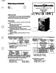
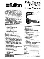
Figure 6.1 Flame Rod PositionWRONGRod DetectsWeak PilotPILOTScannersCORRECTRod DetectsOnly StrongPilot Flame1) Keep the flame rod as short as possible and at least 13 mm (1/2”) away fromany refractory.2) Position the rod into the side of both the pilot and main flames, preferablyat a descending angle to minimize drooping of the flame rod against burnerparts, as shown in Figure 6.1. Flame rod position must adequately detectthe pilot flame at all burner draft conditions. Extend the rod 13 mm (1/2”)into nonluminous flames, such as blue flames from burning an air/gas mixture.For partially luminous flames, such as atmospheric air/gas mixtures, placethe rod at the edge of the flame.3) Provide a burner/flame grounding area that is at least four times greater thanthe flame rod area contacting the flame. The flame rod/burner ground ratioand position of the rod in the flame may need adjustment to yield maximumflame signal strength.4) Ignition interference from the spark plug may increase or decrease the flamesignal strength. Reversing the ignition trans<strong>for</strong>mer primary leads may reducethis effect. Changing the spark gap or adding grounding area between theflame rod and spark plug may eliminate the interference.WarningUse only Eclipse scanner models as listed in the IllustratedParts List at the end of this document.When installing scanners, please consider the following:1) Position the scanner within 457 mm (18”) of the flame. Consult factory <strong>for</strong>longer distances.2) Bushing threads are 1/2 inch F.N.P.T. <strong>for</strong> all scanner models except 5602-91which has 1 inch F.N.P.T. bushing threads.3) The ambient temperature limits of each scanner varies; check the literature<strong>for</strong> the specific scanner model. For higher temperatures, use Eclipse heatblock seal 23HBS <strong>for</strong> ½” N.P.T. scanners and if necessary, add cooling purgeair.4) An optional magnifying lens may also be used to increase the flame signalstrength in difficult sighting situations.Scanner SightingConsiderationsFigure 6.2 U.V. Scanner SightingMAINBURNERScannerSightLineSCANNER1/3 ofFlame LengthAim scanners at the third of the flame closest to the burner nozzle, as shown inFigure 6.2 (oil flames typically have less UV radiation in the outer flame). Thescanner should view the intersection of the pilot and main flames. When sightingscanners, please consider the following:1) If possible, sight the scanner away from the ignition spark. Sighting the sparkor its reflections from burner internals may lead to a misdiagnosis of shutdownsduring burner ignition. If necessary, use a scanner orifice to reducespark pickup.2) Do not allow the scanner to detect a pilot flame that is too small to ignitethe main burner.3) Per<strong>for</strong>m a minimum pilot test when installing or adjusting any pilot or mainburner system; see “Minimum Pilot Test” on page 26.4) Solid State UV/IR scanner model 5600-92SC may better detect oil flames.When used, aim the scanner at the outer oil flame <strong>for</strong> flicker detection.Eclipse Veri-Flame Instruction Manual 818-6/0625
Test Procedures7IntroductionThis section describes the test procedures that must be per<strong>for</strong>med after installationto insure that the Veri-Flame is operating properly; these procedures aremandatory.Flame Signal StrengthMinimum Pilot TestInsert the positive probe of a 0-15 VDC, digital volt meter into the test pointon the front cover of the Veri-Flame; connect the negative probe to S2 or ground.A good flame signal strength will read between 6 and 11 VDC; anything below4 VDC is inadequate. Also, the red LED inside the test point illuminates whena flame signal is indicated.Run the following test procedures to ensure that the sensor will not detect apilot flame too small to reliably light the main flame:1) Manually shut off the fuel supply to the burner, but not to the pilot.2) Start the system normally.3) To enter the pilot test mode, depress the test/reset button located in thelower right corner on the front cover.4) The control will hold the operating sequence at the pilot flame step. Measuresignal strength as described above.5) Reduce pilot fuel until the flame relay drops out. Increase pilot fuel until theflame signal is greater than 4 VDC, and flame relay just manages to pull in.This is the minimum pilot. If you don’t think this flame will be able to safelylight the main burner, realign the sensor so that it requires a larger pilotflame and repeat steps 2 through 5.6) Push the test/reset button located in the lower right corner on the frontcover to exit the test mode (reset) and begin the normal start-up sequenceagain.7) When the sequence reaches the main flame trial <strong>for</strong> ignition, smoothly restorethe fuel supply to the burner. If the main burner does not light withinfive seconds, immediately shut off the burner supply to shut down thesystem. Realign the sensor so that it requires a larger pilot flame. Repeatsteps 1 through 6 until the main burner lights off smoothly and reliably.26Eclipse Veri-Flame Instruction Manual 818-6/06
Pilot Flame Failure TestMain Flame Failure Test(For Interrupted Pilot Systems)Spark Sighting TestLimits & Interlock Tests1) Manually shut off the fuel supply to the pilot and the main burner.2) Place system in pilot test mode (please refer to page 15).3) Start the system normally. The controller should lock out*; if it doesn’t,then the controller is detecting a false flame signal (see Section 6). Find theproblem and correct it be<strong>for</strong>e resuming normal operation.1) Manually shut off the fuel supply to the main burner but not to the pilot.2) Start the system normally. This should ignite the pilot and lock out* afterpilot interruption. If the system does not lock out, the controller is detectinga false flame signal (see Section 6). Find the problem and correct it be<strong>for</strong>eresuming normal operation.1) Manually shut off the fuel supply to the pilot and the main burner.2) Start the system normally.3) Measure the flame signal as described in “Flame Signal Strength” in this section.4) If a flame signal greater than 4 VDC is measured <strong>for</strong> more than three secondsduring the trial <strong>for</strong> ignition, then the sensor is picking up a signal from thespark plug; see “Sensor Wiring” on page 24. It is not necessary to correcta spark sighting condition <strong>for</strong> a Veri-Flame when the ignition trans<strong>for</strong>mer isconnected to terminal 4.Periodically check all interlock and limit switches by manually tripping them duringburner operation to make sure they cause the system to shut down.WarningNever operate a system that is improperly adjusted or hasfaulty interlocks or limit switches. Always replace faulty equipment with new equipment be<strong>for</strong>e resuming operation. Operating a system with defective safety equipment can cause explosions, injuries, and property damage.* Indicated by the illuminated red “Flame Failure” LED on the Veri-Flame front cover.Eclipse Veri-Flame Instruction Manual 818-6/0627
Maintenance & Troubleshoot-8IntroductionMaintenanceThis section is divided into two parts:• The first part describes the maintenance procedures.• The second part describes troubleshooting procedures, from identifyingproblems to interpreting the operating conditions by the lit LEDs on thefront cover.Preventative maintenance is the key to a reliable, safe and efficient system. Thecore of any preventive maintenance program is a list of periodic tasks.In the paragraphs that follow are suggestions <strong>for</strong> a monthly list and a yearlylist.Note:The monthly list and the yearly list are an average interval. If your environmentis dirty, then the intervals may need to be shorter.Caution:Turn off power be<strong>for</strong>e disconnecting or installing sensors,controls or modules.Monthly ChecklistYearly Checklist1. Inspect flame-sensing devices <strong>for</strong> good condition and cleanliness. Keep scannerlenses clean with a soft, damp cloth, since small amounts of dust willmeasurably reduce the flame signal strength. Wash the flame rod electrodeand insulator with soap and water, then rinse and dry thoroughly.2. Test all the alarm systems <strong>for</strong> proper signals.3. Check ignition spark electrodes and check proper gap.4. Test interlock sequence of all safety equipment as described on page 27:manually make each interlock fail, noting what related equipment closes orstops as specified by the manufacturer.Test flame safeguard by manually shutting off gas to the burner.1. Test (leak test) safety shut-off valves <strong>for</strong> tightness of closure.2. Test pressure switch settings by checking switch movements against pressuresetting and comparing with actual impulse pressure.3. Visually check ignition cable and connectors.4. Make sure that the following components are not damaged or distorted:• the burner nozzle• the spark plugs• the flame sensors• the flame tube or combustion block of the burner28Eclipse Veri-Flame Instruction Manual 818-6/06
TroubleshootingPROBLEM POSSIBLE CAUSE SOLUTIONCannot initiate start sequenceMain valve is not closed.Air pressure switch has not madecontact.Check main valve closed switch.No voltage on V (or D).Check air pressure switch adjustment.Check air filter.Check blower rotation.Check outlet pressure from blower.No voltage on 6 after 8 is on.High gas pressure switch has tripped.Check incomming gas pressure; adjust gaspressure if necessary.Check pressure switch setting andoperation.No voltage to 7.Scrambled messages on remote display.“UNSAFE AIR SHORT” messageappears on display.Burner flame fails but no flamefailure indication occurs.Voltage reading greater than15VDC at “Test Point” onVeri-Flame faceplate.Low gas pressure switch has tripped.Malfunction of flame safeguard systemsuch as a shorted-out flame sensor orelectrical noise in the sensor line.Purge cycle not completed.Main power is off.No power to control unit.Electrical interference.Improperly adjusted air switch.Air switch either shorted or wiredwrong.A faulty scanner.Improperly connected sensor wires.Electrical interference from othercurrent carrying wires.Improper grounding.Check incomming gas pressure; adjust gaspressure if necessary.Check pressure switch setting andoperation.No voltage to 7.Have qualified electrician investigate andrectify.Check switch settings.Check air switch.Make sure power is on to control system.Call qualified electrician to investigate.Check grounding in system.Separate communication cable.Move ignition circuit.Check air switch settings.Check wiring to air switch.Check scanner as explained in checklists in“Maintenance” portion of this Section.Check wiring diagram on page 20 or 21 aswell as appropriate sensor in<strong>for</strong>mation inSection 6.Check Note in<strong>for</strong>mation on page 24regarding sensor wiring.Check grounding of neutral at controlpower trans<strong>for</strong>mer.Eclipse Veri-Flame Instruction Manual 818-6/0629
LED StatusThis section describes the status of operating conditions based on the LED orcombination of LEDs which are lit on the front cover of each Veri-Flame model.Table 8.1 LED Status & Conditions <strong>for</strong> Veri-Flame No Purge ModelsLED(s) LitINTERLOCKS CLOSEDSYSTEM ERRORFLAME FAILUREPossible Causes1) The interlocks are closed (normal operation), power on terminal 7.1) The flame detected is out of sequence, flame signal light is on.2) The sensor is “runaway,” flame signal light is on.3) Inductance is detected on sensor wires, flame signal light is on.4) Voltage wired into terminals 3, 4, or 5.5) Internal relay contacts welded.6) Internal controller failure.7) Main valve closed switch defective, no power to V.1) Pilot flame is not established in selected TFI.2) Main flame is not established in selected TFI.3) Main flame fails within 35 seconds of TFI.4) Flame failed during operation in non-recycle mode.5) Flame failed 35 seconds after TFI and was not established after try in recycle mode.No Purge Model30Eclipse Veri-Flame Instruction Manual 818-6/06
Table 8.2 LED Status & Conditions <strong>for</strong> Veri-Flame Purge ModelsLED(s) LitINTERLOCKS CLOSEDSYSTEM ERRORFLAME FAILUREAIR FAILUREPossible Causes1) The interlocks are closed (normal operation), power on terminal 7.1) The flame detected is out of sequence, flame signal light is on.2) The sensor is “runaway”, flame signal light is on.3) Inductance is detected on sensor wires, flame signal light is on.4) Voltage wired into terminals 3, 4 or 5.5) Internal relay contacts welded.6) Internal controller failure.7) Air flow switch closed be<strong>for</strong>e start-up.8) Main fuel valve switch opens after shutdown or be<strong>for</strong>e start-up, no power to V.1) Pilot flame is not established in selected TFI.2) Main flame is not established in selected TFI.3) Main flame fails within 35 seconds of TFI.4) Flame failed during operation in non-recycle mode.5) Flame failed 35 seconds after TFI and was not established after one try in recyclemode.1) Air flow switch not closed within ten seconds of start-up.2) Air flow switch is open during timing cycle.3) Air flow switch is open during firing cycle.Purge ModelEclipse Veri-Flame Instruction Manual 818-6/0631
Table 8.3 LED Status & Conditions <strong>for</strong> Veri-Flame Modulation ModelsLED(s) LitPossible CausesINTERLOCKS CLOSED 1) The interlocks are closed (normal operation), power on terminal 7.SYSTEM ERRORFLAME FAILUREAIR FAILUREINTERLOCKS CLOSED andAUTOINTERLOCKS CLOSEDand HIGH FIRE1) The flame detected is out of sequence, flame signal light is on.2) The sensor is “runaway”, flame signal light is on.3) Inductance is detected on sensor wires, flame signal light is on.4) Voltage wired into terminals 3, 4 or 5.5) Internal relay contacts welded.6) Internal controller failure.7) Air flow switch closed be<strong>for</strong>e start-up.8) High purge damper switch and/or main fuel valve switch opens during start-up.9) Low fire switch not made be<strong>for</strong>e TFI.1) Pilot flame is not established in selected TFI.2) Main flame is not established in selected TFI.3) Main flame fails within 35 seconds of TFI.4) Flame failed during operation in non-recycle mode.5) Flame failed 35 seconds after TFI and was not established after try in recycle mode.1) Air flow switch not closed within ten seconds of start-up.2) Air flow switch is open during timing cycle.3) Air flow switch is open during firing cycle.1) Burner in run mode, firing rate determined by automatic controller (normal operation).1) Purge high sequence (normal operation).INTERLOCKS CLOSED andLOW FIRE1) Purge low sequence (normal operation).Modulation Model32Eclipse Veri-Flame Instruction Manual 818-6/06
Remote Display Messages9IntroductionThis section covers how the optional remote display is used with the Veri-Flame.The remote display provides LCD messages which monitor the status of theVeri-Flame’s functions as well as any lockout conditions. This section is dividedinto two parts or tables:• The first table describes the start-up and shutdown monitoring sequencesof the Veri-Flame and how the progress (or halt) of the sequence can bemonitored by the messages on the remote display.• The second table alphabetically lists and explains the diagnostic messageswhich can appear on the remote display.Eclipse Veri-Flame Instruction Manual 818-6/0633
Table 9.1 Veri-Flame Operating SequenceNORMAL MESSAGEREMOTE DISPLAYREVISION X.XERROR MESSAGE #1UNSAFE FLAME ONPOWER ONWas internal safe start check successful?YES NOEXTERNAL INTERLOCK CHECKSIs flame signal present?YES NOVarious lockout messagesIs main valve closed switch made?*Fan is energized. If signal iselimi-nated within 30 seconds,FOR PURGE & MODULATINGIs voltage present at air flow switch?YESNOERROR MESSAGE #2 – 30 SECONDS AFTER #1UNSAFE FLAME ONXX:XX:XX LOCKOUTAlarm energized.ERROR MESSAGE #1UNSAFE AIR SHORTIf switch is opened within 30seconds, sequence continues. IfYESNOERROR MESSAGEMAIN VALVE FAILXX:XX:XX LOCKOUTERROR MESSAGE #2 – 30 SECONDS AFTER #1UNSAFE AIR SHORTXX:XX:XX LOCKOUTAlarm energized.Is voltage present at interlock switch?NORMAL MESSAGESAFE START OKCheck_Sum = XXNORMAL MESSAGEFAN ENERGIZEDYESNOERROR MESSAGELIMITS OPENTIME = XXXX:XX:XXHolds until answer is yes.Fan output is energized;modu-lator is sent to low fire.BURNER START-UP(see next page)* Applies to purge and no purge models only.34Eclipse Veri-Flame Instruction Manual 818-6/06
Table 9.1 Veri-Flame Operating Sequence (continued)BURNER START-UPIs voltage present at air flow switchwithin ten seconds?NORMAL MESSAGEAIR PROVENPurge based on selected time.NO PURGE MODELSPURGE MODELSIs voltage present at air switch . . .YESNOERROR MESSAGEAIR NOT PROVENXX:XX:XX LOCKOUTNORMAL MESSAGEAIR PROVENNORMAL MESSAGEPURGE TO HIGH FIREModulator sent to high fire <strong>for</strong>selected purge time.MODULATION MODELSIs voltage present at air switch . . .YESNOERROR MESSAGEAIR NOT PROVENXX:XX:XX LOCKOUTIs voltage presentat high purge switch?NORMAL MESSAGEPURGE TO LOW FIREYESNOModulator sent to low fire <strong>for</strong>selected purge time.NORMAL MESSAGEPILOT TRIAL FORIGNITIONSpark and pilot valve energized<strong>for</strong> selected trial <strong>for</strong> ignition.ERROR MESSAGEHI DAMPER FAILXX:XX:XX LOCKOUTIs low fire switch closed?YESNOERROR MESSAGELOW FIRE FAILXX:XX:XX LOCKOUTNORMAL MESSAGEPILOT FLAME ONFlame signal detectedYESNOERROR MESSAGEPILOT FLAME FAILXX:XX:XX LOCKOUTNORMAL MESSAGEPILOT FLAME XX.XVTIME = XXXX:XX:XXSpark turns off at end of TFI;sequence delayed 5 seconds.NORMAL MESSAGEMAIN FLAME ONYESNOERROR MESSAGEMAIN FLAME FAILXX:XX:XX LOCKOUTIs flame signal present?(see next page)Eclipse Veri-Flame Instruction Manual 818-6/0635
Table 9.1 Veri-Flame Operating Sequence (continued)BURNER START-UP (continued)Is flame signal present?YES NOERROR MESSAGEMAIN FLAME FAILXX:XX:XX LOCKOUTNORMAL MESSAGEMAIN FLAME ONNORMAL MESSAGEMAIN FLAME ONPILOT OFFPilot will shut off 10 secondsafter main flame is energized.IF Interrupted Pilot is selectedIF Intermittent Pilot Is SelectedNORMAL MESSAGEMAIN FLAME ONMODULATION MODELSNORMAL MESSAGEAUTOMATICMODULATIONModulator sent to automatic 20seconds after main valve isenergized.MODULATION MODELSPURGE & NO PURGE MODELSNORMAL MESSAGEBURNER ON XX.XVTIME = XXXX:XX:XXMain flame of burner is proven.Flame signal = XX.XVolts DC;elapsed time is shown in hours:minutes:seconds.PURGE & NO PURGE MODELSIs flame signal present?NOYESIs air switch signal on?NOYESIs recycle selected?YES NOIs recycle selected?YESNOWas the main flame on morethan 35 seconds?NOYESWas the main flame on morethan 35 seconds?NOYESERROR MESSAGEMAIN FLAME FAILRECYCLINGUnit returns to beginningsequence.ERROR MESSAGEMAIN FLAME FAILXX:XX:XX LOCKOUTERROR MESSAGEAIR FAILURERECYCLINGUnit returns to beginningsequence.ERROR MESSAGEAIR FAILUREXX:XX:XX LOCKOUT36Eclipse Veri-Flame Instruction Manual 818-6/06
Table 9.1 Veri-Flame Operating Sequence (continued)BURNER SHUTDOWNShutdown is started by openingthe operating interlock circuit.Continued operation.YESNOYESNONORMAL MESSAGEPOST PURGEXXFuel valves de-energized; fanenergized <strong>for</strong> 15 seconds.YESNOERROR MESSAGEMAIN VALVE FAILXX:XX:XX LOCKOUTFan energized; alarm sounds.FOR PURGE & MODULATINGERROR MESSAGE #1UNSAFE AIR SHORTYESNOIs flame signal present?If switch is opened within 30seconds, sequence continues. IfERROR MESSAGE #1UNSAFE FLAME ONYESNOERROR MESSAGE #2 – 30 SECONDS AFTER #1UNSAFE AIR SHORTXX:XX:XX LOCKOUTAlarm energized.Fan is energized. If signal iselimi-nated within 30 seconds,ERROR MESSAGE #2 – 30 SECONDS AFTER #1UNSAFE FLAME ONXX:XX:XX LOCKOUTAlarm energized.NORMAL MESSAGELIMITS OPENTIME = XXXX:XX:XX* Applies to purge and no purge models only.Eclipse Veri-Flame Instruction Manual 818-6/0637
Table 9.2 Remote Display Diagnostic Messages (Listed Alphabetically)Message Type explanationAIR FAILUREXX:XX:XX LOCKOUTAIR FAILURERECYCLINGAIR NOT PROVENXX:XX:XX LOCKOUTAIR PROVENAUTOMATICMODULATIONLockoutStatusLockoutStatusStatusFor purge & modulation models: Combustion air flow limitswitch opened <strong>for</strong> more than two seconds once initially proven.For purge & modulation models: Combustion air flow limit switchopened; if “recycle” has been selected, the Veri-Flame will restart thesequence after air failure (see “Recycle Mode” on page 14).For purge & modulation models: Combustion air flow limitswitch did not make within ten seconds of fan being energized.For purge & modulation models: Combustion air flow limitswitch closed within ten seconds of fan being energized.For modulation models only: Modulating motor is sent to automaticoperation.BURNER ON xx.xvtime=xxXX:XX:XXD-INTERNAL FAILXX:XX:XX:XX LOCKOUTFAN ENERGIZEDFLAME failUREXX:XX:XX LOCKOUTHI DAMPER/POVCXX:XX:XX LOCKOUTK-INTERNAL FAILXX:XX:XX LOCKOUTL-INTERNAL FAILXX:XX:XX LOCKOUTStatusLockoutStatusLockoutLockoutLockoutLockoutMain flame of burner is proven in the automatic modulation mode;flame strength is XX.XV (volts DC). Elapsed time is shown in hours:minutes:seconds.For modulation models only: Internal control failure; replacecontroller.For purge & modulation models: Blower motor is energized atthe start of pre-purge.Main flame lost during operation in the automatic modulation mode.Burner number (X) given of failed unit.For modulation models only: High damper or high purge rateswitch did not make at the end of pre-purge to high fire.Internal control failure; replace controller.Internal control failure; replace controller.LIMITS OPENtime=xxXX:XX:XXLOW FIRE FAILXX:XX:XX LOCKOUTMAIN FLAME failXX:XX:XX LOCKOUTMAIN FLAME FAILRECYCLINGStatusLockoutLockoutStatusThe controller has completed its internal checks and is standing by<strong>for</strong> the interlocks to close.For modulation models only: Low fire switch is open just priorto pilot trial <strong>for</strong> ignition.Main flame was not established during the main burner trial <strong>for</strong> ignition.Main flame lost during automatic modulation; control will recycleonce if “recycle” has been selected.38Eclipse Veri-Flame Instruction Manual 818-6/06
Table 9.2 Remote Display Diagnostic Messages (continued)Message Type explanationMAIN FLAME ONMAIN FLAME ONPILOT OFFMAIN VALVE FAILXX:XX:XX LOCKOUTNO PURGE SELECTXX:XX:XX LOCKOUTPILOT FLAME FAILXX:XX:XX LOCKOUTPILOT ONPILOT TRIAL FORIGNITIONPOST PURGEPROGM SWITCH ERRXX:XX:XX LOCKOUTLockoutStatusLockoutLockoutLockoutStatusStatusStatusLockoutMain valve has been energized and main flame proven during trial<strong>for</strong> ignition.Pilot valve is de-energized and main flame is on.For purge and no purge models: Main valve closed switch isopen be<strong>for</strong>e start-up or after burner shutdown.For purge & modulation models: No purge time was selected;lockout prior to purge to high fire.Pilot flame was not established during the pilot trial <strong>for</strong> ignition.Pilot flame is proven; trans<strong>for</strong>mer is de-energized; remaining countdown<strong>for</strong> pilot trial <strong>for</strong> ignition is.Pilot valve and ignition trans<strong>for</strong>mer are energized; countdown <strong>for</strong>pilot trial <strong>for</strong> ignition begins.For purge & modulation models: 15 second post purge isstarted on burner shutdown.DIP switch improperly set or changed during cycle.Purge TO HIGHFIREPurge TO LOWFIRERELAY FAILXX:XX:XX LOCKOUTSAFE START OKUNSAFE AIR SHORTUNSAFE AIR SHORTXX:XX:XX LOCKOUTStatusStatusLockoutStatusStatusLockoutFor modulation models only: Modulating motor is sent to highfire.For modulation models only: Modulating motor is sent to lowfire.Internal relay(s) fail initial check. Check ratings. If lockout still occursafter overload is eliminated, replace control.Control has completed internal safe-start check.For purge & modulation models: Combustion air switch isclosed be<strong>for</strong>e start-up or after shutdown; control holds start-upuntil switch reopens; if interlocks close be<strong>for</strong>e switch opens, alarmis energized.For purge & modulation models: Same conditions as above,except the interlocks close be<strong>for</strong>e the switch reopens, causing alockout and the alarm being energized.Eclipse Veri-Flame Instruction Manual 818-6/0639
Table 9.2 Remote Display Diagnostic Messages (continued)Message Type explanationUNSAFE FLAME ONUNSAFE FLAME ONXX:XX:XX LOCKOUTHoldLockoutFlame signal—actual, induced, or runaway scanner—is detected be<strong>for</strong>estart-up or after shutdown. The fan is energized. If the cause iscorrected within 30 seconds, as in afterburn, the control will turn offthe fan and continue the sequence.Same conditions as above, except the cause has not been correctedwithin 30 seconds, resulting in a lockout and the alarm being energized.UNSAFE–FLM–PURGEUNSAFE–FLM–PURGEXX:XX:XX LOCKOUTV–INTERNAL FAULTXX:XX:XX LOCKOUTWATCHDOG FAILXX:XX:XX LOCKOUTXXXXXXXXXXXXTESTXXHoldLockoutLockoutLockoutStatusFor purge & modulation models: Flame signal—actual, induced,or runaway scanner—is detected during the selected purge timeperiod. The fan is energized. If the cause is corrected within 30 seconds,as in afterburn, the control will turn off the fan and continuethe sequence.For purge & modulation models: Same conditions as above,except the cause has not been corrected within 30 seconds, resultingin a lockout and the alarm being energized.Internal control failure; replace controller.Internal control failure; replace controller.In combination with other messages, shows the control is in theminimum pilot test mode.40Eclipse Veri-Flame Instruction Manual 818-6/06
AppendixConversionFactorsMetric to English.From to multiply bycubic meter (m 3 ) cubic foot (ft 3 ) 35.31cubic meter/hour (m 3 /h) cubic foot/hour (cfh) 35.31degrees Celsius (°C) degrees Fahrenheit (°F) (°C x 1.8) + 32kilogram (kg) pound (lb) 2.205kilowatt (kW) Btu/hr 3414meter (m) foot (ft) 3.28millibar (mbar) inches water column (“wc) 0.401millibar (mbar) pounds/sq in (psi) 14.5 x 10 -3millimeter (mm) inch (in) 3.94 x 10 -2Metric to Metric.From to multiply bykiloPascals (kPa) millibar (mbar) 10meter (m) millimeter (mm) 1000millibar (mbar) kiloPascals (kPa) 0.1millimeter (mm) meter (m) 0.001English to Metric.From to multiply byBtu/hr kilowatt (kW) 0.293 x 10 -3cubic foot (ft 3 ) cubic meter (m 3 ) 2.832 x 10 -2cubic foot/hour (cfh) cubic meter/hour (m 3 /h) 2.832 x 10 -2degrees Fahrenheit (°F) degrees Celsius (°C) (°F – 32) ÷ 1.8foot (ft) meter (m) 0.3048inches (in) millimeter (mm) 25.4inches water column (“wc) millibar (mbar) 2.49pound (lb) kilogram (kg) 0.454pounds/sq in (psi) millibar (mbar) 68.95Eclipse Veri-Flame Instruction Manual 818-6/0641
Illustrated PartsList12CategorySensorsBasesPos.No.124567891011DescriptionModelNumberPartNumberStraight U.V. scanner 5600-91 49600-91NEMA 4 U.V. scanner 5600-91N4 2089890° U.V. scanner 5600-90A 49600-90Self-check scanner 5602-91 49602-91Solid-state U.V./I.R. scanner 5600-92SC 2134910-foot cable <strong>for</strong> self-check scanner 5602-91-7 49602-91-7Scanner support (1) 5600-90A SS 20722Magnifying lens assembly 5600-98 49600-98Lens, magnifying 49600-99Lens, non-magnifying (2) 18165Insulated coupling 5600-99 49099Cable, coax, RG62A/U <strong>for</strong> flame rod 21741Heat block seal 23HBS 4400011Internal terminal base, metal 5602-10 49602-10Exposed terminal base, metal 5602-10-1 49602-10-1Internal terminal base, plastic 5602-10-P 22194Exposed terminal base, plastic 5602-10-1P 22195Modulation base 5602-40 49602-40Screw, mounting to plastic base 22110Screw, mounting to metal base 223854TestDisplayTester <strong>for</strong> Veri-Flame units 5602 49602Relay module (3) 5602-40-4 49240-2Remote display, 120VAC with keypad 5602 DBP 20896Cable <strong>for</strong> remote display 203185(1) For 90º U.V. scanner (Model No. 5600-90A), NEMA 4 U.V. scanner (5600-91N4) and solid state U.V./I.R. scanner (5600-92SC)(2) For magnifying lens assembly (Model No. 5600-98), self-check scanner (5602-91), and heat block seal (23HBS)(3) Used to test modulation controls on tester (Model No 5602) above.6 711981210Instruction Manual 818 6/06Litho in USA
Offered By:Power Equipment Company2011 Williamsburg RoadRichmond, VA 23231Phone: 804-236-3800 Fax: 804-236-3882www.peconet.com