
Create successful ePaper yourself
Turn your PDF publications into a flip-book with our unique Google optimized e-Paper software.
INSTALLATION AND OPERATOR’S MANUAL<br />
<strong>EMERALD</strong> <strong>SERIES</strong><br />
EM-85 THRU EM-200<br />
OIL FIRED PACKAGED BOILER BURNER UNIT<br />
COLUMBIA®<br />
COLUMBIA BOILER CO. OF POTTSTOWN<br />
POTTSTOWN, PENNSYLVANIA 19464
FLUE BOX
Homeowner / Installer Policy<br />
We at <strong>Columbia</strong> <strong>Boiler</strong> Company would like to “Thank You” for choosing our top of the<br />
line Emerald Series <strong>Boiler</strong>. At <strong>Columbia</strong> <strong>Boiler</strong> we take pride in the serviceability and the<br />
quality construction of our products. We have built trusting relationships that date back<br />
through our company’s history to 1936. We believe that personal service is the best service<br />
and our customers agree.<br />
We would like to offer you a few helpful service points to insure your family years of trouble<br />
free comfort. In order to maintain peak performance of your boiler, it is recommended<br />
that your boiler be maintained annually. Servicing of your appliance must be<br />
performed by a qualified oil heating technician. A properly trained oil technician will be<br />
prepared to set your boiler/burner combination with the proper tools necessary to<br />
achieve your maximum comfort and efficiency.<br />
As a family owned business, we are happy to have you as one of our many satisfied<br />
homeowners who have been choosing <strong>Columbia</strong> boilers for over 70 years. We look forward<br />
to a long and continued relationship.<br />
Rosemarie Bartchak<br />
Sales and Marketing Manager<br />
<strong>Columbia</strong> <strong>Boiler</strong> Residential Sales<br />
TABLE OF CONTENTS<br />
Page<br />
Emerald Series <strong>Boiler</strong> Ratings and Dimensions . . . . . . . . . . . . . . . . . . . . . . . . . . . . . . . . . 1<br />
Installation and Operating Information . . . . . . . . . . . . . . . . . . . . . . . . . . . . . . . . . . . . . . . . 2<br />
Piping Diagram . . . . . . . . . . . . . . . . . . . . . . . . . . . . . . . . . . . . . . . . . . . . . . . . . . . . . . . . . . 6<br />
Trouble Shooting Guide . . . . . . . . . . . . . . . . . . . . . . . . . . . . . . . . . . . . . . . . . . . . . . . . . . . . 7<br />
Wiring Diagrams . . . . . . . . . . . . . . . . . . . . . . . . . . . . . . . . . . . . . . . . . . . . . . . . . . . . . . 12-13<br />
Burner Service Set-Up Records . . . . . . . . . . . . . . . . . . . . . . . . . . . . . . . . . . . . . . . . . . 14-15<br />
Emerald Series <strong>Boiler</strong>/Burner Unit Specifications . . . . . . . . . . . . . . . . . . . . . . . . . . . . . . . 16
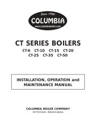
<strong>EMERALD</strong><br />
<strong>SERIES</strong><br />
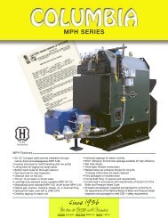
IBR/DOE RATINGS AND DATA<br />
<strong>Boiler</strong> Model No. EM-85 EM-100 EM-3100 EM-110 EM-125 EM-3125 EM-135 EM-150 EM-165 EM-175 EM-200<br />
Firing Rate -- #2 Fuel .85 1.00 1.00 1.10 1.25 1.25 1.35 1.50 1.65 1.75 2.00<br />
Input -- MBTU/Hr. 119 140 140 154 175 175 189 210 231 245 280<br />
DOE Heating Capacity MBTU/Hr. 101 118 119 130 148 146 159 176 183 205 234<br />
Net IBR Rating MBTU/Hr. 88 103 103 113 129 127 138 153 168 178 203<br />
GPM Tankless Coil 3 5 5 5 5 5 5 5 5 5 5<br />
DIMENSIONS (INCHES) EM-85 EM-100 EM-3100 EM-110 EM-125 EM-3125 EM-135 EM-150 EM-165 EM-175 EM-200<br />
A<br />
Casing<br />
C<br />
Length<br />
Height<br />
20"<br />
37-1/4"<br />
20"<br />
37-1/4"<br />
21"<br />
46"<br />
20"<br />
37-1/4"<br />
20"<br />
37-1/4"<br />
21"<br />
46"<br />
21"<br />
46"<br />
21"<br />
46"<br />
21"<br />
46"<br />
21"<br />
46"<br />
21"<br />
46"<br />
D Width 19-1/2" 19-1/2" 21" 19-1/2" 19-1/2" 21" 21" 21" 21" 21" 21"<br />
E Height 34-3/8" 34-3/8" 43-3/8" 34-3/8" 34-3/8" 43-3/8" 43-3/8" 43-3/8" 43-3/8" 43-3/8" 43-3/8"<br />
<strong>Boiler</strong> F Diameter 16-3/4" 16-3/4" 18-3/4" 16-3/4" 16-3/4" 18-3/4" 18-3/4" 18-3/4" 18-3/4" 18-3/4" 18-3/4"<br />
G Base Hgt. 17" 17" 20-1/2" 17" 17" 20-1/2" 20-1/2" 20-1/2" 20-1/2" 20-1/2" 20-1/2"<br />
H Size 6" 6" 6" 6" 6" 6" 8" 8" 8" 8" 8"<br />
Flue I Height 37-1/2" 37-1/2" 47" 37-1/2" 37-1/2" 47" 47" 47" 47" 47" 47"<br />
Outlet J C.L. to Rear 9" 9" 10-1/2" 9" 9" 10-1/2" 10-1/2" 10-1/2" 10-1/2" 10-1/2" 10-1/2"<br />
Size 1-1/4" 1-1/4" 1-1/4" 1-1/4" 1-1/4" 1-1/4" 1-1/4" 1-1/4" 1-1/4" 1-1/4" 1-1/4"<br />
Supply L Height 35-1/4" 35-1/4" 45" 35-1/4" 35-1/4" 45" 45" 45" 45" 45" 45"<br />
Outlet M C.L. to Outlet 9" 9" 8-3/8" 9" 9" 8-3/8" 8-3/8" 8-3/8" 8-3/8" 8-3/8" 8-3/8"<br />
Feed/ Size 1-1/4" 1-1/4" 1-1/4" 1-1/4" 1-1/4" 1-1/4" 1-1/4" 1-1/4" 1-1/4" 1-1/4" 1-1/4"<br />
Drain O Height 19-1/4" 19-1/4" 22-3/4" 19-1/4" 19-1/4" 22-3/4" 22-3/4" 22-3/4" 22-3/4" 22-3/4" 22-3/4"<br />
Size 1-1/4" 1-1/4" 1-1/4" 1-1/4" 1-1/4" 1-1/4" 1-1/4" 1-1/4" 1-1/4" 1-1/4" 1-1/4"<br />
Return Q C.L. to Inlet 20" 20" 20" 20" 20" 20" 20" 20" 20" 20" 20"<br />
Inlet S Height 19" 19" 22-1/2" 19" 19" 22-1/2" 22-1/2" 22-1/2" 22-1/2" 22-1/2" 22-1/2"<br />
Coil Nominal Size 1/2" 1/2" 1/2" 1/2" 1/2" 1/2" 1/2" 1/2" 1/2" 1/2" 1/2"<br />
Conn. U Height 32-1/4" 32-1/4" 42" 32-1/4" 32-1/4" 42" 42" 42" 42" 42" 42"<br />
1<br />
PACKAGED,<br />
HYDRONIC<br />
HEATING BOILERS<br />
COLUMBIA BOILER CO.<br />
OF POTTSTOWN<br />
BOX G, POTTSTOWN, PA 19464 ASME<br />
Construction
Emerald Series Installation and Operators Manual<br />
COLUMBIA<br />
COLUMBIA BOILER CO. OF POTTSTOWN<br />
A Message to: Installer, Serviceman, Homeowner:<br />
Box G, Pottstown, Pennsylvania 19464<br />
Over sixty years of engineering and product development have gone into your new <strong>Columbia</strong> oil fired<br />
boiler. It’s quality and design are unsurpassed. Properly installed and maintained, it will provide many years<br />
of efficient and dependable operation. Please read this Instruction Manual carefully. The information contained<br />
within is designed to help you maintain peak performance from your boiler/burner unit.<br />
A. Installation Instructions<br />
CAUTION:<br />
1. Installer must be a trained, experienced serviceman.<br />
2. Inspect the boiler, jacket and all components to be sure damage has not occurred in shipment. If<br />
damage is evident you must file a claim with the freight carrier immediately.<br />
3. Disconnect power supply before connecting wiring.<br />
4. Refer to local installation codes for oil burning equipment, for recommended installation practice.<br />
5. A complete heat loss calculation is necessary to choose the proper size unit to install. The boiler<br />
should be sized to within 25% of the actual heat loss of the structure.<br />
6. Conduct thorough checkout when installation is complete.<br />
1) Place the boiler on a level non-combustible<br />
floor, preferably raised and as close to the<br />
chimney as possible. The following minimum<br />
clearances must be adhered to during installation<br />
and maintained thereafter to properly<br />
clean, inspect and service your boiler: sides<br />
and back - 6"; front - 24" and vent connector<br />
- 18". Reduced clearance installations must<br />
follow NFPA-31 guidelines.<br />
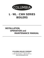
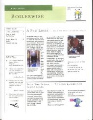
2) For location of piping refer to the installation<br />
drawing in Figure 1. The burner, aquastat<br />
and circulator are wired at the factory. For<br />
power and thermostat (not supplied) wiring<br />
connections see the control manuals provided<br />
along with this manual. For piping and<br />
wiring of other system components see the<br />
manufacturers installation manuals.<br />
3) The tankless water heater may be piped as<br />
shown in Figure 1. A mixing valve, not supplied,<br />
must be used to reduce the water<br />
temperature at kitchen or bathroom taps.<br />
High temperature water for a dishwasher<br />
may be obtained by piping as shown in<br />
2<br />
Figure 1. The nuts that secure the tankless<br />
coil flange should be tightened before the<br />
boiler is filled with water, after initial firing<br />
and once a year during the annual maintenance.<br />
DETERIORATION DUE TO COIL<br />
GASKET LEAKS WILL VOID THE WARRAN-<br />
TY.<br />
3a) This style of boiler is equipped with a built in<br />
“Air Scoop System.” This feature allows<br />
quiet air free operation of your hot water system<br />
by assuring the removal of air pockets<br />
without the installation of Air Scoops to trap<br />
noisy air.<br />
The 1-1/4" supply line or Riser tapping in the<br />
top of the boiler extends approximately 1"<br />
below the top or waterline of the boiler, thus<br />
allowing only air free water to enter the supply<br />
to the heating system. The air trapped in<br />
the top of the boiler is then purged through a<br />
3/4" vent tapping to be released with an (1)<br />
automatic float vent (2) a manual vent or (3)<br />
piped into a conventional type expansion<br />
tank.
Relief valve discharges and drain valve piping<br />
should be piped to a safe place of discharge.<br />
All plugs and water connections<br />
should be checked for leaks upon installation<br />
and annually.<br />
4) Be certain the chimney is clean and free of<br />
obstructions. Connect boiler flue outlet to<br />
chimney using galvanized smoke pipe. The<br />
flue pipe should be pitched upward at least<br />
1/4" per foot of run. Refer to Page 1 in this<br />
manual for proper size flue pipe for your<br />
model boiler. Use only elbows and straight<br />
sections. Tees may be used in a straight section<br />
in conjunction with a barometric draft<br />
regulator; however, they must not be used<br />
for a 90° turn. Each joint should be securely<br />
fastened with sheet metal screws. The flue<br />
pipe must not be inserted beyond the inside<br />
wall of the chimney. Install barometric draft<br />
regulator in the horizontal or vertical section<br />
of the flue pipe.<br />
5) The boiler room must be well ventilated to<br />
allow sufficient make-up air to support combustion.<br />
Lack of adequate combustion air<br />
may result in erratic operation of the burner,<br />
noisy combustion or fuel odors. Remember<br />
your need for outside air will be greatly<br />
increased if you have a vented dryer in the<br />
basement or other venting fans in the home.<br />
<strong>Boiler</strong>s located in confined spaces shall be<br />
provided with two permanent openings, one<br />
near the top and one near the bottom of the<br />
enclosure. Each opening shall have a free<br />
area of not less than one square inch per<br />
1000 BTU per hour input rating of the boiler,<br />
freely communicating with interior areas having<br />
adequate infiltration from the outside.<br />
6) Fill boiler and system with water. Be sure<br />
entire system has been purged of air and the<br />
desired pressure is obtained.<br />
7) Connect burner to oil supply. Refer to fuel<br />
unit manufacturer literature for piping, connections,<br />
lift and tank installation. If such<br />
information is unavailable use the following<br />
guidelines.<br />
FUEL UNITS/FUEL LINES<br />
Fuel supply “level with” or “above” burner: A<br />
single stage fuel unit connected to the fuel supply<br />
with a single supply line is the most common<br />
3<br />
type of installation for these conditions. Manual<br />
venting of the fuel unit is usually required on initial<br />
start-up. Failure to vent air could result in an<br />
air lock/oil starvation condition. (One pipe)<br />
Fuel supply below the level of burner: Use a<br />
single stage fuel unit in lift conditions of up to 10<br />
ft., and a two stage fuel unit when the lift<br />
exceeds 10 ft. Both conditions require the use of<br />
a return line which helps to purge the fuel unit of<br />
air returning it to the fuel tank. The “by-pass”<br />
plug must be inserted into the fuel unit when<br />
installing a return line. (Two pipe)<br />
Fuel line installation: Continuous lengths of<br />
heavy wall copper tubing are recommended and<br />
should be installed under the floor when possible.<br />
Always use flare fittings. Always install fittings in<br />
accessible locations. Never use teflon tape on<br />
any fuel fitting. Use of teflon will void any pump<br />
warranty. Fuel lines should not run against the<br />
appliance or the ceiling joists.<br />
Fuel line valve and filter: Install two high<br />
quality shutoff valve(s) in accessible locations on<br />
the oil supply line. Locate one close to the tank<br />
and the other close to the burner ahead of the filter.<br />
Some filters come with built-in shutoff valves.<br />
Install a generous capacity filter inside the building<br />
between the fuel tank shutoff valve and the<br />
burner locating both the filter and the valve close<br />
to the burner for ease of servicing.<br />
Always use flare fittings.<br />
Never use compression fittings.<br />
IMPORTANT<br />
All oil feed lines to burners must be air tight.<br />
Use only flare fittings when assembling oil lines<br />
since the slightest air leak, caused by loose fittings,<br />
bad gaskets or any other reason, can<br />
cause a foaming oil stream which will cause any<br />
of the following conditions:<br />
a) Intermittent firing, causing safety shutdown<br />
b) Poor starts<br />
c) Smokey starts<br />
d) Continual sooting of boiler and burner<br />
parts including the cad cell<br />
e) Reduced firing rate, inefficient operation<br />
and erratic fire pattern
f) A dangerous combustion condition, allowing<br />
the firebox to fill with a lean mixture<br />
(too much air in the oil stream) which could<br />
cause a delay in ignition of the fuel mixture<br />
until the danger point has been reached.<br />
Suction vacuum must be held to acceptable<br />
limits. The vacuum test is worth the time required<br />
to make it. This problem becomes proportionately<br />
larger with underground tanks. If the following<br />
procedures are followed, burner related problems<br />
will be minimized:<br />
a) Connect vacuum gauge to oil pump.<br />
Suction vacuum must not exceed 10 inches<br />
of mercury for single stage pumps and<br />
15 inches for two stage pumps. It is preferable<br />
to stay below these limitations.<br />
b) When the suction line is tight and properly<br />
installed the pump will hold its vacuum for<br />
a minimum of 60 minutes after shutdown.<br />
c) Installation of a check valve in the suction<br />
line of a two pipe system is advisable<br />
under all circumstances. Be sure the check<br />
valve fittings are airtight.<br />
d) Connect the electric supply to the boiler as<br />
indicated on the wiring diagrams. The<br />
wiring must be installed in accordance with<br />
the National Electrical Code and any other<br />
state and local codes.<br />
C. Operational Sequence<br />
1) <strong>Boiler</strong>s with Tankless Coil - This boiler is<br />
equipped with a combination aquastat control<br />
which has high and low limits to be set<br />
at 180° and 160° respectively by the installer.<br />
When room temperature falls below thermostat<br />
setting, thermostat calls for heat starting<br />
the burner and circulating pump. The burner<br />
and pump continue to operate until room<br />
heating requirements are satisfied (thermostat<br />
setting is reached), or until boiler water<br />
temperature reaches the high limit control<br />
temperature setting. If the high limit control<br />
temperature setting is reached, the burner<br />
shuts off and the circulating pump continues<br />
to operate until the room heating requirements<br />
are satisfied. If the thermostat continues<br />
to call for heat after the boiler water<br />
temperature has dropped below the temperature<br />
setting of the high limit control, the oil<br />
burner will start again, while the circulating<br />
pump will continue to run. The boiler water<br />
4<br />
temperature is normally maintained at 160°F<br />
around the tankless coil by the operating<br />
control so that an abundance of hot water is<br />
available. If the boiler water temperature<br />
should fall below the operating control setting<br />
(160°F) the oil burner will be started<br />
again by that control (and the circulating<br />
pump will be prevented from operating) until<br />
the operating control setting is satisfied. See<br />
control manufacturers literature included in<br />
the data package for detailed wiring, operating<br />
and safety instructions.<br />
2) <strong>Boiler</strong>s Less Tankless Coil - This boiler is<br />
equipped with a high limit aquastat control<br />
which should be set at 180° by the installer.<br />
The oil burner is operated in an identical<br />
sequence as 1), except that the boiler water<br />
temperature need not be maintained at a<br />
160°F low limit setting since there is no<br />
domestic hot water load to protect. See control<br />
manufacturers literature included in the<br />
data package for detailed wiring, operating<br />
and safety instructions.<br />
3) A cadmium sulfide flame scanner (cad cell)<br />
and relay are provided with the oil burner.<br />
The cad cell will stop the oil burner within a<br />
predetermined number of seconds if the fuel<br />
fails to ignite or if the flame goes out during<br />
operation. The oil burner will remain off until<br />
the red reset button on the relay has been<br />
pushed. RESET MUST NEVER BE<br />
PRESSED MORE THAN ONCE DURING A<br />
SINGLE FLAME FAILURE.<br />
D. Start-Up and Check-Out Procedure<br />
CAUTION<br />
Only a trained, experienced serviceman should<br />
attempt the checkout procedure outlined below.<br />
Read the burner manufacturers instructions for<br />
start-up for special instructions and special features<br />
of the burner and control.<br />
1) Combustion test equipment required for<br />
proper burner adjustment:<br />
a) CO2 Analyzer<br />
b) Draft Gauge<br />
c) Oil Pressure Gauge 0-200 PSI<br />
d) Stack Thermometer<br />
e) Smoke Test Gun<br />
f) Vacuum Gauge 0-30 in. of Hg
2) In order to take flue gas samples for combustion<br />
testing a 1/4" hole must be drilled<br />
in the flue pipe between the boiler and the<br />
barometric draft regulator.<br />
3) Open all shut-off valves in the oil supply line<br />
to the burner.<br />
4) Set thermostats substantially above room<br />
temperature.<br />
5) Check electrode settings and readjust air setting<br />
if required. Electrode settings are shown<br />
in the burner manual provided along with this<br />
manual. Burner settings are listed on the<br />
Service Man’s Label attached to the boiler<br />
and on the Burner Unit specifications provided<br />
along with this manual.<br />
6) Install pressure gauge in the 1/8" gauge port<br />
of the oil pump.<br />
7) Turn on switch to start burner. If burner does<br />
not start immediately, you may need to reset<br />
the burner control. See the burner manufac<br />
turers instructions for control and reset<br />
features.<br />
8) On one pipe systems bleed the oil pump as<br />
soon as burner motor starts. To bleed, attach<br />
a length of 1/4" O.D. clear plastic tubing to<br />
the end of the bleed plug and then loosen<br />
plug while holding an empty container under<br />
the tubing to catch all of the expelled oil.<br />
Bleed for at least 15 seconds after the oil<br />
stream is free of all air. If air is still evident in<br />
the bleed line you must check the oil lines,<br />
all fittings, filters and any other connections<br />
for tightness. Kinks in the oil lines will create<br />
undue high vacuum therefore they must be<br />
eliminated. When you are sure all air has<br />
been eliminated then close the bleed valve.<br />
Ignition should be instantaneous following<br />
the closing of this valve. If it is not, proceed<br />
to the trouble shooting guide to determine<br />
why the oil did not ignite.<br />
9) Be sure the oil pump discharge pressure is<br />
adjusted to 140 PSI. If it is not refer to the oil<br />
pump manufacturer’s instruction sheet for<br />
pressure adjustment procedure.<br />
10) FINAL ADJUSTMENTS OF THE BURNER<br />
MUST BE MADE USING PROPER COM-<br />
BUSTION TEST EQUIPMENT. The air supply<br />
should be adjusted by loosening the lock<br />
screw and moving the bulk air band or shut-<br />
5<br />
ter so that the CO2 measured in the stack<br />
ahead of the draft control should be a minimum<br />
of 10% and a maximum of 12%. At the<br />
same time the draft should be adjusted to -<br />
.01"-.02" W.C. over the fire. Install a second<br />
barometric draft control if necessary to<br />
reduce excessive draft. The smoke should<br />
also be checked with a smoke gun and<br />
found to be zero.<br />
11) Check operation of the cad cell relay by<br />
removing one cad cell wire from external terminal<br />
during the flame cycle. The relay<br />
should cut the burner off in approximately 15<br />
to 45 seconds, depending on the control<br />
provided. See the burner manufacturers<br />
manual provided in the data pack.<br />
E. Servicing the <strong>Boiler</strong>/Burner Unit<br />
1) Burner Components: If replacement of burner<br />
parts is necessary, always use parts recommended<br />
by the manufacturer. Specify part<br />
number and description when ordering.<br />
2) Electrode settings are important for reliable<br />
ignition of the oil. Check to be sure the settings<br />
are in accordance with the instructions<br />
provided in the burner manual.<br />
3) Nozzles: The nozzle specifications listed in<br />
the manual are the result of years of exhaustive<br />
engineering testing. ANY NOZZLE<br />
REPLACEMENT SHOULD BE OF THE<br />
EXACT TYPE AS LISTED IN THE SPECIFI-<br />
CATIONS. Use extreme care in handling nozzles<br />
to avoid scratches or dirt that could<br />
cause leaks or affect the oil spray pattern.<br />
4) Fan and blower housing should be kept clean<br />
of dirt and lint. If heating unit is located near<br />
an unvented dryer, special care must be<br />
taken so that lint does not clog the burner air<br />
inlets.<br />
5) Replace the oil filter cartridge annually.<br />
6) Cleaning the <strong>Boiler</strong>: Cleaning should be done<br />
only by a trained, experienced serviceman.<br />
Turn power off to the boiler. To clean the<br />
boiler, remove the flue pipe, jacket top and<br />
flue collector. Remove the baffles then clean<br />
the tubes with a soft 2" flue brush. Reinstall<br />
parts, readjust and clean the burner if<br />
required.”
6<br />
FIGURE 1
Troubleshooting Guide<br />
TROUBLE: BURNER DOES NOT START<br />
SOURCE PROCEDURE CAUSES REMEDY<br />
Power Check boiler disconnect Switch open. Close switch.<br />
and main disconnect switch Tripped breaker or blown fuse Reset breaker or replace fuse<br />
Thermostat Check thermostat settings Thermostat set too low. Turn up thermostat<br />
Thermostat on “off” or “cool” Switch to heat<br />
Jump TT terminals on Thermostat not level Level thermostat<br />
aquastat control. If burner<br />
starts, fault is in the<br />
Open thermostat wires Repair or replace wires<br />
thermostat circuit Loose thermostat connectors Tighten connection<br />
Faulty thermostat Replace thermostat<br />
Circuit Check burner motor overload Burner motor tripped on Press reset button<br />
Resets switch, if equipped overload<br />
Check primary control safety Primary tripped on safety Press reset button<br />
switch.<br />
Aquastat Check limit settings versus Burner off on limit Adjust limit settings<br />
Control boiler water temperature<br />
Check for voltage at L1 and Open safety switch, tripped Close switch, reset breaker<br />
L2 breaker or blown fuse or replace fuse<br />
Jump TT terminals on aquastat No voltage indicates defective Replace control<br />
then check for voltage at<br />
terminals B1 and B2<br />
control<br />
Primary Check for voltage between Aquastat limit control Check limit setting.<br />
Control the black and white leads. No switch open<br />
voltage indicates no power to<br />
the control. Make sure the<br />
the jumper on TT terminals<br />
is installed<br />
Open circuit between limit Repair circuit.<br />
control and primary control<br />
if voltage is present at B1<br />
and B2 of aquastat<br />
Burner Check for voltage burner Pump seized. Turn off power to burner.<br />
motor. Voltage indicates Rotate blower by hand,<br />
power to motor and a fault Blower wheel binding check for excessive drag.<br />
in the burner. Replace fuel unit or blower<br />
wheel.<br />
Burner motor defective Replace burner motor<br />
7
TROUBLE: BURNER STARTS BUT DOES NOT ESTABLISH FLAME<br />
SOURCE PROCEDURE CAUSES REMEDY<br />
Oil Supply Check tank for oil Empty tank. Fill tank.<br />
Check for water in oil tank<br />
using a dip stick coated<br />
with litmus paste<br />
Water in oil tank Strip tank of water<br />
Listen for pump whine. Fuel supply valve closed Open valve<br />
Oil filter plugged Replace filter cartridge<br />
Plugged pump strainer Clean strainer<br />
Restriction in oil line Repair oil line<br />
Open pump bleed port and Air leak in fuel system Repair leak. The use of flare<br />
start burner. Milky oil or no fittings is strongly recomoil<br />
indicates loss of prime mended. Do not use Teflon<br />
tape on oil fittings<br />
Oil Pump Install pressure gauge in port Pump discharge pressure Set pressure at 140 PSI<br />
of fuel pump. Pressure should set too low<br />
be 140 PSI Coupling worn or broken Replace coupling<br />
Pump worn - low pressure<br />
motor overloads<br />
Replace pump<br />
Combustion Check air shutter and Improper air adjustment Adjust air as indicated in<br />
Air air band manual. Set CO 2 to 10%<br />
Requirements min - 12% max with zero<br />
smoke<br />
Ignition Remove and inspect nozzle Incorrect electrode settings Dress up tips and reset<br />
Electrodes line assembly eroded electrode tips electrodes<br />
Carboned and shorted<br />
electrodes<br />
Clean electrodes<br />
Cracked porcelain insulators Replace electrodes<br />
Nozzle Inspect nozzle for plugged Plugged orifice or distributor<br />
orifice and distributor slots or strainer<br />
Inspect nozzle for correct<br />
size and specifications<br />
Incorrect nozzle installed<br />
Ignitor Connect ignitor leads to No spark or weak spark Replace ignitor<br />
line voltage. Listen for spark.<br />
Check that ignitor<br />
terminals are not arcing with<br />
buss bars.<br />
8<br />
Replace nozzle with nozzle<br />
specified in this manual and<br />
on the boiler lower jacket<br />
panel
TROUBLE: BURNER FIRES, BUT THEN FAILS ON SAFETY<br />
SOURCE PROCEDURE CAUSES REMEDY<br />
Cad Cell Check cad cell with ohmmeter. Faulty or dirty cad cell Clean or replace cad cell<br />
If more than 1500 ohms, cad<br />
cell is defective or dirty<br />
Primary See Control Manual Faulty primary control Replace primary control<br />
Control<br />
Poor Fire Inspect flame for stability Wrong nozzle Replace nozzle with<br />
type specified<br />
Improper draft Adjust draft to -.01-.02 W.C.<br />
overfire<br />
Improper air adjustment Adjust air for a CO2 of 10%<br />
min. to 12% max. and zero<br />
smoke<br />
Air in oil supply Repair leaky fittings<br />
Oil Supply If burner loses flame prior Air leak to fuel system Repair leak. The use of<br />
to the primary control Restriction in oil line flare fittings is recommended.<br />
locking out, fault is in the Plugged fuel filter Clear oil line restriction. Refuel<br />
system Plugged pump strainer place filter cartridge. Clean<br />
Cold oil strainer use #1 heating oil<br />
or additive to thin oil<br />
Pump Install pressure gauge in Pump discharge pressure Set pressure at 140 PSI<br />
gauge port of oil pump incorrectly set<br />
Pressure should be 140 PSI Coupling worn or broken Replace coupling<br />
Pump worn Replace pump<br />
Burner Burner motor overloads. Pump or blower Replace blower or pump<br />
Motor Turn off power and rotate overloading motor<br />
blower by hand to check<br />
for excessive drag Faulty motor Replace motor<br />
TROUBLE: HIGH NET STACK TEMPERATURES<br />
SOURCE PROCEDURE CAUSES REMEDY<br />
Nozzle Inspect nozzle for correct Incorrect nozzle Replace nozzle with nozzle<br />
size and type specified<br />
Check pump pressure with Nozzle overfiring due to Reduce pump pressure to<br />
pump gauge high pump pressure 140 PSI<br />
Heat Check heat exchanger surfaces Heat exchanger fouled Clean heat exchanger<br />
Exchanger for soot or scale fouling<br />
9
TROUBLE: BURNER FIRES BUT PULSATES<br />
SOURCE PROCEDURE CAUSES REMEDY<br />
Draft Take a draft reading. Draft Insufficient draft Increase draft setting. Be<br />
should be -.01"-.02" W.C. sure chimney is clean and<br />
overfire meets the minimum size<br />
requirements.<br />
Excessive draft Reduce draft settings. Install<br />
second draft regulator if<br />
necessary<br />
Draft Inspect draft regulator for Improper installation Move draft regulator to<br />
Regulator correct location correct location<br />
Combustion Inspect installation for Insufficient amount of make-up Provide openings that freely<br />
Air adequate incoming make-up<br />
air<br />
air in boiler room communicate with outside.<br />
Adjust combustion air<br />
and take a CO2 reading<br />
Improper air intake<br />
adjustment<br />
Adjust CO2 level to 10% min.<br />
12% max. and zero smoke<br />
Oil Supply Bleed pump and inspect for Air leak in fuel system Repair air leak<br />
air Use flare fittings only<br />
Pump Install pressure gauge in Pump discharge pressure Set pressure at 140 PSI<br />
Pressure port of oil pump. Pressure incorrectly set<br />
should be 140 PSI<br />
Coupling worn or broken Replace coupling<br />
Nozzle Inspect nozzle for plugged Plugged orifice or distributor Replace nozzle with<br />
orifice and distributor slots correct nozzle as specified<br />
Plugged nozzle strainer<br />
TROUBLE: TOO MUCH HEAT<br />
SOURCE PROCEDURE CAUSES REMEDY<br />
Circulator Check to see if operating Circulator does not stop Repair operating control<br />
control is working properly running<br />
Thermostat Check thermostat settings Thermostat set too high Reset thermostat<br />
and calibration Thermostat defective Replace thermostat.<br />
Thermostat out of calibration Recalibrate.<br />
Flow or Check to see if flow valve/ Flow valve/zone valve dirty Replace zone valve<br />
Zone Valve zone valve is operating and stuck Replace flow valve<br />
properly<br />
10
TROUBLE: INSUFFICIENT HEAT<br />
SOURCE PROCEDURE CAUSES REMEDY<br />
Circulator Check if circulator is Pump binding Replace pump<br />
operational. Circulator motor burned out Replace circulator motor<br />
Wiring from operating<br />
control defective<br />
Repair wiring<br />
Operating control defective Repair or replace operating<br />
control<br />
Thermostat Check thermostat settings Settings too low Increase setting<br />
Check thermostat location Bad location due to heat Move thermostat to a<br />
build up better location<br />
Check thermostat calibration Out of calibration Recalibrate<br />
Flow Valve/ Check flow valve/zone valve Flow valve/zone valve not Clean or replace flow<br />
Zone Valve for sticking in partially opening fully valve/zone valve<br />
closed position<br />
Radiation Check for air in radiators Radiators airbound Bleed radiators<br />
Check to see if radiators are<br />
sized properly<br />
Radiators inadequate Install adequate radiation<br />
Tankless Check usage of domestic Demand too large Install flow regulator<br />
Coil hot water Additional boiler capacity<br />
required<br />
Heat Check heat exchanger for soot Insufficient heat transfer Clean heat exchanger<br />
Exchanger or scale accumulation<br />
Burner Check pump pressure with Insufficient pump pressure Increase pressure to 140 PSI<br />
pressure gauge<br />
Nozzle Check nozzle for size and<br />
spray angle<br />
Wrong nozzle installed Install specified nozzle<br />
Check nozzle for plugged Nozzle underfiring due to Replace nozzle<br />
orifice, scoured surface defective nozzle<br />
TROUBLE: INSUFFICIENT DOMESTIC HOT WATER<br />
SOURCE PROCEDURE CAUSES REMEDY<br />
Tankless Coil Analyze capacity vs. usage Insufficient coil capacity Install larger coil<br />
Check coil for fouling Hard water scaling Install soft water system<br />
Clean coil<br />
Operating Check operating control Setting too low Set operating control<br />
Control setting low limit to 160°F<br />
Heat Inspect coils for fouled sur- Flow restriction Remove restriction<br />
Exchanger faces and/or flow restrictions<br />
Fouled surfaces or heat Clean heat exchanger<br />
exchanger surfaces<br />
11
ELECTRICAL DIAGRAM FOR EM <strong>SERIES</strong> BOILERS<br />
TO CONNECT BURNER TO AQUASTAT<br />
(APPLIES TO CARLIN CHIMNEY VENT AND RIELLO CHIMNEY VENT BURNERS)<br />
12
ELECTRICAL DIAGRAM FOR EM <strong>SERIES</strong> BOILERS<br />
TO CONNECT BURNER TO AQUASTAT<br />
(APPLIES TO BECKETT CHIMNEY VENT BURNERS)<br />
13
1. Date<br />
2. Model Number<br />
3. Firing Rate<br />
4. Pump Pressure*<br />
5. CO2<br />
6. “0” Smoke<br />
7. Gross Stack°F<br />
8. Draft Over Fire<br />
9. Replaced Filter Yes/No<br />
10. Replaced Nozzle Yes/No<br />
11. Clean Pump Filter Yes/No<br />
12. Inspect Coil Gasket<br />
13. Check for Leaks @ plugs/fittings<br />
14. Brush Clean Flue Tube Passages<br />
15. Vacuum Chamber/Flue Tubes<br />
16. Clean Blower Wheel<br />
17. Check/Set Electrodes<br />
BURNER SERVICE SET-UP RECORDS<br />
1 2 3 4 5<br />
14
1. Date<br />
2. Model Number<br />
3. Firing Rate<br />
4. Pump Pressure*<br />
5. CO2<br />
6. “0” Smoke<br />
7. Gross Stack°F<br />
8. Draft Over Fire<br />
9. Replaced Filter Yes/No<br />
10. Replaced Nozzle Yes/No<br />
11. Clean Pump Filter Yes/No<br />
12. Inspect Coil Gasket<br />
13. Check for Leaks @ plugs/fittings<br />
14. Brush Clean Flue Tube Passages<br />
15. Vacuum Chamber/Flue Tubes<br />
16. Clean Blower Wheel<br />
17. Check/Set Electrodes<br />
BURNER SERVICE SET-UP RECORDS<br />
6 7 8 9 10<br />
15
<strong>Columbia</strong> Emerald<br />
<strong>Boiler</strong>/Burner<br />
Unit Specifications<br />
BOILER/BURNER UNIT SPECIFICATIONS - BECKETT AFG<br />
Pump Burner Delavan Approximate Air Setting<br />
<strong>Boiler</strong> Model Pressure PSI Hd. Nozzle Shutter Band<br />
EM - 85 140 F-3 .65 80°B 8 0<br />
EM-100 140 F-3 .75 80°B 10 0<br />
EM-3100 140 F-3 .85 80°B 10 0<br />
EM-110 140 F-6 .85 80°B 10 0<br />
EM-3125 140 F-6 1.00 80°B 10 2<br />
EM-125 140 F-6 1.00 80°B 10 2<br />
EM-135 140 F-6 1.10 80°A 10 2<br />
EM-150 140 F-12 1.25 80°A 9 0<br />
EM-165 140 F-12 1.35 80°A 10 0<br />
EM-175 140 F-12 1.50 80°A 10 1<br />
EM-200 140 F-22 1.65 80°A 10 2<br />
BOILER/BURNER UNIT SPECIFICATIONS - RIELLO 5F BURNER<br />
Pump Delavan Approximate Air Setting<br />
<strong>Boiler</strong> Model Pressure PSI Nozzle Band<br />
EM - 85 150 .65 60°A 1.75<br />
EM-100 150 .75 60°A 1.75<br />
EM-110 150 .85 60°A 2.25<br />
EM-125 150 1.00 60°A 2.75<br />
EM-135 150 1.10 80°A 3.25<br />
EM-150 150 1.25 80°A 3.8<br />
EM-165 150 1.35 80°A 2.0<br />
EM-175 150 1.50 80°A 2.8<br />
EM-200 150 1.65 80°B 2.75<br />
BOILER/BURNER UNIT SPECIFICATIONS - CARLIN EZ-1 BURNER<br />
Pump Delavan Approximate Air Setting<br />
<strong>Boiler</strong> Model Pressure PSI Nozzle Band<br />
EM - 85 140 .65 70°A .65<br />
EM-100 140 .75 70°A .65<br />
EM-110 140 .85 70°A .75<br />
EM-125 140 1.00 60°B .85<br />
EM-135 140 1.10 60°B .90<br />
EM-150 140 1.25 60°B 1.25<br />
EM-165 140 1.35 60°B 1.35<br />
EM-175 140 1.50 70°A 2.00<br />
EM-200 140 1.65 70°A 2.00<br />
Notice: All settings are approximate. Check the Installer Serviceman Label on the boiler for updates and use instruments<br />
to make final settings in accordance with the procedure in this manual.<br />
16
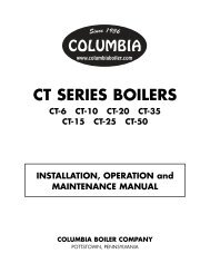
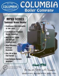
OIL BURNER<br />
BECKETT AFG BURNER (PART NO. 540120)<br />
CARLIN EZ-1 BURNER (PART NO. 542210)<br />
RIELLO F-5 BURNER (PART NO. 541152)<br />
1. KNOCKDOWN BOILERS SUPPLIED WITH THREE (3) PIECE<br />
SIDE/REAR JACKET.<br />
2. BASE ASSEMBLY FOR UNITS PRODUCED PRIOR TO 1999<br />
CONSISTING OF BASE, CHAMBER WRAPPER, FRONT<br />
PANEL, PEEP SIGHT, CHAMBER SUPPORT BLOCK AND FIRE<br />
CHAMBER (PART NO. 790416).<br />
3. BASE ASSEMBLY FOR UNITS PRODUCED AFTER 1999<br />
CONSISTING OF BASE, CHAMBER WRAPPER, FRONT<br />
PANEL, PEEP SIGHT, CHAMBER SUPPORT BLOCK AND FIRE<br />
CHAMBER (PART NO. 790415).<br />
CBC P/N 595850<br />
10/08 - 500<br />
NOTES:<br />
CC-7821