Optimize Powder Processing - Chemical Processing
Optimize Powder Processing - Chemical Processing
Optimize Powder Processing - Chemical Processing

Create successful ePaper yourself
Turn your PDF publications into a flip-book with our unique Google optimized e-Paper software.
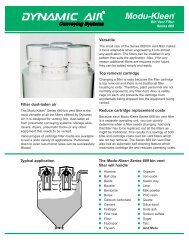
Ad IndexSchenck Process 2www.accuratefeeders.comMettler Toledo 5us.mt.comKuriyama of America, Inc. 7www.kuriyama.comHapman 10www.hapman.comVac-u-Max 13www.vac-u-max.comFike 17www.fike.comFederal Equipment Company 22www.fedequip.comRembe, Inc. 24www.rembe.usHouston 26www.houstonvibrator.comSystem Discharges Bulk BagsBulk bag unloader is designed for pneumatic conveying systemsThe Bulk Bag unloader from VAC-U-MAX provides a clean and efficient way todischarge the entire contents of a bulk bag. It’s specifically designed for semi to nonfree-flowingpowders. VAC-U-MAX Bulk Bag Dischargers use our proprietary pneumaticallyoperated massage paddles, operator access door for a complete sealed system,dust collection port, heavy-duty tubular frame, motorized hoist and trolley, and screwdischarger for controlled metering of powders into the convey line or process.For more information visit www.vac-u-max.com or call 800-VAC-U-MAX (822-8629).Vac-u-maxwww.vac-u-max.com4
CURRENT CONFIGURATIONFigure 3. Viewing operation as consisting of two separate procedures led to use of two control valves.the weak brine used to cool a byproduct gas stream,which in turn altered the temperature of the byproductgas, prompting the byproduct gas compressors totrip offline.Alternating the salt slurry between tanks was aproblem, too. The salt level in the tanks decreased asthe weak brine dissolved it, so the brine leaving thetanks became too weak, reducing reactor efficiency.In addition, operators had to invest a full shift twice aweek to clean the salt recovery equipment.Although the problems seemed endless, extensivediscussions among the team of internal engineers,the consulting process engineers and key operationspersonnel produced a simple solution: combine theparallel operations to create one continuous process.The process includes a new brine saturation tankthat feeds both reactor sets and a single new feed neutralizationtank fitted with two outlets, and combinesthe brine-saturation and excess-salt-dissolver operations(Figure 2). The solution also incorporates newspecifications for active cathodic corrosion protectionof the brine saturation feed tank — it has thickerwalls and welds protected with a trowel-applied lining.The salt-slurry cyclone separator, splitter box andexcess-salt dissolver tank all were eliminated.The changes have provided a number of substantialbenefits:• elimination of corrosion as verified by subsequentcheckups over time;• increased byproduct gas recovery to 93% from85%;• improved reactor efficiency due to nearly100%-strong brine availability;• decreased operating complexity; and• reduced maintenance because of the significantlylower quantity of equipment.This solution illustrates that sometimes it’s necessaryto go beyond thinking about fixing the problemto thinking about a more straightforward way to dothe process.SIMPLIFIED CONTROLUnnecessary complexity also can afflict controlsystems. For example, when working up a designfor additional processing capacity for a reactoreffluent gas stream, the consulting process engineersnoticed opportunities to simplify the existingcontrol system.Typically, the system for recovering byproductfrom the reactor was viewed as having two separate9
PROPOSED CONTROL SCHEMEFigure 4. Regulating pressure via a single control valve enables use of a slightly smaller compressor and affords better control.procedures, reaction and compression, and wasdesigned with separate control valves for each. Asbyproduct from the reactor made its way to the compressorsthat processed the end product, it first wascycled through an intermediate recovery unit where adedicated valve controlled the pressure of the reactor.Downstream of that valve, another control valve onthe compressor’s discharge recycle line regulated compressorsuction pressure. In this configuration, thepressure was controlled on both sides of the controlvalve (Figure 3).Viewing the two processes as one continuous systemled to a straightforward solution — eliminatingthe upstream valve and controlling pressure only withone properly sized valve in the compressor’s dischargerecycle line (Figure 4). This also allowed for a slightlysmaller compressor that optimally handles a highersuction pressure and better controls the volume flowof the compressor feed stream. The change supporteda continuous flow at a rate that met the increasedcapacity requirement.COMMON CONCERNSProcess simplification means change — and thatcan raise objections. People resist because they’reinvested in the existing process, worry about thereliability of the new configuration, or even fear joblosses.Engineers experienced in simplification don’tdwell on criticizing the existing process, but insteadfocus on the benefits of the improvements and, whenpossible, how to implement them in a phased way ifthat better suits the situation.A question that often arises during streamliningefforts is: “What if the line breaks down, then what?”When the solution stems from a holistic team-basedapproach, the ability to see the sound technical basisof simplification surfaces more readily. The notionthat separate processes creating daily operationalproblems and frequent maintenance are more reliablethan a single continuous process becomes moot, especiallywhen engineers have experience with streamliningand can cite successful implementations.Converting the brine feed process to a straightforwardone required fewer pieces of equipment,increased the efficiency of the brine saturation process,and eliminated controller upsets and byproductcompressor trips. The higher byproduct recovery rateboosted the profit on its sale.Similarly, eliminating the controller in the reactorprocess allowed for a smaller more-efficient compressorto regulate the feed stream volume in such a way11
Suppress Explosions for Process ProtectionA properly designed and engineered suppression system offers many advantagesBy Jef Snoeys, Fike Corp.Consider a variety of reasons for applyingexplosion protection: OSHA and EPA complianceissues, corporate safety directives, pressure frominsurance companies, process changes, technologyimprovements and more. But the most importantreason is a bit more basic: doing the right thing toprovide for the safety of employees and the facilityin which they work.For years, explosion venting has been the primarystrategy for explosion protection. However,improved protection technologies, increasingpublic awareness and stiffer regulations fromEPA, OSHA and NFPA all point to consideringalternative, or additional, protection strategiesand systems.Explosion suppression is a technique wherebycombustion of an explosive atmosphere in aclosed, or essentially closed volume, is detectedand arrested during incipient stages, therebyrestricting development of damaging pressures.Explosion suppression offers many advantagesas a protection method. First, suppression stopsthe deflagration before developing pressure candamage the process equipment. In addition, itcontrols any ensuing fire and reduces the propagationof the flame front to other process equipment.Because explosion suppression doesn’t vent flameor other material, it’s the solution of choice whentoxic materials are being handled, equipment islocated indoors, or venting exposes personnel todischarge of pressure and flame. Explosion suppressionsystems utilize electrical and mechanicalcomponents that can be adapted easily to mostprocesses and are maintained in an active conditionwith continuous electrical supervision ofcomponents.Using Explosion Suppression to Protect Your ProcessA properly designed and engineered explosion suppression system offers a variety of distinct advantages:• Extinguishes the flame within the equipment, preventing fire damage• Helps prevent pressure piling and secondary explosions with interconnected equipment (especially when used inconjunction with explosion isolation systems)• Complies with NFPA regulation barring venting of explosions indoors. (Explosion vents must be discharged to a safelocation. Indoor applications are difficult to vent — even with discharge ducts.)• Retains toxic or valuable materials within the process equipment• Integrates with the process controls to enable other protection devices, process shutdown and remote annunciation devices• Suppresses Class ST III dust hazards, the highest level of industrial explosion• Greater latitude in protection strategies, and process operations14
Nozzles. To ensure a uniform suppressantdistribution in the vessel to be protected, dispersionnozzles, fitted with protected caps aremounted to extend into the vessel (see Figure7). Traditional suppression systems used “pepperpot”style nozzles which aren’t very suitablefor powder-based suppression systems. Instead,nozzles with large openings in the top and sideshave been developed to ensure a hemispherical,fast and uniform distribution of the suppressant(see Figure 8).Many processes, particularly in the food andpharmaceutical industries, require the use ofhardware that prevents the buildup of material.This provides optimum processing and easiercleaning of the equipment (CIP). To addressthese needs, telescopic nozzle arrangements havebeen developed which are flush mounted andtypically use a silicone, Teflon or stainless steelnozzle cover. The nozzle functions by movingfrom the flush position to a position inside theprotected area when the system is activated.Nozzles<strong>Powder</strong> DistributionFigure 7. Dispersion nozzles fitted with protected caps are mounted to extendinto the vessel to ensure uniform suppressant distribution.Figure 8. Hemispherical suppressant powder distribution is attained when usingnozzles with large openings in the top and sides.19
LARGE-SCALE TESTINGUnderstanding the explosibility characteristics of aparticular process media, or other explosion hazard,is typically the first step toward obtaining effectiveprotection. However, large-scale testing is requiredto validate the interaction between the dynamics ofexplosion propagation and the suppression systemhardware to achieve TSP within the strength limitationsof the equipment.Large-scale tests are conducted with test chambervolumes that are similar to the volumes of industrialequipment (Figure 9). Explosion chambers withvolumes from 0.5 to 250m 3 have been used to validatelarge-volume suppression. In these chambers, explosionswith K STvalues of up to 550 bar.m/s are generatedand the explosion suppression system is allowed toreact independently to these explosions. Experimentalparameters of importance are volume, K ST, Pact andsize and number of suppressant discharge containersused. Figure 10 shows a dataset obtained by varyingthe number of containers used to suppress a K ST300bar.m/s hazard in a 25 m 3 vessel.From the experimental data, the minimum numberof HRD-suppressors, N S, required to effectivelysuppress an explosion of a defined explosion violenceusing the ISO method of dust distribution in a givenvolume, V, can be determined using following equation:N S= N o.V 2/3 .When selecting an explosion suppression supplier,check the availability of efficiency numbers toensure that large-scale-suppression testing has beenperformed and that the protection requirements aremet. It’s advised to work with your selected explosionprotection provider to relate relevant explosionand process characteristics to the suppression systemsperformance. It’s common practice to use CAD softwaretools to solve complex problems and design theoptimum suppression system.Large-Scale TestsFigure 9. A 250-m 3 explosion test chamber fitted with Fike 50 L suppressors (whitecolored containers) is used for large-scale testing.Reduced PressureFigure 10. Containers used to suppress a K ST300 bar.m/s hazard in a 25 m 3 vessel.20
Explosion IsolationExplosion isolation systems are designed to work in conjunction with both venting and suppression protection methods, bypreventing the deflagration from reaching other areas through interconnected process pipes or ducts — placing the connectedequipment and facilities at risk for secondary explosions. These secondary explosions are often the cause of the mostsevere damage and loss of life. Explosion isolation systems prevent the propagation of flame through the use of fast-actingvalves or chemical barriers, effectively eliminating secondary explosions.Mechanical explosion isolation involves the use of uniquely designed mechanical valves which provide an actual physicalbarrier to prevent the spread of an explosion through connecting pipework.<strong>Chemical</strong> explosion isolation is achieved through a rapid discharge of a chemical explosion suppressant to prevent the flamefrom continuing through to other areas of a process system. An explosion detector initiates the release of the extinguishing agentwhen it detects a deflagration pressure or flame front, preventing the propagation of flame and burning materials.Regardless of other protection measures, explosions must be prevented from propagating to other locations within the facility.Experimental DataFigure 11. Values of the constants N ofor the Fike explosion suppression system using HRD-suppressors with 4-in. (101.4-mm) and6-in. (152.4-mm) outlets (dry powder suppressant; Ps = 62 bar; V = 1-1000m³).SAFETY IN SPEEDWith any explosion protection system, speedis paramount. Detection, control and releasingfunctions must be completed within a fewmilliseconds. With proper system design anda response in milliseconds, a suppressed explosionis limited to a typical pressure increase inthe range of 3 to 7 PSIG. The reduced pressurelimit brought about by suppression is very shortin duration and minimizes equipment damagewhile optimizing personnel safety. Additionaladvantages are seen when toxic materials arebeing handled, equipment is located indoors, orventing exposes personnel to discharge of pressureand flame. However, the increased cost overa passive (venting) solution, is incremental andmaintenance is required to ensure overall systemreadiness and reliability throughout the lifecycleof the suppression system.JEF SNOEYS, MSc, has been with Fike Corporation since 1993and is currently the Manager of the Explosion Protection TechnologyGroup. Jef has carried out consultancy work worldwide in dustexplosion protection, notably in the pharmaceutical, food andchemical industries, providing risk assessment reports and safetyaudits. He can be reached at jef.snoeys@fike.com.BibliographyInstrument and Automation Engineers’ Handbook (IAEH). 4th EditionChatrathi, K. ; Going, J. Dust Deflagration Extinction, AIChE 2000Chatrathi, K. ; Safety and Technology News, Fike, Volume 7 issue21
THE SOURCE ... for Pharmaceutical, <strong>Chemical</strong>, Plastics, and Related Process Equipment.(877) 536-1538 orwww.fedequip.comPharmaceutical and <strong>Chemical</strong> Manufacturing EquipmentFederal Equipment Company has more than 50-years experience in the processing equipment industry,providing quality used equipment, outstanding service, and competitive prices to chemical, pharmaceutical,plastics, and related process industries. Major markets include API, speciality and fine chemical, bulk chemical,and pharmaceutical and biopharmaceutical manufacturing, including solid dose, liquids, powders, aseptic filling,and packaging.In addition to thousands of pieces of equipment in stock and ready to ship, Federal Equipment offers specializedservices including the liquidation and auction of process lines and manufacturing facilities, equipment appraisals,rigging, testing, and auction services, as well as managing the negotiated liquidation of surplus equipment.Federal Equipment is your source for Pfizer process and packaging equipment. Go tofedequip.com and check out the latest additions to our inventory from Pfizer sitesaround the world.Buy the best, from the best!Your Source for Pfizer Surplus Equipment• Blister Lines• Bottling Lines• Capsule Fillers• Centrifuges• Coating Pans• Dryers• Filters• Fluid Bed Dryers• Fluid Bed Granulators• High Shear Mixers• Lab Equipment• Mixers• Tablet Presses• Tanks• Roller Compactors39” APV Pilot Spray Dryer, S/S10 Liter GEA Collette NV High Shear Mixer,UltimaGral 10, 316 S/SContact Us At 1.800.652.2466 or by Email at pharmaceutical@fedequip.com to get a Fast Quote.View Our Entire Inventory Online at www.fedequip.com8200 Bessemer Ave. • Cleveland, Ohio 44127 • T (800) 652-2466www.fedequip.com • pharmaceutical@fedequip.com22
Measure with ConfidenceThe correct weighing system and a proper maintenance schedule can ensure accuracyBy Steven Wise, Mettler-ToledoFrom measuring raw ingredients to verifyingthe final product packaging, industrial scalesplay a critical role in the manufacturing process.But how do you know that the scale used in yourprocess is the correct one and what the propermaintenance schedule is for your application,applicable regulations and location? The GoodWeighing Practice (GWP) methodology fromMettler-Toledo, a global manufacturer of precisioninstruments for use in industrial applications,can help answer these questions.Measurement Uncertainty in WeighingGWP is based on the concept of measurement uncertainty.Any measuring device, whether it’s a ruler,a speedometer, or a scale, has some measurement uncertaintyassociated with it. Uncertainty means thatno measurement is perfect, but is always distorted byrandom errors and unknown systematic errors. It’sexpressed as an error associated with the weight (10lbs ± 0.001 lbs).As with any measurement device, uncertaintydirectly affects the accuracy of the reported value in aweighing system (see Figure 1). The error is less significantwhen you are weighing something large relativeto the capacity of the scale. However, as you attemptto weigh something smaller and smaller on the scale,the relative uncertainty becomes more and moresignificant. At some point, the relative uncertainty isso significant that you lose confidence in the reportedweight value.For example, suppose you have a scale that’s accurateto plus or minus 1 gram. At 10,000 grams (10kg), this uncertainty represents one hundredth of onepercent (0.01%) of the weight. In many situations,that uncertainty is small enough that it won’t affectquality. Now suppose you’re weighing a 10 gramsample on this scale with an uncertainty ± 1 gram.Now the uncertainty represents a full 10% of the reportedweight. Your actual sample may be 10% largeror 10% smaller than what this scale is reporting justdue to the uncertainty.In the same way that you can’t use a standard 12-inch ruler to measure the width of a human hair, youcannot use a truck scale to weigh a feather accurately.Factors Affecting UncertaintyThe measurement uncertainty of a weighing systemis a combination of many factors. The readability,sensitivity, repeatability, non-linearity and eccentricityof the scale are all factors affecting measurementuncertainty and are associated with the scale design.The scale manufacturer can calculate the uncertaintyof the weighing system associated with these factors.However, the environment in which the scale isused also impacts the uncertainty of the weighing system.The environment is unique to every scale installationand cannot be calculated at the time the scale ismanufactured. Significant impacts from the environmenton weighing uncertainty can be attributed towind, dirt, dust, temperature fluctuations, vibrationsand operator errors among other factors. The only wayto calculate the measurement uncertainty associatedwith the environment is to test the scale installedin the environment using the appropriate tools andmethods.23
U [kg] = U0 + Constant x WeightAbsolute measurement uncertainty [kg]Uncertainty U [kg or. %]Process tolerance (%)Relative measurement uncertainty (%)Weight [kg]MaxFigure 1. Relative uncertainty increases dramatically as the weight measured decreases.Impacts of UncertaintyThe accuracy of a scale directly affects the qualityof the final product. Using the correct scale for theapplication and maintaining it properly will ensure aproduct’s quality.The GWP methodology provides the necessaryinformation to make decisions about your weighingsystem. First, when considering a new scale applicationGWP will identify the suitable scale (or scales)based on the items being measured and the requiredaccuracy.Second, GWP considers the suitability ofthe scale installed in the actual application andenvironment. By testing the scale in place, theweighing process is certified to meet the finalproduct quality requirements and the scales areproven to be fit for their intended use. Verificationwill also identify weighing installations that maynot be suited for the particular application andcould affect quality.Finally, testing in place will determine the propermaintenance schedule for the weighing applicationto help ensure the accuracy of the scale throughoutits lifetime. Following this evaluation, it’s common tofind scales being maintained more often than necessary.The result is extra downtime and cost that isn’tneeded to ensure accuracy. In other situations, scalesare being under-maintained resulting in questionableresults over time.The scale is a key component in many operations.Be sure that you have the correct weighing system foryour application and the best maintenance scheduleto ensure a long life of accurate results.STEVEN WISE is Segment Market Manager for Mettler-Toledo.He can be reached at Steve.Wise@mt.com.25