HX Series Remote Condenser Site Preparation and ... - Chiller City
HX Series Remote Condenser Site Preparation and ... - Chiller City
HX Series Remote Condenser Site Preparation and ... - Chiller City

Create successful ePaper yourself
Turn your PDF publications into a flip-book with our unique Google optimized e-Paper software.
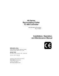
<strong>HX</strong> <strong>Series</strong>Recirculating <strong>Chiller</strong><strong>Remote</strong> <strong>Condenser</strong>NESLAB Manual P/N 002001Rev. 07/15/98<strong>Site</strong> <strong>Preparation</strong><strong>and</strong> Installation ManualNESLAB onlineProduct Service Information, ApplicationsNotes, MSDS Forms, e-mail.Call our bulletin board system(603)427-2490Contact us for free access software.Voice Info: (800) 4-NESLABComments on this manual can be sent to:NESLAB@neslabinstruments.comor visit our Web page at:http://www.neslabinc.com
<strong>HX</strong> <strong>Series</strong> Recirculating <strong>Chiller</strong> <strong>Remote</strong> <strong>Condenser</strong> <strong>Site</strong><strong>Preparation</strong> <strong>and</strong> Installation ManualPREFACETable of ContentsCompliance ............................................................................................ 2Unpacking .............................................................................................. 2Installation Assistance............................................................................ 2SECTION IGeneral InformationSECTION IISafetySECTION IIIInstallationObjective................................................................................................. 3Overview of Responsibilities .................................................................... 3Warnings ................................................................................................ 5Accessibility ........................................................................................... 5<strong>Site</strong>......................................................................................................... 7Electrical Requirements .......................................................................... 13Refrigeration Requirements ..................................................................... 14Inspections ............................................................................................. 18Refrigeration Diagram <strong>HX</strong>-150 ................................................................. 19Refrigeration Diagram <strong>HX</strong>-200 through <strong>HX</strong>-900 ......................................... 20SECTION IVWarranty ............................................................................................................... 21- 1 -
CompliancePrefaceThe CE label on the rear of the unit identifies products tested <strong>and</strong> found to bein compliance with the requirements defined in the EMC st<strong>and</strong>ards defined by89/336/EEC. The testing has demonstrated compliance with the followingst<strong>and</strong>ards:EMC:EN 55011, Class A Verification Industrial, Scientific <strong>and</strong> Medical EmissionsIEC 801-2: 1991 Electro-Static DischargeIEC 801-3: 1988 Radiated Electromagnetic FieldIEC 801-4: 1988 Conducted Electrical Fast Transient/BurstFor any additional information refer to the Letter of Compliance that shippedwith the unit.UnpackingUnless it is otherwise impractical because of doorway or passage constraints,do not remove the remote condenser or the base unit from theirshipping crates (or cartons) before the components are in their final location<strong>and</strong> are ready to be installed.Retain all cartons <strong>and</strong> packing material until the unit is operated <strong>and</strong> found tobe in good condition. If the unit shows external or internal damage, or does notoperate properly, contact the transportation company <strong>and</strong> file a damage claim.Under ICC regulations, this is your responsibility.InstallationAssistanceNESLAB is committed to providing complete technical support throughoutthe installation process. We underst<strong>and</strong> that the ability to complete aninstallation project on schedule is a large factor in the success of a remotecondenser installation. We will cooperate fully with the customer to ensurethat the installation proceeds smoothly <strong>and</strong> that you receive the prompt,courteous service <strong>and</strong> high quality product that you deserve.This manual addresses the major considerations involved in site preparation<strong>and</strong> component installation. However, due to the large number of optionsavailable with our recirculating chillers <strong>and</strong> the many variables involved ininstalling a remote condenser, additional information may be necessary. If youhave questions concerning the installation of your components, the informationin this manual, or the installation process in general, please contact our SalesDepartment for assistance.- 2 -
ObjectiveSection I General InformationThis manual is intended as a guide to assist the NESLAB customer inselecting <strong>and</strong> preparing a site, <strong>and</strong> installing a remote condenser to an <strong>HX</strong><strong>Series</strong> Recirculating <strong>Chiller</strong>. The focus of the manual is on the installation ofthe remote condenser in conjunction with the base unit (chiller).This manual is not intended as a guide for installing the base unit to theinstrument being cooled; this information is contained in the operation manual<strong>and</strong> is shipped with the base unit. Operation <strong>and</strong> maintenance instructions forthe remote condenser are also included in the chiller’s operation manual.Overviewof ResponsibilitiesIn an effort to make the installation proceed as smoothly as possible, as wellas, specify contractual responsibilities, the following overview is provided. Theoverview outlines both NESLAB’s <strong>and</strong> your responsibilities during <strong>and</strong> afterthe installation process. Exceptions or deviations from these responsibilitiesmust be approved, in writing, by NESLAB prior to installation.NESLAB provides the base unit with a full charge of refrigerant, the remotecondenser, <strong>and</strong> complete specifications on the installation of the remotecondenser <strong>and</strong> its connection to the base unit.The complete installation specifications are provided in two ways: the <strong>Site</strong><strong>Preparation</strong> <strong>and</strong> Installation Manual; <strong>and</strong> the technical support provided byNESLAB’s Sales, Service, <strong>and</strong> Engineering Departments.After installation, an on-site inspection <strong>and</strong> certification by a NESLABservice technician is required to validate the warranty on the refrigerationsystem components.The on-site inspection includes a complete inspection for conformance withthe requirements outlined in this manual, evacuating the refrigerant linesbetween the condenser <strong>and</strong> the base unit, performing the initial start up of theunit, <strong>and</strong> providing any additional education requested concerning the operationor maintenance of the system.You are responsible for providing all electrical connections <strong>and</strong> the propervoltage source, all refrigeration plumbing between the base unit <strong>and</strong> theremote condenser (including piping, valves, adequate venting, <strong>and</strong> a completeleak check of all tubes <strong>and</strong> joints), <strong>and</strong> all site requirements (serviceaccess, concrete pads, mounting hardware, etc.).The corresponding chapters in this manual describe each of these requirements.- 3 -
In addition, you are responsible for obtaining all licenses <strong>and</strong> approvalsrequired for the installation, <strong>and</strong> installing the unit in compliance with allapplicable construction codes.The base unit <strong>and</strong> remote condenser have a one-year warranty againstdefective parts <strong>and</strong> workmanship from date of written approval certifying theinstallation. The warranty does not cover customer-installed parts or theworkmanship of their installation. See the back page for complete details.For long term reliable operation, the system must be maintained on a regularbasis (see base unit operator’s manual for service <strong>and</strong> maintenance procedures).If customer-provided care is not practical, contact the Service Managerat our Headquarters in New Hampshire for complete on-site servicecontract information. Failure to properly maintain the system can causedamage <strong>and</strong> may void the manufacturer’s warranty.WarningsSection II SafetyMake sure you read <strong>and</strong> underst<strong>and</strong> all instructions <strong>and</strong> safety precautionslisted in this manual before installing your unit. If you have any questionsconcerning the installation of your unit or the information in this manual,please contact our Sales Department for assistance.Performance of installation procedures other than those described inthis manual may result in a hazardous situation <strong>and</strong> may void themanufacturer’s warranty.Transport the components with care. Sudden jolts or drops c<strong>and</strong>amage the refrigeration lines.Observe all warning labels.Do not remove warning labels.In addition to the safety warning listed above, warnings are postedthroughout the manual. These warnings are designated by an exclamationmark inside an equilateral triangle with text highlighted in bold print. Read<strong>and</strong> follow these important instructions. Failure to observe these instructionscan result in permanent damage to the unit, significant property damage, orpersonal injury or death.- 4 -
AccessibilitySection III InstallationThe installation site must be accessible from the delivery location. Ensurethere is adequate clearance from the delivery location throughout the accessroute. Most units will require either a forklift or hydraulic pallet mover, whichmust be considered when calculating accessibility.If the installation site is at a different level from the delivery location, be surethe lifting equipment, for example, an elevator, is rated to h<strong>and</strong>le thecombined size <strong>and</strong> weight of the unit <strong>and</strong> the moving equipment.Refer to Table 1 to identify the specific size <strong>and</strong> weight of your components.The exact method of h<strong>and</strong>ling <strong>and</strong> setting the unit depends on availableequipment, size of unit, final location, <strong>and</strong> other variables. Use judgement todetermine the specific method of h<strong>and</strong>ling the unit. All units are shipped onheavy skids <strong>and</strong> crated. Generally, it is advisable to bring the unit as close toits final location as possible before removing the crating. Units are providedwith lifting ears near the four corners. Under no circumstances should the coilheaders or return bends be used for moving the unit.Contractor supplied spreader bars must be used <strong>and</strong> a safety sling should beused when lifting.- 5 -
Table #1:Base Unit<strong>HX</strong>-150 <strong>HX</strong>-200/<strong>HX</strong>-300 <strong>HX</strong>-500/<strong>HX</strong>-750 <strong>HX</strong>-900Unit Dimensions(H x W x D)InchesCentimeters39 5 /8 x 26¼ x 21 1 /8101 x 67 x 5445¾ x 33¾ x 25¼117 x 86 x 6450 5 /8 x 46 x 28¾128 x 117 x 73Crate Dimensions(H x W x D)InchesCentimeters49 x 33 x 29125 x 84 x 7455 x 40 x 33140 x 102 x 8461 x 53½ x 36155 x 136 x 91Shipping WeightPoundsKilograms3201455052298003621000453<strong>Remote</strong> <strong>Condenser</strong><strong>HX</strong>-150/<strong>HX</strong>-200 <strong>HX</strong>-300 <strong>HX</strong>-500 <strong>HX</strong>-750 <strong>HX</strong>-900<strong>Condenser</strong>Dimensions 1(H x W x D)InchesCentimeters28 x 22 x 37½71 x 56 x 9544½ x 43 x 39¾113 x 109 x 10144½ x 43 x 49¾113 x 109 x 12644½ x 43 x 69¾113 x 109 x 17750 x 45½ x 125127x115.6x317.5CrateDimensions 2(H x W x D)InchesCentimeters54 x 31 x 52137 x 79 x 13254 x 51 x 52137 x 130 x 13254 x 51 x 61137 x 130 x 15554 x 51 x82137 x 130 x 208NOTAVAILABLEUnit WeightPoundsKilograms11451.718081.6260117.9470213.1700317.5Shipping WeightPoundsKilograms3451563451563951795252388703951. The height of the condenser for models <strong>HX</strong>-500 <strong>and</strong> <strong>HX</strong>-750 when mounted for vertical air flow isadjustable from 44½ inches (113 centimeters) to 54¾ inches (139 centimeters). The flow adjustment for<strong>HX</strong>-900 units is 50 inches (127 centmeters) to 62 inches (157.5 centimeters)2. Crate dimensions are approximate.- 6 -
<strong>Remote</strong> <strong>Condenser</strong>The remote condenser should be located on a well-constructed, level surface,able to withst<strong>and</strong> the distributed weight of the condenser <strong>and</strong> the mountinghardware. The ambient temperature of the site should be within the range of-10°F to +110°F (-23°C to +43°C).<strong>Remote</strong> condensers for <strong>HX</strong>-150s, <strong>HX</strong>-200s, <strong>and</strong> <strong>HX</strong>-300s are available withvertical airflow only. <strong>Condenser</strong>s for <strong>HX</strong>-500s, <strong>HX</strong>-750s <strong>and</strong> <strong>HX</strong>-900s areavailable with either horizontal or vertical airflow.Vertical airflow units should be located no closer than the width of the unitfrom a wall or other obstruction. Increased distance is preferred wheneverpossible. Sufficient free area should be left around <strong>and</strong> below the unit to avoidair restriction to the coil.For multiple units placed side by side, the minimum distance between theunits is the width of the largest unit. If the units are placed end to end, theminimum distance between the units is four feet.If the unit is placed in a pit, the top of the unit should be level with the top ofthe pit <strong>and</strong> the side distance increased to twice the width. If the top of the unitis not level with the top of the pit, discharge cones or stacks must be used toraise discharge air to the top of the pit. This is a minimum requirement.If the unit is placed behind a fence, the fence must have a 50% free area,with a one foot (minimum) undercut. The unit cannot be closer than the widthof the unit to the fence, nor should the top of the fence exceed the height ofthe unit. If these requirements are not used, the unit must be installed like aunit in a pit.Horizontal airflow units should be installed with the coil (inlet air side) facingthe prevailing winds. If the coil faces a wall, there must be a minimum clearanceof 4 feet (1.2 meters) for adequate air flow. Increased distance ispreferred whenever possible.Inadequate air flow will cause a reduction in cooling capacity <strong>and</strong>, inextremecases, refrigeration system failure.The remote condenser must be securely mounted to the foundation on whichit is installed (concrete pad, rooftop, etc.). The condenser frame has holesthat allow the condenser to be lag bolted to its foundation. Refer to Figures1 through 6 to identify the minimum pad size <strong>and</strong> the bolt pattern details foryour remote condenser. Concrete slabs used for unit mounting should beinstalled level <strong>and</strong> be properly supported to prevent settling. We recommenda one-piece concrete slab with footings extended below the frost line.- 8 -
Roof-mounted units should be installed level on steel channels or an I-beamframe to support the unit above the roof. Use of vibration pads or isolators isrecommended. The roof must be strong enough to support the unit's weight.Install units away from occupied spaces <strong>and</strong> above or outside utility areas,corridors, <strong>and</strong> auxiliary spaces to reduce the transmission of noise <strong>and</strong>vibration to occupied spaces. Refrigeration piping should be flexible enoughto prevent the transmission of noise <strong>and</strong> vibration from the unit into thebuilding. If the refrigeration lines are to be suspended from the building'sstructure, isolation hangars should be used to prevent vibration transmission.Where piping passes through the wall, pack fiberglass <strong>and</strong> sealing compoundaround the lines to minimize vibration <strong>and</strong> retain flexibility in the lines.Figure #1:<strong>HX</strong>-150/<strong>HX</strong>-200(Vertical air flow condenser)31 ¼ inchesMinimum pad size: 44 inches x 44 inches(112 centimeters x 112 centimeters)Lag bolt quantity <strong>and</strong> size: Four (4) 3 /8 inchdiameter bolts are required to secure thecondenser.18 inchesFigure #2:<strong>HX</strong>-300(Vertical air flow condenser)17 inches30 inchesMinimum pad size: 48 inches x 48 inches(122 centimeters x 122 centimeters)Lag bolt quantity <strong>and</strong> size: Four (4) ½ inchdiameter bolts are required to secure thecondenser, six (6) bolts are recommended.17 inches- 9 -
Figure #3:<strong>HX</strong>-500(Vertical air flow condenser)40 inches17 inches17 inchesMinimum pad size: 58 inches x 58 inches (147 centimeters x 147 centimeters)Lag bolt quantity <strong>and</strong> size: Four (4) ½ inch diameter bolts are required to secure thecondenser, six (6) are recommended.Figure #4:<strong>HX</strong>-500(Horizontalair flow condenser)40 inches37 ½ inchesMinimum pad size: <strong>HX</strong>500 - 58 inches x 58 inches (147 centimeters x 147 centimeters)<strong>HX</strong> 900 - 59 inches x 120 inches (150 centimeters x 305 centimeters)Lag bolt quantity <strong>and</strong> size: Four (4) ½ inch diameter bolts are required to secure thecondenser.- 10 -
Figure #5:<strong>HX</strong>-750(Vertical air flow condenser)60 inches17 inches17 inchesMinimum pad size: 58 inches x 68 inches (147.3 centimeters x 172.7 centimeters)Lag bolt quantity <strong>and</strong> size: Four (4) ½ inch diameter bolts are required to secure thecondenser, six (6) bolts are recommended.Figure #6:<strong>HX</strong>-750(Horizontalair flow condenser)60 inches37½ inchesMinimum pad size: 58 inches x 68 inches (147.3 centimeters x 172.7 centimeters)Lag bolt quantity <strong>and</strong> size: Four (4) ½ inch diameter bolts are required to secure thecondenser.- 11 -
Figure #7:<strong>HX</strong>-900(Vertical air flow condenser)108 inches38½ inchesMinimum pad size: 48 inches x 116 inches (121.9 centimeters x 294.6 centimeters)Lag bolt quantity <strong>and</strong> size: Four (4) ½ inch diameter bolts are required to secure thecondenser.Figure #2:<strong>HX</strong>-900(Horizontall air flow condenser)108 inches46 inchesMinimum pad size: 50 inches x 116 inches (127 centimeters x 294.6 centimeters)Lag bolt quantity <strong>and</strong> size: Four (4) ½ inch diameter bolts are required to secure thecondenser.- 12 -
ElectricalRequirementsAn electrical connection must be made from the remote condenser to the <strong>HX</strong>unit. The correct terminal board on the <strong>HX</strong> used for the electrical connectionsis found in the pull box <strong>and</strong> can be identified by locating the yellow stickerlabelled:ELECTRICALCONNECTIONS FORCONDENSERThe exact location of the sticker varies with the unit size.Table #2:The electrical requirements listed below in Table 2 are typical for each of themodel sizes indicated. The requirements may vary depending on the size ofthe pump <strong>and</strong> compressor in your unit. Consult your NESLAB Sales Representativeto verify the specific electrical requirements of your unit.<strong>HX</strong>-150 <strong>HX</strong>-200 <strong>HX</strong>-300/<strong>HX</strong>-500 <strong>HX</strong>-750 <strong>HX</strong>-900VoltsHertzPhase 1220-240501208-230601208-230603208-230/460603FLA Amps 22.02.65.2/2.610.4/5.2Number of fans12 4Fan HorsepowerMinimum AWGNumber of Conductors0.25Consult local electrical codes0.331. Consult your NESLAB Sales Representative for information on the specific phaserequirements of your system.2. Amp rating is for the remote condenser only. The requirements for the <strong>HX</strong> unit varydepending on the size of the pump <strong>and</strong> compressor. Consult your NESLAB Sales Representativeto verify the specific electrical requirements of your unit.3. All electrical connections must be made to the terminal blocks located inside the pull boxon the <strong>HX</strong> unit.- 13 -
Make sure the voltage of the power source agrees with the unit’s voltage <strong>and</strong>frequency rating. The unit is designed to tolerate deviations of ±10% fromthe rated line voltage.A qualified electrician must make the electrical connections for both the baseunit <strong>and</strong> the remote condenser. A wiring diagram is provided to assist electricalinstallation. If additional information is necessary, contact our SalesDepartment.Wire the electrical connections in conformance with local, state, <strong>and</strong> federalcodes. Double check all wiring to make sure it is properly connected <strong>and</strong>protected from the elements.RefrigerationRequirementsThe base unit is equipped with isolation valves <strong>and</strong> is shipped with a fullrefrigerant charge.The refrigeration lines that connect the base unit <strong>and</strong> the condenser, <strong>and</strong> thephysical connection of the two components are the customer's responsibility.Use the flow diagram below to assist plumbing installation. If further informationis necessary, contact our Sales Department.Do not operate ball valves, refrigerant escape <strong>and</strong> system contaminationwill result.7/8" ball valves installed in base unit by NESLAB.Schrader valves for evacuation, charging <strong>and</strong>refrigerant recovery. Installed on base unit byNESLAB. Do not remove.7/8" flanged unions provided by NESLAB,customer installed.7/8" refrigeration ball valves providedby NESLAB, customer installed.<strong>Condenser</strong> relief valve pointin a safe direction.DISCHARGE LINELIQUID LINEBASE UNIT1/2" Compression fittingCONDENSER1/2" OD receiver relief vent line (customer provided <strong>and</strong>installed). Route outdoors <strong>and</strong> point in a safe direction.- 14 -
Refer to Table 3 to determine the location of the refrigeration line connectionson the base unit.EDCBATable #3:Base unit (rear for <strong>HX</strong>-150, right side for all others)<strong>HX</strong>/150/<strong>HX</strong>-200/<strong>HX</strong>-300 <strong>HX</strong>-500/<strong>HX</strong>-750/<strong>HX</strong>-900Dimension AInchesCentimetersDimension BInchesCentimetersDimension CInchesCentimetersDimension DInchesCentimetersDimension EInchesCentimeters1 ¾ 2 7 /84.4 7.57 5 ¾17.8 14.64 410.2 10.25 7 /8 2 ¾14.9 73 37.6 7.61. A is from the rear edge of the base unit to the center of all four connections.2. B is from the floor to the center of the liquid line connection.3. C is from the center of the liquid line connection to the center of the discharge line connectior.4. D is from the center of the discharge line connection to the center of the refrigerant reliefvalve connection.5. E is from the center of the refrigerant relief valve connection to the center of the reservoirdrain plug.- 15 -
The size of the tubing used to connect the base unit to the condenser dependson the one way tubing length between the base unit <strong>and</strong> the remotecondenser. Refer to Table 4 to determine the correct tubing size. Sizes arelisted as outside diameter (OD).Table #4:Discharge Line (OD) 1<strong>HX</strong>-150/<strong>HX</strong>-200 <strong>HX</strong>-300 <strong>HX</strong>-500 <strong>HX</strong>-750 <strong>HX</strong>-900Equivalent tubing length 2up to 50 feet7/87/87/81 1 /81 1 /851 feet to 100 feet7/87/81 1 /81 1 /81 1 /8101 feet to 150 feet7/87/81 1 /81 3 /8*151 feet to 200 feet7/81 1 /81 1 /81 3 /8*Liquid Line (OD) 1<strong>HX</strong>-150/<strong>HX</strong>-200 <strong>HX</strong>-300 <strong>HX</strong>-500 <strong>HX</strong>-750 <strong>HX</strong>-900Equivalent tubing length 2up to 50 feet3/81/21/25/87/851 feet to 100 feet1/21/25/85/87/8101 feet to 150 feet1/21/25/83/4*151 feet to 200 feet1/25/85/83/4*1. Outside diameter (OD) is listed in inches.2. Tubing length is based on the one way length between the base unit <strong>and</strong> the remote condenser.* Contact NESLABEach valve, fitting <strong>and</strong> bend in a refrigeration line contributes to the fiction pressuredrop. Because computing these pressure drops can be complex, an equivalentlength of straight tubing is normally used instead.Use Table 5 to determine the equivalent lengths for commonly used valves <strong>and</strong>fittings.Table #5:Line Size Globe Angle 90° 45° Tee TeeO.D., In. Valve Valve Elbow Elbow Line Branch½ 9 5 0.9 0.4 0.6 25/8 12 6 1 0.5 0.8 2.57/8 15 8 1.5 0.7 1.0 3.51 1 /8 22 12 1.8 0.9 1.5 4.51 3 /8 28 15 2.4 1.2 1.8 6- 16 -
NESLAB requires that all refrigeration lines be TYPE L (medium wall)refrigeration grade copper tubing. Refrigeration grade tubing is requiredsince it is available cleaned, dehydrated, <strong>and</strong> capped to avoid contaminationprior to installation. Refrigerant grade tubing is available from NESLAB.Contact our Sales Department for more information.Isolation valves are installed on both the discharge <strong>and</strong> liquid lines. Refer tothe flow diagram for more details. See Table 4 to determine the correct tubingsize.Both the base unit <strong>and</strong> the remote condenser are equipped with refrigerantrelief valves. The valve connection on the base unit is a ½ inch compressionfitting located on the right side of the unit. Refer to Table 3 to identify thelocation of the connection. Connect the valve on the base unit to ½ inch ODcopper tubing that will vent any refrigerant discharge outdoors.Do not vent the relief valve in an area where the vented gas could bebreathed.The relief valve on the remote condenser is supplied with vent tubing. Thevent tubing on both valves must be positioned so it faces downward in orderto ensure safe venting.All sweat type fittings must be wrought copper or forged brass. An effortshould be made to minimize the number of elbows <strong>and</strong> to keep the lines asstraight as possible. All elbows must be the long radius type.Install horizontal runs of the discharge line sloped downward in the directionof flow at a rate of 1 inch every 20 feet (2.54 centimeters every 6 meters).Support all tubing at intervals of no more than every 8 feet (2.4meters),making sure supports are properly anchored. Install rubber grommetsbetween tubing <strong>and</strong> clamps to prevent chaffing.All joints in the discharge line must be soldered using a silver solder alloycontaining no less than 15% silver. Use only a suitable silver solder alloy onall copper to copper connections in the liquid line. On copper to brass joints,where excessive heat can cause damage, use only 45% silver solder.On copper to steel, brass to steel, <strong>and</strong> steel to steel joints, use a silver solderalloy containing at least 35% silver. During the brazing operation, drynitrogen must be bled through the piping at a very low pressure toprevent oxidation <strong>and</strong> scaling.Wrap the ball valves <strong>and</strong> the condenser relief valve with a wet cloth whilebrazing.- 17 -
During operation, the discharge line may reach temperatures of asmuch as +150°F to +200°F (+65°C to +95°C). Cellular glass type insulationor permanent guards are required to prevent the possibility of burns orother injuries to operators or maintenance persons. Additionally, metalpipe sleeves are required where tubing passes through a concrete wallor floor. The space between the tubing <strong>and</strong> the sleeve must be filledusing a mastic-insulating compound.Refer to Table 3 for location of refrigeration line connections.Thoroughly leak check all refrigeration lines <strong>and</strong> soldered joints. If any leaksare found, make sure they are repaired prior to the Service Technician’sinspection visit.Refrigeration lines must be evacuated for 24 hours prior to startingthe unit.InspectionsAn on-site pre-installation inspection by NESLAB of all the electrical, plumbing,<strong>and</strong> site requirements is strongly recommended prior to operating thesystem. An inspection of the site prior to delivery can provide “insurance”against start up delays. Contact the Customer Service Department at leastthree weeks prior to the planned start up date to arrange an inspection (seePreface, Installation Assistance).A representative of the refrigeration-plumbing contractor, the primaryoperator(s) <strong>and</strong> the maintenance person(s) should be present during theinspection visit. This will allow direct communication of any problems discoveredduring the visit <strong>and</strong> provide an opportunity to answer any operating ormaintenance questions.After installation, an on-site inspection <strong>and</strong> certification by a NESLABservice technician is required to validate the warranty on the refrigerationsystem components.If any additional requirements are found during the inspection, NESLAB willsubmit a written report to you. After the requirements are satisfied, an additionalfollow-up inspection may be arranged.During any follow-up inspection NESLAB will also double check all circulationlines connecting the base unit to your application, <strong>and</strong> make sure the circulationsystem has been properly filled with fluid. Once verified that the base unithas been properly connected to your application, NESLAB will start the unit. Itis extremely beneficial to have your application operable at the time of theinitial start up. This will allow NESLAB to ensure the system meets its specifications<strong>and</strong> make any necessary adjustments.Contact our Customer Service Department at our Headquarters in NewHampshire for complete information concerning any inspection visit cost.- 18 -
Refrigeration Diagram<strong>HX</strong>-150SENSING BULBACCUMULATORSUCTION FILTERLOW PRESSURECUT OUTHOT GASVALVETEVLIQUID LINESOLENOIDVALVECOMPRESSOROIL RETURNOIL SEPARATORCHECKVALVEHIGH PRESSURECUT OUTPRESSURE RELIEFVALVERECEIVERISOLATIONVALVESDRYERSIGHTGLASSOROADRYERIdle Mode: Hot gas valve open, liquid linesolenoid valve closed.Cool Mode: Liquid line solenoid valve open, hotgas solenoid valve closed.OROA: A nonadjustable head pressure controlvalve that limits the flow of liquid refrigerant fromthe condenser.DISCHARGE LINEBALL VALVEDISCHARGE LINEFLANGED UNIONDISCHARGE LINEBALL VALVE- 19 -LIQUID LINEBALL VALVELIQUID LINEFLANGED UNIONLIQUID LINEBALL VALVE
Refrigeration Diagram<strong>HX</strong>-200 through <strong>HX</strong>-900SENSING BULBSUCTION FILTERLOW PRESSURECUT OUTHOT GASVALVETEVCOMPRESSORHOT GAS SOLE-NOID VALVELIQUID LINESOLENOIDVALVEOIL RETURNHIGH PRESSURECUT OUTPRESSURE RELIEFVALVEDRYERSIGHTGLASSOIL SEPARATORCHECKVALVERECEIVERORIORDDRYERIdle Mode: Hot gas valve open, liquid linesolenoid valve closed.Cool Mode: Liquid line solenoid valve open, hotgas solenoid valve closed.ORI maintains head pressure in low ambient byholding back refrigerant <strong>and</strong> flooding condenser.ORD maintains receiver presssure by allowinghot gas to enter when pressure is > 20 psi lessthan discharge.DISCHARGE LINEBALL VALVEDISCHARGE LINEFLANGED UNIONDISCHARGE LINEBALL VALVELIQUID LINEBALL VALVELIQUID LINEFLANGED UNIONLIQUID LINEBALL VALVE- 20 -
WARRANTYNESLAB Instruments, Inc. warrants for 12 months from date of shipment any NESLAB unit according to thefollowing terms.Any part of the unit manufactured or supplied by NESLAB <strong>and</strong> found in the reasonable judgment of NESLAB tobe defective in material or workmanship will be repaired at an authorized NESLAB Repair Depot without chargefor parts or labor. The unit, including any defective part must be returned to an authorized NESLAB RepairDepot within the warranty period. The expense of returning the unit to the authorized NESLAB Repair Depot forwarranty service will be paid for by the buyer. NESLAB’s responsibility in respect to warranty claims is limitedto performing the required repairs or replacements, <strong>and</strong> no claim of breach of warranty shall be cause for cancellationor recision of the contract of sales of any unit.With respect to units that qualify for field service repairs, NESLAB’s responsibility is limited to the componentparts necessary for the repair <strong>and</strong> the labor that is required on site to perform the repair. Any travel labor ormileage charges are the financial responsibility of the buyer.The buyer shall be responsible for any evaluation or warranty service call (including labor charges) if no defectsare found with the NESLAB product.This warranty does not cover any unit that has been subject to misuse, neglect, or accident. This warranty doesnot apply to any damage to the unit that is the result of improper installation or maintenance, or to any unit thathas been operated or maintained in any way contrary to the operating or maintenance instructions specified inNESLAB’s Instruction <strong>and</strong> Operation Manual. This warranty does not cover any unit that has been altered ormodified so as to change its intended use.In addition, this warranty does not extend to repairs made by the use of parts, accessories, or fluids which areeither incompatible with the unit or adversely affect its operation, performance, or durability.NESLAB reserves the right to change or improve the design of any unit without assuming any obligation tomodify any unit previously manufactured.THE FOREGOING EXPRESS WARRANTY IS IN LIEU OF ALL OTHER WARRANTIES, EXPRESSED ORIMPLIED, INCLUDING BUT NOT LIMITED TO WARRANTIES OR MERCHANTABILITY AND FITNESS FOR APARTICULAR PURPOSE.NESLAB’S OBLIGATION UNDER THIS WARRANTY IS STRICTLY AND EXCLUSIVELY LIMITED TO THEREPAIR OR REPLACEMENT OF DEFECTIVE COMPONENT PARTS AND NESLAB DOES NOT ASSUME ORAUTHORIZE ANYONE TO ASSUME FOR IT ANY OTHER OBLIGATION.NESLAB ASSUMES NO RESPONSIBILITY FOR INCIDENTAL, CONSEQUENTIAL, OR OTHER DAMAGESINCLUDING, BUT NOT LIMITED TO LOSS OR DAMAGE TO PROPERTY, LOSS OF PROFITS OR REVENUE,LOSS OF THE UNIT, LOSS OF TIME, OR INCONVENIENCE.This warranty applies to units sold in the United States. Any units sold elsewhere are warranted by the affiliatedmarketing company of NESLAB Instruments, Inc. This warranty <strong>and</strong> all matters arising pursuant to it shall begoverned by the law of the State of New Hampshire, United States. All legal actions brought in relation hereto shallbe filed in the appropriate state or federal courts in New Hampshire, unless waived by NESLAB.- 21 -