
Create successful ePaper yourself
Turn your PDF publications into a flip-book with our unique Google optimized e-Paper software.
<strong>Rugged</strong> <strong>Tablet</strong> <strong>PC</strong><strong>T10C</strong>User’s <strong>Guide</strong>
<strong>T10C</strong> User <strong>Guide</strong>Introduction1. Please read these safety instructions carefully.2. Please keep this User’s Manual for later reference.3. Please disconnect this equipment from connecter beforecleaning. Don’t use liquid or prayed detergent for cleaning.User moisture sheet or cloth for cleaning.4. Make sure the equipments are connected to the power sourcewith the correct voltage, frequency, and ampere.5. All cautions and warnings on the equipment should be noted.6. Never pour any liquid into opening: this could cause fire orelectrical shock.7. Never open the equipment. For safety reason, the equipmentshould only be opened by qualified service personnel.8. If one of the following situations arises, get the equipmentchecked by a service personnel:a. Liquid has penetrated into the equipment.b. The equipment has been exposed to moisture.c. The equipment has not worked well or you cannot get itwork according to user manual.d. The equipment has dropped and damaged. If theequipment has obvious sign of breakage.2
<strong>T10C</strong> User <strong>Guide</strong>9. Caution on use of battery: User the battery recommended bythe manufacturer or the same type of battery installed by themanufacturer. If incorrect battery is used, it may causeexplosion or fire hazard. Recycle or discard used batteriesaccording the manufacturer’s instruction or your localauthority.10. The computers use nonvolatile memory that requires a batteryto retain system information when power is removed. The 3Vlithium battery is on the system board. The battery lifedepends on the amount of time the computer is powered on. Ifthe computer does not display the correct time and date,replace the battery.IMPORTANT:Loss of BIOS settings occurs when the battery isremoved. BIOS settings must be reconfigured whenever thebattery is replaced.WARNING:A risk of fire and chemical burn exists if the batteryis not handled properly. Do not disassemble, crush, puncture, orshort external contacts, or expose the battery to temperatureshigher than 60 °C (140 °F). Do not dispose of a used battery inwater or fire.CAUTION:Danger of explosion if battery is incorrectly replaced.3
<strong>T10C</strong> User <strong>Guide</strong>Replace only with same or equivalent type recommended by themanufacturer. Discard used batteries according to themanufacturer’s instructions.FCC Compliance StatementThis equipment has been tested and found to comply with thelimits for a class B digital device, pursuant to part 15 of the FCCRules. These limits are designed to provide reasonable protectionagainst harmful interference in a residential installation.This equipment generates uses and can radiate radio frequencyenergy and, if not installed and used in accordance with theinstructions, may cause harmful interference to radiocommunications. However, there is no guarantee thatinterference will not occur in a particular installation. If thisequipment does cause harmful interference to radio or televisionreception, which can be determined by turning the equipment offand on, the user is encouraged to try to correct the interferenceby one or more of the following measures:-- Reorient or relocate the receiving antenna.-- Increase the separation between the equipment and receiver.-- Connect the equipment into an outlet on a circuit different fromthat to which the receiver is connected.-- Consult the dealer or an experienced radio/TV technician forhelp.4
<strong>T10C</strong> User <strong>Guide</strong>FCC Caution: Any changes or modifications not expresslyapproved by the party responsible for compliance could void theuser's authority to operate this equipment.FCC RF Radiation Exposure Statement:1. This Transmitter has been demonstrated co-locationcompliance requirements with Wi-Fi, Bluetooth and RFIDModules. This transmitter must not be co-located or operatingin conjunction with any other antenna or transmitter.2. This equipment complies with FCC RF radiation exposure limitsset forth for an uncontrolled environment. This device wastested for typical hand held operations with the devicecontacted directly to the human body to the back side of thetablet pc. To maintain compliance with FCC RF exposurecompliance requirements, avoid direct contact to thetransmitting antenna during transmitting.Europe – EU Declaration of ConformityThis device complies with the essential requirements of theR&TTE Directive 1999/5/EC and EMC directive 2004/108/EC. Thefollowing test methods have been applied in order to provepresumption of conformity with the essential requirements of theR&TTE Directive 1999/5/EC and EMC directive 2004/108/EC:5
<strong>T10C</strong> User <strong>Guide</strong> EN 55022: 2006 +A1: 2007 EN 61000-3-2 : 2006 EN 61000-3-3 : 1995 + A1 : 2001 + A2 : 2005 EN 55024: 1998 + A1: 2001 + A2: 2003(IEC 61000-4-2: 2008;IEC 61000-4-3: 2006 + A1:2007;IEC 61000-4-4: 2004;IEC 61000-4-5: 2005;IEC 61000-4-6: 2003 + A1: 2004 +A2: 2006;IEC 61000-4-8: 1993 +A1: 2000;IEC 61000-4-11: 2004) EN 60950-1: 2001Safety of information technology equipment EN 300 328 V1.7.1: 2006 EN 301 489-17 V2.1.1: 2009 and EN 301 489-1 V1.8.1: 2008 EN 62311: 2008This device is a 2.4GHz wideband transmission system(transceiver), intended for use in all EU member states and EFTAcountries under the following conditions and/or with the followingrestrictions: In Italy the end-user should apply for a license at the nationalspectrum authorities in order to obtain authorization to usethe device for setting up outdoor radio links and/or forsupplying public access to telecommunications and/or6
<strong>T10C</strong> User <strong>Guide</strong>network services. This device may not be used for setting up outdoor radio links inFrance and in some areas the RF output power may be limited to 10mW EIRP in the frequency range of 2454 – 2483.5 MHz. For detailedinformation the end-user should contact the national spectrumauthority in France.VCCI statement7
<strong>T10C</strong> User <strong>Guide</strong>Table of ContentsIntroduction ............................................................ 2Table of Contents ................................................... 8Chapter 1 .............................................................. 12General Information ............................................. 121.1. Introduction ........................................................................................ 121.2. Specification ....................................................................................... 131.2.1. Main System ............................................................................................ 131.2.2. I/O Interface ............................................................................................. 141.2.3. In Front Control ........................................................................................ 141.2.4. Power Management ................................................................................. 151.2.5. Environment ............................................................................................. 151.2.6. Material .................................................................................................... 161.2.7. Operation OS ........................................................................................... 161.2.8. Certifications ............................................................................................ 161.2.9. Optional: Internal Module ......................................................................... 178
<strong>T10C</strong> User <strong>Guide</strong>3.5.1.Inserting a SIM Card ................................................................................. 323.5.2.Removing a SIM Card ............................................................................... 333.6. ................................ Using a Barcode Scanner Module or MSR (optional)33Chapter 4 .............................................................. 36The BIOS Setup Program .................................... 364.1.Main Screen Setup Utility ................................................................... 374.2.Advanced BIOS Features ................................................................... 394.3.Security Chip Configuration .............................................................. 404.4.Boot Management Setup .................................................................... 424.5.Exit Control .......................................................................................... 43Chapter 5 .............................................................. 44User Interface for <strong>T10C</strong> ....................................... 445.1.Introduction ......................................................................................... 445.2.About the User Interface .................................................................... 445.2.1.Enable or disable the User Interface ......................................................... 445.2.3.System Status Information ........................................................................ 455.3.Using the Application ......................................................................... 485.3.1.Brightness Control .................................................................................... 4810
<strong>T10C</strong> User <strong>Guide</strong>5.3.2.Volume Control ......................................................................................... 495.3.3.Webcam Launch ....................................................................................... 505.3.4.Monitor Switch .......................................................................................... 515.3.5.RF Device ON/OFF Control ...................................................................... 52Chapter 6 .............................................................. 55Maintenance ......................................................... 556.1.Maintaining the Battery ...................................................................... 556.2.Maintaining the LCD Display .............................................................. 566.3.Cleaning the <strong>T10C</strong> ............................................................................... 5611
<strong>T10C</strong> User <strong>Guide</strong>Chapter 1General Information1.1. Introduction<strong>T10C</strong> rugged tablet <strong>PC</strong> is Intel® Cedar Trail Platform (N2600+NM10)processor core architecture based rugged <strong>Tablet</strong> <strong>PC</strong> with a bright10.4-inch LED backlight LCD display. The powerful CPU brings the mostdynamic applications to life without sacrifices to any industrial reliability.Delivering a variety of connectivity features, built-in USBs, Microphoneand Headphone port. It is ideal for an all-around system performance.Furthermore, <strong>T10C</strong> rugged tablet <strong>PC</strong> is equipped with fanless design.12
<strong>T10C</strong> User <strong>Guide</strong>1.2. SpecificationThe <strong>T10C</strong> rugged tablet <strong>PC</strong> is a flexible, multi-functional flat tablet <strong>PC</strong>.With following specifications that can be applied in diverse operationalenvironments and implemented in multi-faceted applications.1.2.1. Main System‣ Platform:Intel® Cedar Trail Platform (N2600+NM10)‣ CPU:Intel ATOM N2600 1.6GHz Dual core‣ Graphic:Intel Graphics Media Accelerator 3600 series‣ Chipset:Intel® NM10 Express Chipset‣ System Memory:2GB DDRIII 800 SO-DIMM‣ Storage:1 x 32G SATA Slim Half-Size Solid State Disk‣ LCD Panel:10.4-inch LED Backlight Screen10.4“ XGA (1024x768) 340nits LCD + T/P(Polarizer + 1/4 λ+ AR)10.4“ XGA (1024x768) 500nits (after touch)LCD + T/P(Polarizer + 1/4λ+ AR)‣ Touch Panel13
<strong>T10C</strong> User <strong>Guide</strong>5-wire Resistive Touch Screen‣ Audio:-1 x High Quality Speaker (2W)-Internal Microphone : 1 x in front Bezel‣ Communication :- 10/100Mbps Ethernet- Wi-Fi IEEE 802.11 a/b/g/n ; Bluetooth 4.0‣ Webcam:Front - 2 Mega-pixel CameraRear - 5 Mega-pixel Camera with LED Flash light1.2.2. I/O Interface• External I/O :• 2 x USB 2.0 type A• 1 x Audio Jack• 1 x Ethernet jack• 1 x Docking Connector• 1 x DC-Jack• LED Status Indicator:• Power LED Status: 1 x Green/Red Colors• Storage LED Status: 1 x Blue Color• Wi-Fi LED Status: 1 x Blue Color1.2.3. In Front Control• Switch :• 1 x Power Button14
<strong>T10C</strong> User <strong>Guide</strong>15• 1 x Lock Button• 1 x RF Button• Button :• Program Function Buttons : 6 x Function keys (Programmable)1.2.4. Power Management• Power Adapter :• AC to DC, 19VDC@3.42A, 65W• AC 100V ~ 240V, 50~60Hz input• 19 DC-in• Battery (Internal Battery) :• Internal Smart Lithium Polymer Battery, 3800mAh (2S1P), 7.4V1.2.5. Environment• Operation Temperature :• -10°C to +50°C (MIL-STD-810G Method 501.5 and 502.5)• Storage Temperature :• -20°C to +70°C (MIL-STD-810G Method 501.5 and 502.5)• Humidity :• 5-95% without condensation (MIL-STD-810G Method 507.5)• Drop :• 6-ft drop to Plywood (MIL-STD-810G Method 516.6 ProcedureIV)• Vibration :• Operating : SSD (MIL-STD-810G Method 514.6 Category 4 Fig514.6C-3)• Mechanical Shock :
<strong>T10C</strong> User <strong>Guide</strong>16• Operating : 20g, 11ms, Terminal sawtooth• Non-operating : 40g, 11ms, Terminal sawtooth (MIL-STD-810G Method 516.6 Procedure I)• Water/Dust Resistance : IP65 equivalent1.2.6. Material• Chassis :• Semi-<strong>Rugged</strong> <strong>Tablet</strong> <strong>PC</strong> Slate• Enclosure :• <strong>PC</strong>/ABS Plastic, <strong>PC</strong>/ABS and TPU Double Injection withProtective Rubber Grips Set• Dimension (W x H x D mm) :• 277.8 x 206 x 26.5mm• Weight :• Approximate 1.2kg (with internal battery)1.2.7. Operation OS• WIN7 PRO• WES7-WS7P1.2.8. Certifications• EMI :• FCC part 15 Class B• VCCI (V-3/V-4)• CE (EN55022 / EN55024)• Safety :• UL (EN60950), CE
<strong>T10C</strong> User <strong>Guide</strong>• RF :17• FCC part 15 subpart C• SAR :• FCC SAR (OET 65 C)1.2.9. Optional: Internal Module• 3.5G Sierra MC8355 Gobi3000 :• Protocol :• HSUPA/HSDPA/UMTS/EVDO/EDGE• Frequency :• UMTS/HSUPA/HSDPA 850/900/1800/2100MHz• CDMA/EVDO 800/1900MHz• GSM/GPRS/EDGS 850/900/1800/1900MHz1.2.10. Optional: External Accessories• MSR : Reference Standards :• ANSI/ISO Standards 7810,7811-1/6, 7813• JIS II Decoding Method :• ISO Track1 - IATA , Track2 - ABA and Track3 – THRIFT• Barcode Scanner : Decoded Mode :• 1D Symbologies : EAN/U<strong>PC</strong>, RSS, Code 39, Code 128,UCC/EAN 128, ISBN, ISBT, Interleaved, Matrix, Industrialand Standard 2 of 5, Codabar, Code 93/93i, Code 11, MSI,Plessey, Telepen, postal codes.
<strong>T10C</strong> User <strong>Guide</strong>• 2D Symbologies: Data Matrix, PDF417, Micro PDF 417,Maxicode, QR, Aztec, EAN.UCC composite.18•• GPS : Channel :• 50 channel all-in-view tracking• GPS,GLONASS support• 1 x Signal Color LED (Blue)• Desktop Docking :• 4 x USB2.0 type A, 1 x Ethernet, 1 x HDMI, 1 x VGA, 1 xKensington lock and 1 x DC Jack support• External Battery Kits :• External Battery Pack :• Hot-swappable Lithium Polymer battery pack - doublesduration of mobile operation, 4200mAh (2S1P), 7.4V• External Battery Charger :• Recharges external battery pack• Vehicle Application Accessories :• Vehicle Mounting Docking :• 4 x USB2.0 type A, 2 x RS232, 1 x 10/100MbpsEthernet, 1 x VGA and DC-Jack support• 75 x 75/100 x 100mm Vesa Mount Holes support• 6VDC to 36VDC Input (6VDC to 36VDC for Momentaryand 9VDC to 32VDC for Normal)• 19 V@1.57A Max., total output 30W• Cigarette lighter plug power cord• ACC power cord (option)
<strong>T10C</strong> User <strong>Guide</strong>• GPS (option)1.3. Packing List19
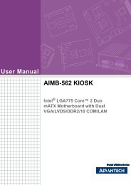
<strong>T10C</strong> User <strong>Guide</strong>Chapter 2System Setup2.1. Exploring Your <strong>T10C</strong>Before starting to set up the <strong>T10C</strong>, get familiar with the locations andpurpose of controls, connectors and I/O ports, which are illustrated in thefigures below. When placed upright, the front panel of the <strong>T10C</strong> appears asshown in below.2.1.1. The <strong>T10C</strong> IOThe <strong>T10C</strong> I/O is as described below.20
<strong>T10C</strong> User <strong>Guide</strong>F1 ButtonF2 ButtonF3 ButtonF4 ButtonF5 ButtonFn ButtonF1=explorerF2=Windows Media PlayerF3=OnScreen keyboardF4=Task ManagerF5=CalculatorFn = Hotkey UtilityImplement Secure AttentionSequence (SAS)Fn+F3 Button (SAS)Similar function as pressingCtrl-Alt-Delete on a standardkeyboardF1 KEY -LEFT ARROWFunction Key mapping during boot(for Windows system recovery) is asfollows:F2 KEY -UP ARROWF3 KEY -ENTERF4 KEY -RIGHT ARROWF5 KEY -DOWN ARROW• Camera/2 Mega-pixelThe built-in camera can be used as a communication device forallowing you to capture images, record videos, and have videochats. It is 2M pixels and transmitting instant image throughnetwork for conference.21
<strong>T10C</strong> User <strong>Guide</strong>• Digital MicrophoneThe built-in microphone receives sounds and voices when usedwith the built-in camera.• LED Power/Storage/Wi-FiKeeps you informed of your system’s current power status, Storageaccess status, and Wi-Fi ON/OFF status.1. Power Indicator LED 2. Storage Access3. WiFi ON/OFF22Power Indicator LEDTo let you know that system is turned on and indicate thebattery charging status.Lights green when the system is powered on andbattery is discharging or when the system is poweredon and battery is fully chargedLights blinking red when the system is in S3 Suspendand battery is charging or when the system is in S3Suspend and battery is fully chargedLights red when the system is powered on and batteryis charging.Lights blinking red indicates that the battery is incharging and system is power off / S3 Suspend
<strong>T10C</strong> User <strong>Guide</strong>Lights off when power off or the battery is fullycharged.Storage AccessWhen LED in blue light indicates that the system isaccessing the Storage Drive.WiFi ON/OFFWhen LED turns on, blue light indicates that the WiFi isactivated. When LED lights off, it indicates that the WiFifunction is disabled.• User Interface ButtonThis button is used to define the User Interface function. When youpress this button, the system will appear the UI screen as illustratedbelow for executing the applications easily and quickly.• Programmable Function ButtonsIf your system does not define this button’s function, this button canbe programmable to execute specific application. When youprogram your application, please write this directory as listed belowinto your configuration file, then the system will aware and executethis application.[Setup]F1_EXE="c:\windows\explorer.exe"F1_PARA=""F1_PATH=""F2_EXE="C:\Program Files\Windows Media Player\wmplayer.exe"F2_PARA="/prefetch: 1"F2_PATH=""23F3_EXE="C:\WINDOWS\system32\osk.exe"F3_PARA=""
<strong>T10C</strong> User <strong>Guide</strong>F3_PATH=""F4_EXE="C:\WINDOWS\system32\taskmgr.exe"F4_PARA=""F4_PATH=""The configuration file is "c:\FKeySet.txt"• Camera/5Mega-pixelThe built-in camera can be used as a communication device forallowing you to capture images, record videos, and have videochats. It is 5.0 M pixels and transmitting instant image throughnetwork for conference.• Power ButtonSwitch the computer power on and off, or resumes whenever it is inSuspend mode (by OS define).• USB PortsThe two USB (type-A) ports allows you to connect USB2.0-compliant devices (for example, mouse, keyboard and so on) toyour <strong>Tablet</strong> <strong>PC</strong>.• 3.5mm Headphone JackAllows you to connect an external 3.5mm 4-conductor TRRS(stereo-plus-mic) headphone for personal listening and soundrecording.• Ethernet JackThe 10/100Mbps Ethernet port allows you to connect to othercomputers/networks through a local area network (LAN).• Accessory Door24
<strong>T10C</strong> User <strong>Guide</strong>By removing the two long screws on top side of the system, allowsyou to install optional snap-on module.• External Battery ConnectorTo install the external battery pack, install external battery holderfirst and remove the cover of external battery connector beforesnap the battery pack into the external battery connector.• SpeakerIntegrated stereo speaker for sound and audio output for yourmultimedia presentations or listening pleasure.• Protective RubberTo prevent system harm from vibration or shock, the system isdesigned with installing protective rubber on four corners.• DC-JackLets you connect the AC power adapter in supplying continuouspower to your <strong>Tablet</strong> <strong>PC</strong> and recharging the battery.The AC adapter provides external power source to your systemand charges the internal battery pack at the same time. The ACadapter also has an auto-switching design that can connect to any100VAC ~ 240VAC power outlets.To connect the power adapter:1. Plug the AC adapter connector to the DC-Jack socket on theright side of the system.2. Plug the power cord to the AC adapter.Plug the other end of the power cord to a live walloutlet, at the same time, the Power LED at front panellights up.25
<strong>T10C</strong> User <strong>Guide</strong>-- For the power supply of this equipment, an approved powercord hasto be used.-- Make sure the socket and any extension cord(s) you use cansupportthe total current load of all the connected devices.-- Remove all power from the device prior to installing or removinganyaccessories, hardware, or cables-- Before cleaning the system, make sure it is disconnectedfromany external power supplies (i.e. AC adapter).• Docking ConnectorLets you connect the system to docking station to dock the tablet<strong>PC</strong> when you are at home or office desk.2.2.Preparing for InstallationYour <strong>T10C</strong> is designed and pre-configured for easy setup and use. Thissection describes the installation steps you should follow to get thesystem running as quickly as possible.2.2.1.Switch ON the main batterya. Main battery switch is located on rear side of yellow labelbattery doorb. Adjust DIP switch to “ON”26
<strong>T10C</strong> User <strong>Guide</strong>c. Place back the battery door2.2.2.Plugging to the DC supplyThe AC adapter provides external power source to your system andcharges the internal battery pack at the same time. The AC adapteralso has an auto-switching design that can connect to any 100VAC ~240VAC power outlets.To connect the power adapter:3. Plug the AC adapter connector to the DC-Jack socket on the leftside of the system.4. Plug the power cord to the AC adapter.27
<strong>T10C</strong> User <strong>Guide</strong>5. Plug the other end of the power cord to a live wall outlet, at thesame time, the Power LED at front panel lights up.-- For the power supply of this equipment, an approved power cord hasto be used.-- Make sure the socket and any extension cord(s) you use can supportthe total current load of all the connected devices.-- Remove all power from the device prior to installing or removing anyaccessories, hardware, or cables-- Before cleaning the system, make sure it is disconnected fromany external power supplies (i.e. AC adapter).2.2.3.Starting Your SystemThe Power/Resume button is found on the right side of the <strong>Tablet</strong> <strong>PC</strong>.Press the Power/Resume button to start your system and check that ifthe Power LED turns on.After a few seconds, the system’s display will turn on and your systemwill begin to execute the Power On Self Test or POST to check if allsystem components are running properly. Any error found during thetest will be displayed on the screen.After the test, the screen will also display a message "press toenter SETUP". You don’t need to run this program at the moment asyour dealer already made the necessary settings for your computer28
<strong>T10C</strong> User <strong>Guide</strong>optimal operation.After the test has completed, your computer will start to search andboot up the operating system from your hard drive.2.2.4.Connecting the keyboard and mouseBefore setting up the system, please make sure the following items areavailable.• Keyboard• Mouse (for system software installation)A keyboard is an input device; a mouse is a pointing device. Pleaseconnect these two devices as graphics shown below to interact withyour system.29
<strong>T10C</strong> User <strong>Guide</strong>Chapter 3Using the <strong>T10C</strong>3.1.IntroductionThis chapter describes the basic features and procedures for using thepanel <strong>PC</strong>. It includes the I/O ports connecting and the touch screenoperation.3.2.Using the USB PortsUSB (Universal Serial Bus) is a hardware interface that enables you toconnect multiple devices (such as printers, mice, keyboards, storagedevices, joysticks, digital cameras, and video conference cameras, etc.)to your tablet pc and up to 127 devices can be attached. Besides,USB’s hot swap capability allows everything to be plugged in andunplugged without turning the system off.USB 2.0 is fully backward compatible, you will be able to use an USB1.1 device in an USB 2.0 compliant system.1. Connect the external device to the system.2. The USB ports support hot plug-in connections. Install the devicedriver before using the device.30
<strong>T10C</strong> User <strong>Guide</strong>3.3.Using the External Audio SystemAt the right side of your <strong>Tablet</strong> <strong>PC</strong>, you will find the built-in audio portsfor connecting Microphone jacks, earphone or powered speaker.To connect to an audio jack:1. Locate the audio ports (Microphone and Headphone) that youwant to use to the target device.2. Plug the jack into the port on the right side of the system.3.4.Installing the Battery (optional)<strong>T10C</strong> provides optional external battery to extend the power of yoursystem.For installing the battery pack, please follow the steps below:1. Turn off the system.2. Align the hook wall at the rear side, then place and screw itsecurely.313. Remove the cover of the external battery connector (as marked below) and place it on the lower position (as marked below).
<strong>T10C</strong> User <strong>Guide</strong>4. Snap the battery pack into the external battery connector andlatch into the hook wall securely.For removing the external battery, repeat the above steps in reverseorder to remove the battery.3.5.Using a SIM CardYour <strong>T10C</strong> can be equipped with a 3.5G module (optional) that canwork with SIM card. (SIM card is always working with 3.5G module.)3.5.1.Inserting a SIM CardTo insert a SIM card into the SIM Card slot:1. Turn off your System.The <strong>T10C</strong> must be powered off while the SIM Card is being connected.Otherwise, it is harmful to both devices and it shortens the life of thesedevices.2. Unscrew the optional accessory cover on top of the <strong>Tablet</strong> <strong>PC</strong>.32
<strong>T10C</strong> User <strong>Guide</strong>3. Make sure the clipped corner facing inward with the metallic label ofthe card facing down. Push the SIM Card firmly but slowly into theSIM Card slot.To insert a SIM card into the slot, please pay attention only one correctside can be accepted for the card slot. If you cannot insert the card intothe slot or you had inserted the card but it is not recognized by the <strong>Tablet</strong><strong>PC</strong>, please remove the card and insert it again. To prevent the damagemade both on card and the slot, never forced an entry into the slot withincorrect side.4. When the full length of the card is almost inside the slot, the SIMCard will be automatically detected.5. Place the optional accessory cover back to the place and screw itfirmly on top of the system.3.5.2.Removing a SIM CardTo remove a SIM Card from the SIM Card slot:1. Turn off your system.2. Slightly push the SIM card to pop it out and pull it out directly. Whenthe SIM card has moved out a space out of the slot, hold the edgesof the card and slowly slide it out.3.6. Using a Barcode Scanner Module33
<strong>T10C</strong> User <strong>Guide</strong>or MSR (optional)The <strong>T10C</strong> System provides barcode scanner and MSR functions for youroptional selection, before installing either of these two modules on the topside of the system, please remove the screws previously (illustrated in thefollowing graphics as indicated step 1).To install the Barcode Scanner /MSR Module:1. Make sure the system is turned off. Unscrew four screws from theaccessory door on top of the system.2. Mount and secure the Barcode/MSR daughter board intothe mainboard with screws.34
<strong>T10C</strong> User <strong>Guide</strong>3. Insert FFC cable of barcode scanner into connector slot orattached the MSR cable to the connectors on the daughterboard.4. Screw to secure the Barcode Scanner/MSR onto the tablet.35
<strong>T10C</strong> User <strong>Guide</strong>Chapter 4The BIOS SetupProgramThis system comes with a chip from Phoenix BIOS that contains the ROMSetup information for your system. (This chip serves as an interfacebetween the processor and the rest of the system components.) Thissection explains the information contained in the Setup program and tellsyou how to modify the settings according to your system configuration.The Setup utility program allows updates to the main board configurationsettings. The BIOS setup values will be saved in the CMOS. It is executedwhen you change the system configuration, you change the system backupbattery, or the system detects a configuration error and asks you to run theSetup program. You must have connected a USB type of keyboard, andUse the arrow keys to select, and press Enter to run the selected program.Function KeyPlease check the following table for the function description of eachdirection key. / / 36FunctionKey (s)Function DescriptionMoves cursor left or right to select menu onmenu bar.Moves cursor up or down to select items
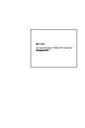
<strong>T10C</strong> User <strong>Guide</strong>+ / -FunctionKey (s)Function DescriptionTo change option for the selected itemsTo bring up the selected screenTo display the General Help screenTo load bios setup defaults value.To save changes and exit the BIOS SETUPUTILITYTo jump to the Exit Screen or exit the currentscreen4.1.Main Screen Setup UtilityWhen you enter the BIOS SETUP UTILITY, the Main screen will appearand display the system overview.37
<strong>T10C</strong> User <strong>Guide</strong>The Standard CMOS Setup screen is displayed above. Each featuremay have one or more option settings. Use the arrow keys to highlightthe feature you want to change and then use “”or “” to select thevalue you want for that feature.NOTE: The system BIOS automatically detects EC version, boardversion, Processor, memory size, thus no changes are necessary.• System DateTo set the date, highlight the Date field and then press +/- keys toset the current date. Follow the month, day and year format.• System TimeTo set the time, highlight the Time field and then press +/- keys toset the current time. Follow the hour, minute, and second format.• BIOS VersionThe system will automatically displays the information of BIOSversion.• Build TimeThe system will automatically displays the build time of BIOS.• EC VersionThe system will automatically displays the information of EC(Embedded Controller) firmware version.• VBIOS VersionThe system will automatically displays the information of VBIOSversion of internal graphics.• Board VersionThe system will automatically displays the information of <strong>PC</strong>Bversion of mainboard.• Processor TypeThe system will automatically displays the information of ProcessorType and speed.38
<strong>T10C</strong> User <strong>Guide</strong>• System Memory SpeedThe system will automatically displays the information of SystemMemory Speed.• L2 Cache RAMThe system will automatically displays the information of L2 CacheRAM.• Total MemoryThe system will automatically displays the information of TotalMemory.4.2.Advanced BIOS FeaturesFor Advanced Settings, the BIOS will automatically display the Platforminformation and let you define the configuration when system booting.In this section, you may set the configurations for the following items:Quick boot, UEFI boot, Legacy boot, and Boot Priority.39
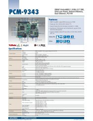
<strong>T10C</strong> User <strong>Guide</strong>• Select LanguageLets you select the language displayed in SETUP UTILITY. (Thecurrent BIOS support the languages of English, Japanese andFrench.)• UEFI BootLets you activate or close the UEFI boot function by selectingEnabled or Disabled option.• Legacy BootLets you activate or close the Legacy boot function by selectingEnabled or Disabled option.• Boot PriorityLets you set the boot priority from UEFI boot or HDD boot.4.3.Security Chip Configuration40
<strong>T10C</strong> User <strong>Guide</strong>• Supervisor Password is:This option displays the status of Supervisor Password. If thepassword is entered, it will display “Set” information, or it willdisplay “Cleared” information when there is no password setting.• User Password isThis option displays the status of User Password. If the password isentered, it will display “Set” information, or it will display “Cleared”information when there is no password setting.• Set Supervisor PasswordThis field let you set or clear the Supervisor account’s password.• Set User PasswordThis field let you set or clear the User account’s password.• TPM SupportLets you activate or close the TPM function by selecting Enabled orDisabled option. (For the non-TPM SKU, this item will display “nodetected”.)41
<strong>T10C</strong> User <strong>Guide</strong>4.4.Boot Management SetupThis page allows you to set the search drive sequence where thesystem will try to boot up first.To select the boot device, you can use the up or down arrow key, thenpress to move up the device in the list or press to move downthe device in the list. To exit from this menu, press .42
<strong>T10C</strong> User <strong>Guide</strong>4.5.Exit Control• Exit Saving ChangesWhen you select this option, it will pop-out the following message,“Save configuration changes and exit setup?” Select [OK] to savethe changes and exit the BIOS SETUP UTILITY.• Exit Discarding ChangesWhen you select this option, it will pop-out the following message,“Discard changes and exit setup?”. Select [OK] to exit the BIOSSETUP UTILITY without saving any changes.• Load Setup DefaultsWhen you select this option, it will pop-out the following message,“Load optimal defaults?” Select [OK] to load the default values forall the setup configurations.• Save ChangesWhen you select this option, it will pop-out the following message,“Save changes?” Select [OK] to save all changes.43
<strong>T10C</strong> User <strong>Guide</strong>Chapter 5User Interface for<strong>T10C</strong>5.1.IntroductionThis user interface provides specific mobile utility to let you easilysetup some helpful functions and aware the system status directly.This utility also let you adjust some function to fit the requirements,such as brightness and volume adjustment, webcam launch, screenorientation and monitor switching.Furthermore, it also provides system information for your reference,such as battery status, RF setting with its signal strength, firmware(BIOS & EC) version information. Besides these features, you canpress the soft button to hibernate this device.5.2.About the User Interface5.2.1.Enable or disable the User InterfaceTo display the User Interface, please press the Fn button or point theHot key Utility on the screen.To close the User Interface function, please press thebutton on44
<strong>T10C</strong> User <strong>Guide</strong>the top right corner on this User Interface for disabling this utility fromthe screen.If there is no action took for this utility in 5 seconds, the UI screen willclose automatically.5.2.3.System Status InformationThis utility shows you the battery capacity status, RF status with itssignal strength and system information, and provides the control panelfor the function setting.45
<strong>T10C</strong> User <strong>Guide</strong>For battery capacity status:The <strong>T10C</strong> is equipped with one internal battery and one optionalexternal battery.The battery capacity status shown below advises you, that only oneinternal battery is embedded with the system which is fully charged,and there is no 2 nd optional battery installed in the system.If the system installs both the 1st internal battery and 2nd optionalbattery, the illustration shown below indicates its current chargingstatus and capacity.If 1st battery capacity drops to 15%, the system will display thefollowing warning message for 5 seconds.46
<strong>T10C</strong> User <strong>Guide</strong>For RF status:The following RF status shows you that the system is equipped withWi-Fi, and Bluetooth functions. If you want to close either of thesefunctions, please refer section for how to disable it.The following signal strength shows you that the Wi-Fi function isconnecting currently, the stronger the signal strength, the more scalewill show on the bar. If there is no module in the system, there will beno status scale in the following status bar.47
<strong>T10C</strong> User <strong>Guide</strong>For System Information :The system information shown on the left shows you the hotkey utilityversion, BIOS and EC version and you can use them for customerservice when asked.5.3.Using the ApplicationYour <strong>T10C</strong> has numbers of applications on the control panel for executingspecific command. It provides you to adjust brightness, volume, launchwebcam, make screen orientation and switch monitor.5.3.1.Brightness ControlFor brightness adjustment, press the Brightnesscommand.48
<strong>T10C</strong> User <strong>Guide</strong>When you press it, the brightness control panel is appeared as follows:• You can click or to reduce or increase thebrightness.• Also, you can slide the scale bar to set thebrightness.• Since the system supports the light sensor, if you tick thebrightness Auto adjustment, the screenbrightness will automatically adjust according to the operatingenvironment.5.3.2.Volume ControlFor Volume adjustment, press the Volumecommand.49
<strong>T10C</strong> User <strong>Guide</strong>When you press it, the Volume control panel is appeared as follows:• You can click or to reduce or increase the audiovolume incrementally.• Also, you can slide the scale bar to set theaudio volume.• You can tick the Mute to mute the audio.5.3.3.Webcam LaunchFor Webcam Launch, press the WebcamWebcam utility.icon to launch the50
<strong>T10C</strong> User <strong>Guide</strong>5.3.4.Monitor SwitchFor Monitor switch, press the Monitor Switch to pop-up theselection bar for choosing the display mode within following fouroptions.• You can click Duplicate to display the same contentsboth on the <strong>T10C</strong> screen and external display device. Theresolution on these two display modes are same, it is notavailable to adjust the resolution on the external display mode.• You can click Extend to display the differentcontents on the <strong>T10C</strong> screen and external display device. Youonly can adjust the resolution on the external display device.• You can click Projector only to display on external51
<strong>T10C</strong> User <strong>Guide</strong>projector only.•5.3.5.RF Device ON/OFF ControlPress this soft button (via hotkey utility menu) to enable or disableWi-Fi, Bluetooth, WWAN, or GPS devices. When you press the RFON/OFF soft button, the screen pops-up the option list for yourselection.You can see all functions in this option list have been ticked. To closeany device function, please touch the option to close the execution asshown in the following graphics.52
<strong>T10C</strong> User <strong>Guide</strong>Disable Wi-Fi functionDisable Bluetooth functionDisable WWAN functionDisable GPS functionTo activate the function, please again tick the option as shown in thefollowing graphics to make the device enable.Activate Wi-Fi functionActivate Bluetooth function53
<strong>T10C</strong> User <strong>Guide</strong>Activate WWAN functionActivate GPS function54
<strong>T10C</strong> User <strong>Guide</strong>Chapter 6MaintenanceYour <strong>T10C</strong> needs occasional cleaning to prolong their life. Please readthis section carefully to ensure proper care of <strong>T10C</strong>. When it is necessaryto clean it, use a soft, lint-free cloth, slightly dampened with a milddetergent solution or use the contents of any commercially availablecomputer cleaning kit.Never use petroleum-based solvents, or harsh detergents to clean thesystem. Also never spray any liquids directly on the computer case orscreen. If the display screen has become smeared or dusty, clean thescreen by first applying a mild glass cleaner to a soft, clean, lint-free cloth,and gently wipe the glass. Never apply liquids directly on the screensurface. Moreover, do not use paper towels to clean the display screen.Paper can scratch the display screen matte.6.1.Maintaining the Battery• Do not expose heat or attempt to disassemble the battery, anddo not place the battery in water or in a fire.• Do not subject the battery to strong impact, such as a blow froma hammer, or stepping on or dropping it.• Do not puncture or disassemble the battery.• Do not attempt to open or service the battery.• Replace only with batteries designed specifically for this product.• Keep the battery out of reach of children.55
<strong>T10C</strong> User <strong>Guide</strong>• Dispose of used batteries according to local regulations.6.2.Maintaining the LCD Display• Do not scratch the surface of the screen with any hard objects.• Do not spray liquid directly on the screen or allow excess liquidto drip down inside the device.• Do not place anything, such as food and drink, on the screen atany time to prevent damage to the screen.• Clean the LCD display only with a soft cloth dampened withdenatured alcohol or a proprietary LCD screen cleaner.6.3.Cleaning the <strong>T10C</strong>• Turn off the <strong>T10C</strong> and unplug the power cord.• Wipe the screen and exterior with a soft, damp cloth moistenedonly with water. Do not use liquid or aerosol cleaners on thescreen, as these will discolor the finish and damage the screen.56