guideline for use of fizeau interferometer in optical testing - NASA
guideline for use of fizeau interferometer in optical testing - NASA
guideline for use of fizeau interferometer in optical testing - NASA

Create successful ePaper yourself
Turn your PDF publications into a flip-book with our unique Google optimized e-Paper software.
GUIDELINE NO. GT-TE-2404<br />
PAGE 2 OF 11<br />
GUIDELINE FOR USE OF FIZEAU<br />
INTERFEROMETER IN OPTICAL TESTING<br />
<strong><strong>in</strong>terferometer</strong>. The surface adjacent to the collimat<strong>in</strong>g lens is <strong>of</strong> good <strong>optical</strong> quality. However, the<br />
next surface is <strong>of</strong> exceptional <strong>optical</strong> quality, 8/20 peak to valley (PV) or better. This is the reference<br />
surface and part <strong>of</strong> the collimated beam is reflected by this surface. Part <strong>of</strong> the collimated beam<br />
cont<strong>in</strong>ues on to <strong>in</strong>terrogate the optic be<strong>in</strong>g tested. The return beam conta<strong>in</strong>s <strong>in</strong><strong>for</strong>mation on<br />
aberration <strong>in</strong>troduced by the test optic. The two wavefronts recomb<strong>in</strong>e <strong>in</strong>side the <strong><strong>in</strong>terferometer</strong>.<br />
The beam-splitter diverts the comb<strong>in</strong>ed beams toward a record<strong>in</strong>g medium, either film or a TV (CCD<br />
or vidicon). An <strong>in</strong>termediate lens together with the collimat<strong>in</strong>g lens <strong>for</strong>ms an image <strong>of</strong> the test surface<br />
onto the record<strong>in</strong>g plane. An observer will see a sharp image <strong>of</strong> the test surface with an <strong>in</strong>terference<br />
(or fr<strong>in</strong>ge) pattern runn<strong>in</strong>g through it.<br />
Application <strong>of</strong> Fizeau Interferometer<br />
1. Test<strong>in</strong>g a Flat<br />
Suppose the test object is a plane glass surface whose quality (flatness) we wish to <strong>in</strong>spect. We must<br />
first align the test surface to the <strong><strong>in</strong>terferometer</strong>. Most commercial Fizeau <strong><strong>in</strong>terferometer</strong>s have an<br />
"align mode." This requires the <strong>use</strong>r to center a bright dot (the reflected return) on a crosshair on<br />
some view<strong>in</strong>g screen.<br />
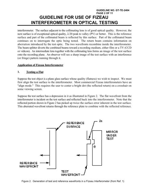
Suppose the test surface has a depression <strong>in</strong> it as illustrated <strong>in</strong> Figure 2. The flat wavefront from the<br />
<strong><strong>in</strong>terferometer</strong> is <strong>in</strong>cident on the test surface and reflected back <strong>in</strong>to the <strong><strong>in</strong>terferometer</strong>. Note that the<br />
reflected portion shown <strong>in</strong> Figure 2 has picked up twice the surface error <strong>in</strong>herent <strong>in</strong> the test surface.<br />
This aberrated wavefront returns through the reference plate to comb<strong>in</strong>e with the reflected reference.<br />
Figure 2. Generation <strong>of</strong> test and reference wavefronts <strong>in</strong> a Fizeau Interferometer (from Ref. 1)