guideline for use of fizeau interferometer in optical testing - NASA
guideline for use of fizeau interferometer in optical testing - NASA
guideline for use of fizeau interferometer in optical testing - NASA

Create successful ePaper yourself
Turn your PDF publications into a flip-book with our unique Google optimized e-Paper software.
GUIDELINE NO. GT-TE-2404<br />
PAGE 8 OF 11<br />
GUIDELINE FOR USE OF FIZEAU<br />
INTERFEROMETER IN OPTICAL TESTING<br />
1,3,4<br />
ray. This is retrace error (also called ray-mapp<strong>in</strong>g error) . As a consequence, it is no longer true<br />
that we can simply divide the results by two to obta<strong>in</strong> the s<strong>in</strong>gle pass wavefront aberration from<br />
double pass fr<strong>in</strong>ge data.<br />
There are some visual clues to <strong>in</strong>dicate if retrace error is significant. First, with the room darkened,<br />
check to see that the beam diameter <strong>of</strong> the light return<strong>in</strong>g through the test optic on the second-pass<br />
is the same as that <strong>for</strong> the first pass after sett<strong>in</strong>g the null-fr<strong>in</strong>ge. Second, exam<strong>in</strong>e the irradiance<br />
distribution <strong>of</strong> this second-pass beam at the test optic. If the second-pass beam overfills or underfills<br />
the test optic aperture, and/or the <strong>in</strong>tensity distribution is nonuni<strong>for</strong>m, then retrace error is significant<br />
<strong>in</strong> the test setup.<br />
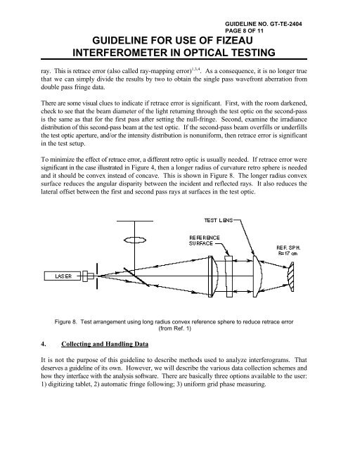
To m<strong>in</strong>imize the effect <strong>of</strong> retrace error, a different retro optic is usually needed. If retrace error were<br />
significant <strong>in</strong> the case illustrated <strong>in</strong> Figure 4, then a longer radius <strong>of</strong> curvature retro sphere is needed<br />
and it should be convex <strong>in</strong>stead <strong>of</strong> concave. This is shown <strong>in</strong> Figure 8. The longer radius convex<br />
surface reduces the angular disparity between the <strong>in</strong>cident and reflected rays. It also reduces the<br />
lateral <strong>of</strong>fset between the first and second pass rays at surfaces <strong>in</strong> the test optic.<br />
Figure 8. Test arrangement us<strong>in</strong>g long radius convex reference sphere to reduce retrace error<br />
(from Ref. 1)<br />
4. Collect<strong>in</strong>g and Handl<strong>in</strong>g Data<br />
It is not the purpose <strong>of</strong> this <strong>guidel<strong>in</strong>e</strong> to describe methods <strong>use</strong>d to analyze <strong>in</strong>terferograms. That<br />
deserves a <strong>guidel<strong>in</strong>e</strong> <strong>of</strong> its own. However, we will describe the various data collection schemes and<br />
how they <strong>in</strong>terface with the analysis s<strong>of</strong>tware. There are basically three options available to the <strong>use</strong>r:<br />
1) digitiz<strong>in</strong>g tablet, 2) automatic fr<strong>in</strong>ge follow<strong>in</strong>g; 3) uni<strong>for</strong>m grid phase measur<strong>in</strong>g.