guideline for use of fizeau interferometer in optical testing - NASA
guideline for use of fizeau interferometer in optical testing - NASA
guideline for use of fizeau interferometer in optical testing - NASA

You also want an ePaper? Increase the reach of your titles
YUMPU automatically turns print PDFs into web optimized ePapers that Google loves.
Guidel<strong>in</strong>e:<br />
PREFERRED<br />
RELIABILITY<br />
PRACTICES<br />
GUIDELINE NO. GT-TE-2404<br />
PAGE 1 OF 11<br />
GUIDELINE FOR USE OF<br />
FIZEAU INTERFEROMETER<br />
IN OPTICAL TESTING<br />
The Fizeau <strong><strong>in</strong>terferometer</strong> is the most commonly <strong>use</strong>d <strong><strong>in</strong>terferometer</strong> <strong>for</strong> test<strong>in</strong>g <strong>optical</strong> components<br />
and systems <strong>use</strong>d aboard spaceborne or space-related <strong>in</strong>strumentation. This <strong>guidel<strong>in</strong>e</strong> provides<br />
<strong>in</strong><strong>for</strong>mation on the proper <strong>use</strong> <strong>of</strong> this <strong>in</strong>strument.<br />
Benefit:<br />
The Fizeau <strong><strong>in</strong>terferometer</strong> is <strong>use</strong>d to measure the quality <strong>of</strong> <strong>optical</strong> components and systems. It<br />
provides a guide <strong>for</strong> the manufactur<strong>in</strong>g <strong>of</strong> components, an aid <strong>for</strong> alignment, and a validation <strong>of</strong><br />
system per<strong>for</strong>mance.<br />
Center to Contact <strong>for</strong> More In<strong>for</strong>mation:<br />
Goddard Space Flight Center (GSFC)<br />
Implementation Method:<br />
Description <strong>of</strong> Fizeau Interferometer<br />
1<br />
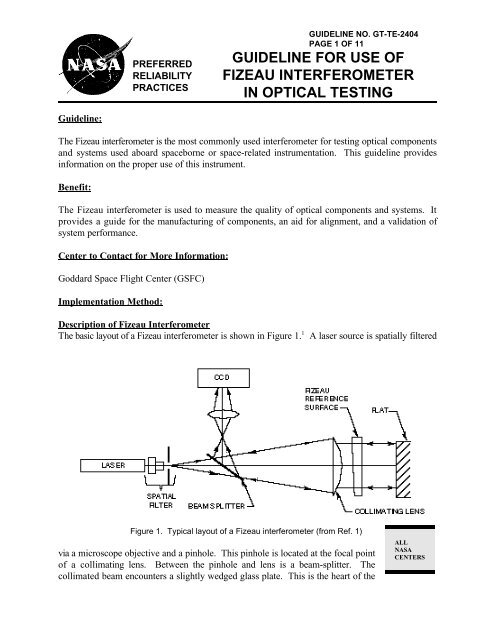
The basic layout <strong>of</strong> a Fizeau <strong><strong>in</strong>terferometer</strong> is shown <strong>in</strong> Figure 1. A laser source is spatially filtered<br />
Figure 1. Typical layout <strong>of</strong> a Fizeau <strong><strong>in</strong>terferometer</strong> (from Ref. 1)<br />
via a microscope objective and a p<strong>in</strong>hole. This p<strong>in</strong>hole is located at the focal po<strong>in</strong>t<br />
<strong>of</strong> a collimat<strong>in</strong>g lens. Between the p<strong>in</strong>hole and lens is a beam-splitter. The<br />
collimated beam encounters a slightly wedged glass plate. This is the heart <strong>of</strong> the<br />
ALL<br />
<strong>NASA</strong><br />
CENTERS
GUIDELINE NO. GT-TE-2404<br />
PAGE 2 OF 11<br />
GUIDELINE FOR USE OF FIZEAU<br />
INTERFEROMETER IN OPTICAL TESTING<br />
<strong><strong>in</strong>terferometer</strong>. The surface adjacent to the collimat<strong>in</strong>g lens is <strong>of</strong> good <strong>optical</strong> quality. However, the<br />
next surface is <strong>of</strong> exceptional <strong>optical</strong> quality, 8/20 peak to valley (PV) or better. This is the reference<br />
surface and part <strong>of</strong> the collimated beam is reflected by this surface. Part <strong>of</strong> the collimated beam<br />
cont<strong>in</strong>ues on to <strong>in</strong>terrogate the optic be<strong>in</strong>g tested. The return beam conta<strong>in</strong>s <strong>in</strong><strong>for</strong>mation on<br />
aberration <strong>in</strong>troduced by the test optic. The two wavefronts recomb<strong>in</strong>e <strong>in</strong>side the <strong><strong>in</strong>terferometer</strong>.<br />
The beam-splitter diverts the comb<strong>in</strong>ed beams toward a record<strong>in</strong>g medium, either film or a TV (CCD<br />
or vidicon). An <strong>in</strong>termediate lens together with the collimat<strong>in</strong>g lens <strong>for</strong>ms an image <strong>of</strong> the test surface<br />
onto the record<strong>in</strong>g plane. An observer will see a sharp image <strong>of</strong> the test surface with an <strong>in</strong>terference<br />
(or fr<strong>in</strong>ge) pattern runn<strong>in</strong>g through it.<br />
Application <strong>of</strong> Fizeau Interferometer<br />
1. Test<strong>in</strong>g a Flat<br />
Suppose the test object is a plane glass surface whose quality (flatness) we wish to <strong>in</strong>spect. We must<br />
first align the test surface to the <strong><strong>in</strong>terferometer</strong>. Most commercial Fizeau <strong><strong>in</strong>terferometer</strong>s have an<br />
"align mode." This requires the <strong>use</strong>r to center a bright dot (the reflected return) on a crosshair on<br />
some view<strong>in</strong>g screen.<br />
Suppose the test surface has a depression <strong>in</strong> it as illustrated <strong>in</strong> Figure 2. The flat wavefront from the<br />
<strong><strong>in</strong>terferometer</strong> is <strong>in</strong>cident on the test surface and reflected back <strong>in</strong>to the <strong><strong>in</strong>terferometer</strong>. Note that the<br />
reflected portion shown <strong>in</strong> Figure 2 has picked up twice the surface error <strong>in</strong>herent <strong>in</strong> the test surface.<br />
This aberrated wavefront returns through the reference plate to comb<strong>in</strong>e with the reflected reference.<br />
Figure 2. Generation <strong>of</strong> test and reference wavefronts <strong>in</strong> a Fizeau Interferometer (from Ref. 1)
GUIDELINE NO. GT-TE-2404<br />
PAGE 3 OF 11<br />
GUIDELINE FOR USE OF FIZEAU<br />
INTERFEROMETER IN OPTICAL TESTING<br />
Wherever two coherent wavefronts overlap they <strong>in</strong>terfere with each other. The equation describ<strong>in</strong>g<br />
2 <strong>in</strong>terference is as follows:<br />
I(x,y)' I 1 % I 2 % 2 I 1 I 2 cos N(x,y)<br />
To obta<strong>in</strong> good high contrast fr<strong>in</strong>ges requires that the reflection <strong>of</strong>f the reference and <strong>of</strong>f the test<br />
piece must be equivalent <strong>in</strong> <strong>in</strong>tensity. Maximum fr<strong>in</strong>ge contrast occurs when I 1 = I 2.<br />
For example,<br />
a bare glass test surface reflects 4%. To maximize fr<strong>in</strong>ge contrast the reference surface must also<br />
reflect 4%.<br />
If a 4% reference surface is <strong>use</strong>d to test a mirror (with 90% plus reflectivity), then a very th<strong>in</strong><br />
beam-splitter (e.g., a pellicle) can be <strong>use</strong>d to reduce the <strong>in</strong>tensity from the test optic. Alternatively,<br />
a reference surface hav<strong>in</strong>g a much higher reflectivity can be <strong>use</strong>d to improve fr<strong>in</strong>ge contrast. In the<br />
latter case, one will notice that the dark fr<strong>in</strong>ges become much th<strong>in</strong>ner, like sharp pencil l<strong>in</strong>es.<br />
A sample <strong>in</strong>terferogram <strong>of</strong> a supposed "flat" mirror is shown <strong>in</strong> Figure 3. If the mirror were flat,<br />
equally spaced straight l<strong>in</strong>e fr<strong>in</strong>ges should be observed (depend<strong>in</strong>g on the relative tilt between the<br />
reference surface and the test surface). Obviously, the mirror is not very flat at all. Each fr<strong>in</strong>ge is a<br />
height contour as <strong>in</strong> a topographical map.<br />
(The metric or unit <strong>of</strong> measure <strong>in</strong> most<br />
Fizeau <strong><strong>in</strong>terferometer</strong>s is the wavelength <strong>of</strong><br />
the source. For example, the helium near<br />
laser wavelength is 0.6328 microns.) The<br />
height difference between each contour or<br />
fr<strong>in</strong>ge is 1 wave. If knowledge <strong>of</strong> the<br />
surface error or its departure from flatness<br />
is desired, we must <strong>in</strong>terpret these fr<strong>in</strong>ges as<br />
represent<strong>in</strong>g half-wave contours!<br />
In addition we must know whether the<br />
pattern seen <strong>in</strong> Figure 3 is a hill or a valley<br />
on the mirror surface. This can be<br />
determ<strong>in</strong>ed by plac<strong>in</strong>g your f<strong>in</strong>ger on the<br />
front <strong>of</strong> the reference surface metal support<br />
r<strong>in</strong>g (Figure 1) and press<strong>in</strong>g lightly toward<br />
the <strong><strong>in</strong>terferometer</strong> hous<strong>in</strong>g. If the fr<strong>in</strong>ge<br />
patterns collapse or contract, the pattern<br />
represents a hill or bump. If they expand,<br />
the pattern represents a valley.<br />
(1)<br />
Figure 3. Interferogram <strong>of</strong> a "flat" mirror (from Ref. 1)
GUIDELINE NO. GT-TE-2404<br />
PAGE 4 OF 11<br />
GUIDELINE FOR USE OF FIZEAU<br />
INTERFEROMETER IN OPTICAL TESTING<br />
2. Test<strong>in</strong>g a Lens<br />
The setup <strong>for</strong> test<strong>in</strong>g a lens is illustrated <strong>in</strong> Figure 4. The lens is carefully aligned to the Fizeau beam.<br />
The beam is foc<strong>use</strong>d by the lens to an image po<strong>in</strong>t. To return the beam back to the <strong><strong>in</strong>terferometer</strong><br />
another auxiliary reference surface is needed. In this example a small concave spherical mirror is<br />
<strong>use</strong>d. This sphere should be mounted so that X,Y, and Z translation degrees <strong>of</strong> freedom are available.<br />
The center <strong>of</strong> curvature <strong>of</strong> the sphere is then made co<strong>in</strong>cident with the focal po<strong>in</strong>t <strong>of</strong> the lens. (Be<br />
careful—make sure that the focussed beam is not on the surface <strong>of</strong> the small retro sphere). The beam<br />
is reflected by the reference sphere and returned through the system.<br />
The <strong>in</strong>terferogram that is <strong>in</strong>itially seen is likely to be an <strong>of</strong>f-center bull's eye pattern. This means that<br />
the reference sphere's center <strong>of</strong> curvature is not axially co<strong>in</strong>cident with the lens focal po<strong>in</strong>t. Use the<br />
tip and tilt adjustments on the Fizeau reference surface to center the bull's eye as shown <strong>in</strong> Figure<br />
5(a), then <strong>use</strong> the axial translation on the concave sphere to move the <strong>in</strong>terferogram <strong>in</strong>to a best null<br />
Figure 4. Test<strong>in</strong>g a lens with a Fizeau <strong><strong>in</strong>terferometer</strong> with a concave reference sphere to retro the beam<br />
(from Ref. 1)<br />
condition (i.e., m<strong>in</strong>imiz<strong>in</strong>g the number <strong>of</strong> fr<strong>in</strong>ges seen over the <strong>in</strong>terferogram), Figure 5(b). Now <strong>use</strong><br />
the adjustments on the reference flat to <strong>in</strong>troduce tilt fr<strong>in</strong>ges as shown <strong>in</strong> Figure 5(c). It should be<br />
noted that the test system has significant spherical aberration.
GUIDELINE NO. GT-TE-2404<br />
PAGE 5 OF 11<br />
GUIDELINE FOR USE OF FIZEAU<br />
INTERFEROMETER IN OPTICAL TESTING<br />
An alternate setup <strong>for</strong> test<strong>in</strong>g a lens is<br />
shown <strong>in</strong> Figure 6. Here the Fizeau<br />
reference surface is a sphere. It is a<br />
specially designed positive power lens<br />
where rays emerg<strong>in</strong>g from the last surface<br />
<strong>of</strong> the lens are normal to that surface. The<br />
test lens is aligned to the test beam and<br />
oriented so its rear focal po<strong>in</strong>t is co<strong>in</strong>cident<br />
with the transmission spheres focal po<strong>in</strong>t.<br />
The beam emerges from the lens as<br />
collimated light. A flat auxiliary reference<br />
surface is needed to retro-reflect the test<br />
beam back to the <strong><strong>in</strong>terferometer</strong>.<br />
We note that transmission spheres come <strong>in</strong><br />
a variety <strong>of</strong> F-numbers. S<strong>in</strong>ce your test lens<br />
has a certa<strong>in</strong> F-number, pick a transmission<br />
sphere whose F-number provides a beam<br />
that either fills or overfills the test lens.<br />
Never pick a transmission sphere that<br />
underfills beca<strong>use</strong> then you are not test<strong>in</strong>g<br />
the lens over its full aperture. Aberration<br />
Figure 5. Tilt and focus adjustments on Fizeau: a—No<br />
tilt but substantial defocus; b—Most <strong>of</strong> the defocus<br />
removed; c.Tilt added (from Ref. 1)<br />
Figure 6. Alternate lens test<strong>in</strong>g configuration us<strong>in</strong>g a flat mirror to retro the beam (from Ref. 1)
GUIDELINE NO. GT-TE-2404<br />
PAGE 6 OF 11<br />
GUIDELINE FOR USE OF FIZEAU<br />
INTERFEROMETER IN OPTICAL TESTING<br />
content will appear lower than it actually is.<br />
Configurations <strong>for</strong> test<strong>in</strong>g a wide variety <strong>of</strong> other systems are illustrated <strong>in</strong> Figure 7.<br />
Figure 7. Configurations <strong>for</strong> test<strong>in</strong>g different <strong>optical</strong> systems (from Ref. 1)<br />
(RM stands <strong>for</strong> retro-mirror)
GUIDELINE NO. GT-TE-2404<br />
PAGE 7 OF 11<br />
GUIDELINE FOR USE OF FIZEAU<br />
INTERFEROMETER IN OPTICAL TESTING<br />
3. Retrace Error<br />
Figure 7 (cont<strong>in</strong>ued)<br />
The purpose <strong>of</strong> the reference sphere <strong>in</strong> Figure 4 is to return the <strong>in</strong>com<strong>in</strong>g ray back upon itself so that<br />
it follows the same path on the second pass as it did on the first pass. This occurs exactly only when<br />
the <strong>in</strong>com<strong>in</strong>g beam happens to be perfect, i.e. exhibits a spherical wavefront. As aberration<br />
accumulates on the first pass through the test system, the match to the reference sphere becomes less<br />
perfect. Path deviations appear on the return ray, which is now no longer co<strong>in</strong>cident with the first<br />
pass ray. The <strong>optical</strong> path difference picked up by the second pass ray is not the same as the first pass
GUIDELINE NO. GT-TE-2404<br />
PAGE 8 OF 11<br />
GUIDELINE FOR USE OF FIZEAU<br />
INTERFEROMETER IN OPTICAL TESTING<br />
1,3,4<br />
ray. This is retrace error (also called ray-mapp<strong>in</strong>g error) . As a consequence, it is no longer true<br />
that we can simply divide the results by two to obta<strong>in</strong> the s<strong>in</strong>gle pass wavefront aberration from<br />
double pass fr<strong>in</strong>ge data.<br />
There are some visual clues to <strong>in</strong>dicate if retrace error is significant. First, with the room darkened,<br />
check to see that the beam diameter <strong>of</strong> the light return<strong>in</strong>g through the test optic on the second-pass<br />
is the same as that <strong>for</strong> the first pass after sett<strong>in</strong>g the null-fr<strong>in</strong>ge. Second, exam<strong>in</strong>e the irradiance<br />
distribution <strong>of</strong> this second-pass beam at the test optic. If the second-pass beam overfills or underfills<br />
the test optic aperture, and/or the <strong>in</strong>tensity distribution is nonuni<strong>for</strong>m, then retrace error is significant<br />
<strong>in</strong> the test setup.<br />
To m<strong>in</strong>imize the effect <strong>of</strong> retrace error, a different retro optic is usually needed. If retrace error were<br />
significant <strong>in</strong> the case illustrated <strong>in</strong> Figure 4, then a longer radius <strong>of</strong> curvature retro sphere is needed<br />
and it should be convex <strong>in</strong>stead <strong>of</strong> concave. This is shown <strong>in</strong> Figure 8. The longer radius convex<br />
surface reduces the angular disparity between the <strong>in</strong>cident and reflected rays. It also reduces the<br />
lateral <strong>of</strong>fset between the first and second pass rays at surfaces <strong>in</strong> the test optic.<br />
Figure 8. Test arrangement us<strong>in</strong>g long radius convex reference sphere to reduce retrace error<br />
(from Ref. 1)<br />
4. Collect<strong>in</strong>g and Handl<strong>in</strong>g Data<br />
It is not the purpose <strong>of</strong> this <strong>guidel<strong>in</strong>e</strong> to describe methods <strong>use</strong>d to analyze <strong>in</strong>terferograms. That<br />
deserves a <strong>guidel<strong>in</strong>e</strong> <strong>of</strong> its own. However, we will describe the various data collection schemes and<br />
how they <strong>in</strong>terface with the analysis s<strong>of</strong>tware. There are basically three options available to the <strong>use</strong>r:<br />
1) digitiz<strong>in</strong>g tablet, 2) automatic fr<strong>in</strong>ge follow<strong>in</strong>g; 3) uni<strong>for</strong>m grid phase measur<strong>in</strong>g.
GUIDELINE NO. GT-TE-2404<br />
PAGE 9 OF 11<br />
GUIDELINE FOR USE OF FIZEAU<br />
INTERFEROMETER IN OPTICAL TESTING<br />
The simplest and least expensive means <strong>of</strong> select<strong>in</strong>g and <strong>in</strong>putt<strong>in</strong>g data to an analysis code is via a<br />
digitiz<strong>in</strong>g tablet. A hard copy <strong>of</strong> the <strong>in</strong>terferogram is placed on the tablet. The <strong>use</strong>r <strong>in</strong>terfaces with<br />
the tablet (and the fr<strong>in</strong>ge analysis code) with a digitiz<strong>in</strong>g pen or mo<strong>use</strong>. The code first asks the <strong>use</strong>r<br />
to def<strong>in</strong>e the pupil. Next, data po<strong>in</strong>ts <strong>for</strong> each fr<strong>in</strong>ge are entered <strong>in</strong> proper sequence from low to high<br />
contour. Once this data file is entered <strong>in</strong>to the computer, the fr<strong>in</strong>ge code can proceed with its analysis<br />
and determ<strong>in</strong>e aberration content. To avoid the toil <strong>of</strong> hand digitiz<strong>in</strong>g, s<strong>of</strong>tware packages are<br />
commercially available that <strong>in</strong>corporate a fr<strong>in</strong>ge follow<strong>in</strong>g rout<strong>in</strong>e. The <strong>in</strong>terferogram is imaged onto<br />
a CCD. A frame-grabber captures the fr<strong>in</strong>ge pattern and <strong>for</strong>mats it <strong>for</strong> the computer. This <strong>in</strong>tensity<br />
digitized image is then operated on by the fr<strong>in</strong>ge follow<strong>in</strong>g s<strong>of</strong>tware. It automatically generates data<br />
centered along a fr<strong>in</strong>ge. However, the <strong>use</strong>r still must def<strong>in</strong>e the fr<strong>in</strong>ge order.<br />
An alternative approach to fr<strong>in</strong>ge follow<strong>in</strong>g is a phase measur<strong>in</strong>g <strong><strong>in</strong>terferometer</strong> (PMI). This is a<br />
highly automated data acquisition system. The reference plate <strong>of</strong> the Fizeau is mounted <strong>in</strong> a fixture<br />
which is piezoelectrically driven, i.e. m<strong>in</strong>ute cyclic axial shifts are <strong>in</strong>troduced. (This is equivalent to<br />
<strong>in</strong>troduc<strong>in</strong>g a piston <strong>in</strong>to the fr<strong>in</strong>ge pattern.) The pupil image (with fr<strong>in</strong>ges across it) is recorded on<br />
a CCD. The CCD is a uni<strong>for</strong>m array <strong>of</strong> sensors. Each pixel monitors the variation <strong>in</strong> local irradiance<br />
as the reference plate is moved by the actuators. Data is acquired at every pixel <strong>for</strong> four or five<br />
discrete positions <strong>of</strong> the reference plate dur<strong>in</strong>g its sweep. This enormous amount <strong>of</strong> data is fed <strong>in</strong>to<br />
a computer where that the analysis s<strong>of</strong>tware calculates the local phase at each pixel. Fr<strong>in</strong>ge order<strong>in</strong>g<br />
is done automatically. Plus, the huge amount <strong>of</strong> data collected on a uni<strong>for</strong>m grid <strong>of</strong>fers a dramatic<br />
improvement <strong>in</strong> accuracy and repeatability. Also note that this method allows the <strong>use</strong>r to analyze the<br />
"null" <strong>in</strong>terference pattern, someth<strong>in</strong>g the first two techniques cannot do.<br />
For a particular test setup it is usually a good idea to take four separate <strong>in</strong>terferograms with fr<strong>in</strong>ges<br />
tilt-biased top, bottom, right, and left respectively. Fr<strong>in</strong>ge codes usually have an option whereby<br />
several <strong>in</strong>terferograms can be averaged. An <strong>in</strong>terferogram from each fr<strong>in</strong>ge bias is entered <strong>in</strong>to the<br />
code, and the ensemble average obta<strong>in</strong>ed. This average is a better estimate <strong>of</strong> aberration content than<br />
any s<strong>in</strong>gle <strong>in</strong>terferogram.<br />
When test<strong>in</strong>g imag<strong>in</strong>g systems it is a good practice to repeat the test setup at least three times. This<br />
is beca<strong>use</strong> misalignments <strong>in</strong> the setup can <strong>in</strong>troduce unwanted aberrations (usually coma). For each<br />
setup obta<strong>in</strong> the four fr<strong>in</strong>ge biased data sets mentioned above and calculate the subaverage. Then<br />
average these subaverages.<br />
5. Environmental Constra<strong>in</strong>ts<br />
Vibration, whether <strong>in</strong>duced through the floor <strong>in</strong>to the air-isolated <strong>optical</strong> table support<strong>in</strong>g the<br />
<strong><strong>in</strong>terferometer</strong> or coupled via acoustics, is a major weakness <strong>of</strong> <strong><strong>in</strong>terferometer</strong>s. This mechanical<br />
noise makes the fr<strong>in</strong>ge pattern unstable; it dances around at high frequency. It is hard to do<br />
mean<strong>in</strong>gful <strong>in</strong>terferometry under such shaky circumstances. Hence it is very important when<br />
establish<strong>in</strong>g a metrology lab to locate it <strong>in</strong> a quiet area. For example, you would not want to place<br />
it between a mach<strong>in</strong>e shop and an <strong>optical</strong> fabrication shop. At times it may even be necessary to
GUIDELINE NO. GT-TE-2404<br />
PAGE 10 OF 11<br />
GUIDELINE FOR USE OF FIZEAU<br />
INTERFEROMETER IN OPTICAL TESTING<br />
come <strong>in</strong> at night, when everyone else is gone and all other mach<strong>in</strong>es are turned <strong>of</strong>f, just to get stable<br />
fr<strong>in</strong>ges.<br />
Another source <strong>of</strong> trouble is air currents or turbulence from air vents, or thermals (from electronic<br />
equipment <strong>for</strong> example). The fr<strong>in</strong>ges don't dance as with mechanical vibration but actually change<br />
shape. They meander! When an <strong>in</strong>terferogram is obta<strong>in</strong>ed under these circumstances you are not sure<br />
how much is the test piece and how much due to changes <strong>in</strong> the refractive <strong>in</strong>dex <strong>in</strong> the <strong>in</strong>terven<strong>in</strong>g<br />
air. Shroud<strong>in</strong>g the work area can be a considerable help. For example, commercial foam board from<br />
<strong>of</strong>fice supply ho<strong>use</strong>s is a <strong>use</strong>ful shroud<strong>in</strong>g material. Also, with a PMI, frame averag<strong>in</strong>g can sometimes<br />
reduce the problem considerably.<br />
6. Mount<strong>in</strong>g<br />
Sometimes an aberration attributed to a test optic is actually <strong>in</strong>duced by the manner <strong>in</strong> which the optic<br />
is held <strong>in</strong> a mount. People are sometimes afraid that an optic might fall out, so they clamp it <strong>in</strong> (or<br />
down) good and tight. As a result, the <strong>in</strong>terferogram may show significant aberration (usually<br />
astigmatism) even though the optic itself is <strong>of</strong> excellent quality. So be careful, you want to constra<strong>in</strong><br />
the test optic with a m<strong>in</strong>imum <strong>of</strong> <strong>for</strong>ce—snug enough so that it doesn't rattle around—but loose<br />
enough to avoid stress-<strong>in</strong>duced de<strong>for</strong>mation.<br />
Large optics (meter class) have an additional mount<strong>in</strong>g difficulty. They are usually quite heavy and<br />
5<br />
can de<strong>for</strong>m under their own weight. The fr<strong>in</strong>ge pattern will show significant astigmatism.<br />
Astronomical primary mirrors are particularly susceptible to this. Elaborate fixtur<strong>in</strong>g is sometimes<br />
required to alleviate the problem.<br />
Technical Rationale:<br />
All optics to be <strong>use</strong>d on spaceborne or space-related <strong>in</strong>struments should be tested to validate their<br />
per<strong>for</strong>mance as required by specification. The Fizeau <strong><strong>in</strong>terferometer</strong> is the primary tool <strong>in</strong> this <strong>optical</strong><br />
validation process. It provides the standard aga<strong>in</strong>st which other optics are compared. There<strong>for</strong>e<br />
proper <strong>use</strong> <strong>of</strong> a Fizeau <strong><strong>in</strong>terferometer</strong> ensures that the result<strong>in</strong>g data can be employed as a pass/fail<br />
criteria on the component or system.<br />
Impact <strong>of</strong> Nonpractice:<br />
If optics dest<strong>in</strong>ed <strong>for</strong> spaceborne or space-related <strong>in</strong>struments are not tested, or are improperly tested,<br />
then the consequences could be the ultimate failure <strong>of</strong> the mission <strong>in</strong>-whole or <strong>in</strong>-part. The Hubble<br />
Space Telescope primary mirror is a case <strong>in</strong> po<strong>in</strong>t.
Related Guidel<strong>in</strong>es:<br />
None at this time.<br />
References<br />
GUIDELINE NO. GT-TE-2404<br />
PAGE 11 OF 11<br />
GUIDELINE FOR USE OF FIZEAU<br />
INTERFEROMETER IN OPTICAL TESTING<br />
1. J. Geary, Introduction to Optical Test<strong>in</strong>g, Vol. TT 15, SPIE Optical Eng<strong>in</strong>eer<strong>in</strong>g Press (1993).<br />
2. P. Hariharan, Basics <strong>of</strong> Interferometry, Academic Press (1992).<br />
3. D. Malacara, Optical Shop Test<strong>in</strong>g, 2nd edition, John Wiley (1991).<br />
4. L. Selberg, "Interferometer accuracy and precision," <strong>in</strong> SPIE Proceed<strong>in</strong>gs, Vol. 749, pp. 8-18 (1987) and<br />
<strong>in</strong> Vol. 1400, pp. 813-820.<br />
5. P. Yoder, Opto-Mechanical System Design," Marcel Dekker, Inc., 2nd edition (1993).<br />
6. J. Geary and L. Parker, "New test <strong>for</strong> cyl<strong>in</strong>drical optics," Opt. Eng. 26, 8, pp. 813-820.