The Use of Fans in Pneumatic Conveying - Twin City Fan & Blower
The Use of Fans in Pneumatic Conveying - Twin City Fan & Blower
The Use of Fans in Pneumatic Conveying - Twin City Fan & Blower

You also want an ePaper? Increase the reach of your titles
YUMPU automatically turns print PDFs into web optimized ePapers that Google loves.
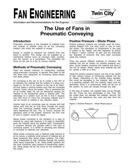
FAN ENGINEERINGInformation and Recommendations for the Eng<strong>in</strong>eer<strong>The</strong> <strong>Use</strong> <strong>of</strong> <strong><strong>Fan</strong>s</strong> <strong>in</strong><strong>Pneumatic</strong> Convey<strong>in</strong>gFE-3300Introduction<strong>Pneumatic</strong> convey<strong>in</strong>g is the transport <strong>of</strong> material fromone location to another us<strong>in</strong>g air as the convey<strong>in</strong>gmedium with which the material is moved.Energy is needed to transport the material from oneplace to another. This energy can be supplied by amechanical method (such as conveyor belts, buckets,etc), fan, blower, or a compressor. This newsletter willfocus on the use <strong>of</strong> a fan to convey material.Methods <strong>of</strong> <strong>Pneumatic</strong> Convey<strong>in</strong>g<strong>The</strong>re are several methods <strong>of</strong> transport<strong>in</strong>g materialsus<strong>in</strong>g pneumatic convey<strong>in</strong>g. In general, they seem to fall<strong>in</strong>to three ma<strong>in</strong> categories: air convey<strong>in</strong>g, dense phase,and dilute phase.Air convey<strong>in</strong>g is the use <strong>of</strong> air to create a th<strong>in</strong> film <strong>of</strong>air between the material and the surface it is be<strong>in</strong>g conveyedon. Air film or air cushion is the use <strong>of</strong> air <strong>in</strong>jectedfrom below a porous surface such that the conveyedmaterial "floats" along the system. This is somewhat likean air hockey table. Air can be directional caus<strong>in</strong>g thematerial to be transported along a desired path. <strong>The</strong>advantage to a system such as this is that it requiresvery little force to move the convey<strong>in</strong>g material and itcan be moved or rotated <strong>in</strong> any direction easily.Another type <strong>of</strong> air convey<strong>in</strong>g uses air nozzles with ballvalves such that the air only flows through the valveswhen the convey<strong>in</strong>g material makes contact with thevalve depress<strong>in</strong>g the ball. This, <strong>of</strong> course, reduces theoperat<strong>in</strong>g costs <strong>of</strong> the system. However, the first cost<strong>of</strong> such a system would be higher.Positive Pressure – Dilute PhasePositive pressure systems are normally used for transport<strong>in</strong>gmaterial from one entry po<strong>in</strong>t to one or moreexit po<strong>in</strong>ts. <strong>The</strong> orientation <strong>of</strong> components <strong>in</strong> this type<strong>of</strong> system is fan, feeder, and then separator as shown<strong>in</strong> Figure 1 below. Cement, fly ash, and dry chemicalsare examples <strong>of</strong> products that have been conveyedus<strong>in</strong>g this method.<strong>The</strong>re are several different methods to <strong>in</strong>troduce thematerial <strong>in</strong>to the air stream for positive pressure systems.Screw feeders compress the material and force it<strong>in</strong>to the air stream. Rotary valves drop material <strong>in</strong>to theair- stream a little at a time.Us<strong>in</strong>g the positive pressure layout, one has to be careful<strong>of</strong> high velocity impact <strong>of</strong> <strong>in</strong>troduc<strong>in</strong>g material <strong>in</strong>to theair stream. Depend<strong>in</strong>g on the material be<strong>in</strong>g handled,this could be damag<strong>in</strong>g to the material. Also, if dustis a potential problem with the material, leaks must beelim<strong>in</strong>ated. S<strong>in</strong>ce it is pressurized, leaks will be out <strong>of</strong>the system, so dust can escape through any leak.In this type <strong>of</strong> system, the material does not go throughthe fan. <strong>The</strong>re are two advantages to this. First, thefan wheel does not damage the material. Second, thefan does not experience any wear and tear from thematerial.Figure 1. Positive Pressure — Dilute Phase LayoutFANFEEDERSEPARATORDense phase convey<strong>in</strong>g is the transport <strong>of</strong> a slug <strong>of</strong>material by us<strong>in</strong>g high pressure (>15 psig) to essentiallypush the material along the desired path. Compressorsor pressure blowers are typically used <strong>in</strong> this type <strong>of</strong>convey<strong>in</strong>g system. It is similar to extrud<strong>in</strong>g and materialis conveyed at relatively low velocities.Dilute phase convey<strong>in</strong>g uses a relatively large amount <strong>of</strong>air to convey a relatively small amount <strong>of</strong> material and atlower pressures than dense phase systems. <strong>The</strong> materialis transported at high velocities through the systemwhile be<strong>in</strong>g suspended <strong>in</strong> air. Dilute phase systems arethe most commonly used method <strong>of</strong> transport<strong>in</strong>g materials.Dilute phase will be the focus for the rema<strong>in</strong>der <strong>of</strong>this article.©2005 Tw<strong>in</strong> <strong>City</strong> <strong>Fan</strong> Companies, Ltd.
Negative Pressure – Dilute PhaseNegative pressure systems are generally used for transport<strong>in</strong>gmaterial from one or more entry po<strong>in</strong>ts to as<strong>in</strong>gle exit po<strong>in</strong>t. <strong>The</strong> configuration <strong>of</strong> components <strong>in</strong> thistype <strong>of</strong> system is feeder, separator, and then fan asshown <strong>in</strong> Figure 2. This type <strong>of</strong> system is almost alwaysused where toxic materials are be<strong>in</strong>g handled becauseany leakage is <strong>in</strong>to the system.Material is fed <strong>in</strong>to a negative pressure system (fandownstream <strong>of</strong> feeder and separator) us<strong>in</strong>g one <strong>of</strong> severalmethods. Mechanical methods may be used, suchas <strong>in</strong> the positive pressure setup. Alternatively, a simplefeeder, such as a duct open<strong>in</strong>g, may be sufficient if thematerial is light enough for the amount <strong>of</strong> vacuum thefan creates. Hopper fed elbows can be useful as anyextra material not collected <strong>in</strong> the air stream will falldown the elbow and can be re-used.<strong>The</strong> negative pressure system is well suited for applicationssuch as unload<strong>in</strong>g rail cars. Another applicationwould be for handl<strong>in</strong>g toxic materials so that any leakagewould be <strong>in</strong>to the system. Gra<strong>in</strong>s, seeds, granularchemicals, and pellets have been successfully transportedus<strong>in</strong>g this method.In this type <strong>of</strong> system, s<strong>in</strong>ce the fan is downstream <strong>of</strong>the separator, the amount <strong>of</strong> material go<strong>in</strong>g through thefan is m<strong>in</strong>imized. <strong>The</strong>refore, the wear and tear on thefan is limited. Another advantage to this type <strong>of</strong> systemis that any leakage is <strong>in</strong>to the system, thereby elim<strong>in</strong>at<strong>in</strong>gdust problems.<strong>The</strong> disadvantage to this type <strong>of</strong> system is that if theload<strong>in</strong>g is high or the length <strong>of</strong> the system is large, thecomponents must be designed for high vacuum. Thisadds cost to the components and must be consideredwhen compar<strong>in</strong>g methods <strong>of</strong> transport.Figure 2. Negative Pressure — Dilute Phase LayoutFEEDERSEPARATORComb<strong>in</strong>ation – Dilute Phase<strong>The</strong> advantages <strong>of</strong> both systems described above maybe obta<strong>in</strong>ed by plac<strong>in</strong>g the fan between the feeder andseparator. However, all the material must pass throughthe fan so wear on the fan and impact <strong>of</strong> the materialgo<strong>in</strong>g through the fan must be considered. This configurationcan be used where there are multiple entry po<strong>in</strong>tsand multiple exit po<strong>in</strong>ts <strong>of</strong> material.FANComb<strong>in</strong>ation dilute phase is where the fan is placedbetween the feeder and separator such that part <strong>of</strong>the system is under vacuum and part is pressurized asshown <strong>in</strong> Figure 3. This is the most common configuration<strong>of</strong> the three dilute phase systems. In this system,material goes through the fan and special fan constructionmay be required. Refer to the <strong>Fan</strong> Modificationssection for more <strong>in</strong>formation on fan design for materialhandl<strong>in</strong>g.Figure 3. Comb<strong>in</strong>ation Dilute PhaseFEEDERFANSEPARATORFeeders and Separators<strong>The</strong>re are many different types <strong>of</strong> feeders that are usedto <strong>in</strong>troduce the material be<strong>in</strong>g conveyed <strong>in</strong>to the airstream. Some common feeders are screw, venturi, andhood feeders.Cyclone separators are typically used to recover the solidsfrom the air stream. Various types <strong>of</strong> filters are alsoused to clean up the air leav<strong>in</strong>g the separators.Material Load<strong>in</strong>g<strong>The</strong> material load<strong>in</strong>g is the ratio <strong>of</strong> the weight flow <strong>of</strong>the material to that <strong>of</strong> the air. For any given material,there is a m<strong>in</strong>imum transport velocity required to conveythe material. <strong>The</strong>refore, the airflow rate will dependon the size <strong>of</strong> the pipe or duct. For any given system,several different pipe/duct sizes may be used, but onlyone will be the most economical.<strong>The</strong>re is quite a range <strong>of</strong> suggested material load<strong>in</strong>gsfor a particular setup, so it is recommended to consultwith a pneumatic convey<strong>in</strong>g expert prior to mak<strong>in</strong>g anycalculations. Typically, a material load<strong>in</strong>g <strong>of</strong> anywherefrom 2:1 to 1:1 or less is acceptable for standard <strong>in</strong>dustrialfans. Pressure blowers may be used up to materialload<strong>in</strong>gs <strong>of</strong> 6:1. Over that, more specialized designs,such as multiple fans or multiple stage blowers, may berequired.Once a pipe size has been selected, the airflow ratecan be calculated based on the m<strong>in</strong>imum transportvelocity <strong>of</strong> the material be<strong>in</strong>g handled.2<strong>Fan</strong> Eng<strong>in</strong>eer<strong>in</strong>g FE-3300
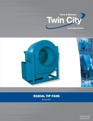
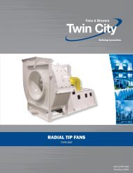
Table 1 lists some materials that are commonly conveyedand the correspond<strong>in</strong>g convey<strong>in</strong>g velocities. In general,materials up to approximately 50 lb/ft 3 can be conveyedwith an air velocity <strong>of</strong> 5000 fpm.Table 1. Common Convey<strong>in</strong>g VelocitiesMATERIALVELOCITYVELOCITYMATERIAL(FPM)(FPM)Paper 5000 Cotton 4000PowderedCoal4000 Wheat 5800Dry VegetablePulp4500 Wool 5000Cement 7000 Oats 4500Sand 7000 Corn 5600Salt 5500 Sugar 6000Sawdust 4000 Flour 3500Losses and <strong>Fan</strong>Performance AdjustmentsBends <strong>in</strong> dilute phase convey<strong>in</strong>g systems are undesirableand should be m<strong>in</strong>imized. <strong>The</strong> bends <strong>in</strong>crease thepressure drop <strong>in</strong> the system. Also, and more importantly,the material go<strong>in</strong>g through a 90-degree bend can impactthe wall <strong>of</strong> the pipe caus<strong>in</strong>g damage to the material aswell as excessive wear on the pipe.Many systems do not have the luxury <strong>of</strong> hav<strong>in</strong>g onlystraight runs <strong>of</strong> duct. <strong>The</strong>refore, to m<strong>in</strong>imize the effect<strong>of</strong> bends, large radius bends may be used. Alternatively,some studies have shown that bl<strong>in</strong>d tees are better than90-degree elbows. <strong>The</strong> material that collects at the teeabsorbs some <strong>of</strong> the impact <strong>of</strong> the material and actslike a cushion to reduce wear on the pipe.<strong>The</strong> additional load<strong>in</strong>g from the material go<strong>in</strong>g throughthe fan requires adjustments to the performance toaccount for the load<strong>in</strong>g. <strong>The</strong>re does not seem to be areliable method to determ<strong>in</strong>e these adjustments, so onlyreasonable estimates can be used. Below are suggestedguidel<strong>in</strong>es for mak<strong>in</strong>g adjustments to horsepower andsystem pressure.<strong>The</strong> horsepower can be adjusted by add<strong>in</strong>g the materialload<strong>in</strong>g factor to one. <strong>The</strong>n multiply the fan horsepowerby this number to get the horsepower with materialload<strong>in</strong>g. Below is an example:Horsepower Sample ProblemACFM = 26,000Material Load<strong>in</strong>g = 19,500 lb/hrInlet Density = 0.05 lb/ft 2BHP @ conditions = 112 BHPMass flow rate <strong>of</strong> air = 26,000 * 0.05 = 1,300 lb/m<strong>in</strong>Mass flow rate <strong>of</strong> material = 19,500/60 = 325 lb/m<strong>in</strong>Material Load<strong>in</strong>g = 325/1,300 = 0.25BHP correction = 1 + material load<strong>in</strong>g = 1.25BHP w/material = 112 x 1.25 = 140 BHP<strong>The</strong> steps to correct the system pressure for materialload<strong>in</strong>g are shown below:1. F<strong>in</strong>d material load<strong>in</strong>g = R (1.25 <strong>in</strong> example above)2. F<strong>in</strong>d SP loss due to acceleration <strong>of</strong> material = R x VPWhere VP = velocity pressure <strong>of</strong> standard airThis may have to be added more than once if thematerial is decelerated and then accelerated aga<strong>in</strong> <strong>in</strong>the system.3. F<strong>in</strong>d SP loss due to lift<strong>in</strong>g material = R x L/69.2Where L = Height <strong>in</strong> feet4. F<strong>in</strong>d SP loss due to friction = F x R x H/69.2Where F = friction factor <strong>of</strong> material aga<strong>in</strong>st steelH = length <strong>of</strong> duct <strong>in</strong> feet5. F<strong>in</strong>d SP loss for elbows (90 degree) = π x F x R x VPAdd this loss for each elbow.6. Add all losses to SP requirement for airflow thoughthe duct.Material Settl<strong>in</strong>gMaterial that settles <strong>in</strong> the horizontal plane <strong>of</strong> a systemis referred to as saltation. In the vertical plane, it isreferred to as chok<strong>in</strong>g. Special care must be taken tom<strong>in</strong>imize settl<strong>in</strong>g. For a particular pipe size and flowrate, the saltation velocity is higher than the chok<strong>in</strong>gvelocity, so design<strong>in</strong>g for the saltation velocity will alsoavoid chok<strong>in</strong>g (Rhodes 2001).It can be difficult to avoid saltation s<strong>in</strong>ce even the slightestseam or ledge can cause material to settle. Materialtends to settle at bends also, so m<strong>in</strong>imiz<strong>in</strong>g bends isrecommended. <strong>The</strong> particles slow down at the bend andthen are re-accelerated after pass<strong>in</strong>g the bend. This slowdown can cause some material to settle. One other wayto help avoid saltation is to remove any leaks becausevelocity will be less downstream <strong>of</strong> leaks.At the same time, one does not want to select a velocitymuch higher than needed just to avoid settl<strong>in</strong>g. <strong>The</strong>additional velocity would be detrimental to the system bycaus<strong>in</strong>g <strong>in</strong>creased friction, wear, and operat<strong>in</strong>g costs.<strong>Fan</strong> SelectionOnce the calculations for the system have been performedand the appropriate pipe size has been selectedbased on material be<strong>in</strong>g conveyed and system resistance,the fan operat<strong>in</strong>g po<strong>in</strong>t is a simple calculation.<strong>The</strong> required flow rate <strong>of</strong> the fan is simply the velocitymultiplied by the area.<strong>Fan</strong> Considerations forMaterial Handl<strong>in</strong>gIf the material be<strong>in</strong>g conveyed will be go<strong>in</strong>g throughthe fan, special considerations must be given to thefan design. Several factors must be considered <strong>in</strong> orderto select the appropriate fan for the application be<strong>in</strong>gconsidered.<strong>The</strong> fan blade type selection is very important becauseone does not want to select a blade type that is proneto collect<strong>in</strong>g material. Backward curved and airfoil bladesare efficient, but are better suited for clean air applicationsbecause they <strong>of</strong>ten collect material on the blades.Radial blades are better suited for material handl<strong>in</strong>gapplications. Backward <strong>in</strong>cl<strong>in</strong>ed blades and blades thathave a radial tip have also been used successfully <strong>in</strong>certa<strong>in</strong> material handl<strong>in</strong>g applications.<strong>Fan</strong> speed is also important <strong>in</strong> select<strong>in</strong>g a fan for materialhandl<strong>in</strong>g. <strong>The</strong> operat<strong>in</strong>g speed should be m<strong>in</strong>imizedas much as possible. High-speed fans with high tipspeeds create higher velocities that correspond directlyto the level <strong>of</strong> erosion and impact on the fan and systemcomponents.3<strong>Fan</strong> Eng<strong>in</strong>eer<strong>in</strong>g FE-3300
<strong>The</strong> fan should be selected with the critical speed significantlyhigher than the operat<strong>in</strong>g speed. A good rule<strong>of</strong> thumb for material handl<strong>in</strong>g fans is to keep the rigidsupport critical speed at least 1.5 times greater than theoperat<strong>in</strong>g speed.Special materials may be required to resist corrosion,abrasion, and impact depend<strong>in</strong>g on the material be<strong>in</strong>ghandled. In some applications, l<strong>in</strong>ers are added to thefan wheel at locations where the most abrasion willoccur. <strong>The</strong>se l<strong>in</strong>ers can then be replaced periodicallywithout hav<strong>in</strong>g to replace the entire wheel. <strong>The</strong> level<strong>of</strong> abrasion <strong>of</strong> the material will determ<strong>in</strong>e the level <strong>of</strong>erosion protection needed. Some applications may onlyrequire a special coat<strong>in</strong>g, while others may requirespecial material l<strong>in</strong>ers to be <strong>in</strong>stalled on the fan wheeland/or hous<strong>in</strong>g.Special coat<strong>in</strong>gs may also be required to resist corrosionor to make clean<strong>in</strong>g easier. Oversized access doors maybe used to make ma<strong>in</strong>tenance and clean<strong>in</strong>g easier toaccomplish. Special construction <strong>of</strong> the hous<strong>in</strong>g, knownas sw<strong>in</strong>g-out and clamshell, allow for easy access tothe fan components for clean<strong>in</strong>g and ma<strong>in</strong>tenance. Insw<strong>in</strong>g-out construction, the fan wheel, shaft, bear<strong>in</strong>gs,and motor are mounted on a door. <strong>The</strong> door can beopened for easy clean<strong>in</strong>g <strong>of</strong> fan components withoutremov<strong>in</strong>g ductwork.Shaft seals may be required to resist materials fromleak<strong>in</strong>g out around the fan shaft.If the material be<strong>in</strong>g handled is explosive or flammable,spark resistant construction is required. AMCA Standard99 specifies Type A, B, and C spark construction, whichare available for many fan designs. If materials such ascoal are be<strong>in</strong>g transported, the National Fire ProtectionAssociation requires the fan hous<strong>in</strong>g design to withstandan explosion.If high temperatures are present, such as an applicationwhere pneumatic convey<strong>in</strong>g and dry<strong>in</strong>g are bothbe<strong>in</strong>g performed, high temperature construction may berequired. This may <strong>in</strong>clude shaft seals, shaft coolers,motor heat shields, special materials, and/or <strong>in</strong>sulatedhous<strong>in</strong>gs.Special consideration may need to be given to bear<strong>in</strong>gselection. <strong>The</strong> fan arrangement should be selected suchthat the bear<strong>in</strong>gs are out <strong>of</strong> the air stream. Also, highercapacity bear<strong>in</strong>gs may need to be used to allow forloads created by the material impact<strong>in</strong>g on the impeller.<strong>Fan</strong> orientation can also be important <strong>in</strong> material handl<strong>in</strong>gapplications. In centrifugal fans, bottom horizontalor bottom-angular-up discharges are preferred. In otherconfigurations, if material settles <strong>in</strong> the fan hous<strong>in</strong>g,it drops to the bottom and stays there. With bottomhorizontal or angular up discharges, material tends notto settle due to high velocities at the bottom <strong>of</strong> thehous<strong>in</strong>g.Conclusion<strong>Pneumatic</strong> convey<strong>in</strong>g is one <strong>of</strong> several methods <strong>of</strong> mov<strong>in</strong>gmaterial from one location to another. Each <strong>in</strong>dividualcase must be evaluated for multiple methods <strong>of</strong> transportbefore decid<strong>in</strong>g on the best method. <strong>Pneumatic</strong>convey<strong>in</strong>g, when designed correctly, can provide manybenefits over other methods <strong>of</strong> material transport. <strong>The</strong>space required for a pneumatic convey<strong>in</strong>g system istypically less than a mechanical method <strong>of</strong> transport.It can be modified without significant cost. Also, theamount <strong>of</strong> material lost can be m<strong>in</strong>imized.Select<strong>in</strong>g the fan for pneumatic convey<strong>in</strong>g can rangefrom easy to very <strong>in</strong>volved depend<strong>in</strong>g on the location<strong>of</strong> the fan <strong>in</strong> the system. Special construction maybe required to handle the additional load<strong>in</strong>g and wearcaused by the material be<strong>in</strong>g handled. If you are <strong>in</strong>need <strong>of</strong> help <strong>in</strong> determ<strong>in</strong><strong>in</strong>g what type <strong>of</strong> fan to useor if special construction is required, consult your fanmanufacturer.References1. <strong>Pneumatic</strong> Transport <strong>of</strong> Powders by Mart<strong>in</strong> Rhodes,20012. Bulk Materials Handl<strong>in</strong>g Handbook by JacobFruchtbaum, 1988Tw<strong>in</strong> city fan & blower | www.tcf.com5959 Trenton Lane N | M<strong>in</strong>neapolis, MN 55442 | Phone: 763-551-7600 | Fax: 763-551-7601