CMOS single-chip 8-bit MCU with 12-bit A/D converter ... - abov.co.kr
CMOS single-chip 8-bit MCU with 12-bit A/D converter ... - abov.co.kr
CMOS single-chip 8-bit MCU with 12-bit A/D converter ... - abov.co.kr

You also want an ePaper? Increase the reach of your titles
YUMPU automatically turns print PDFs into web optimized ePapers that Google loves.
ABOV Semi<strong>co</strong>nductor Co., Ltd.MC96F6432SRevision historyVersion Date Revision list0.0 20<strong>12</strong>.08.24 Published this book.1.0 2013.05.22 Revised this book.Version 1.0Published by FAE team2013 ABOV Semi<strong>co</strong>nductor Co. Ltd. all rights reserved.Additional information of this manual may be served by ABOV Semi<strong>co</strong>nductor offices in Korea or distributors.ABOV Semi<strong>co</strong>nductor reserves the right to make changes to any information here in at any time <strong>with</strong>out notice.The information, diagrams and other data in this manual are <strong>co</strong>rrect and reliable;however, ABOV Semi<strong>co</strong>nductor is in no way responsible for any violations of patents or other rights of the thirdparty generated by the use of this manual.2
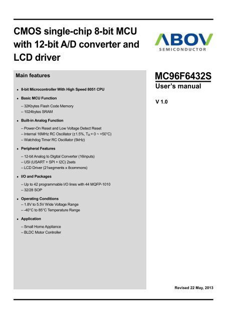
MC96F6432SABOV Semi<strong>co</strong>nductor Co., Ltd.1 Overview1.1. DescriptionThe MC96F6432S is an advanced <strong>CMOS</strong> 8-<strong>bit</strong> micro<strong>co</strong>ntroller <strong>with</strong> 32Kbytes of FLASH. This is powerfulmicro<strong>co</strong>ntroller which provides a highly flexible and <strong>co</strong>st effective solution to many embedded <strong>co</strong>ntrol applications. Thisoffers the following features: 32Kbytes of FLASH, 256bytes of IRAM, 768bytes of XRAM, general purpose I/O, basicinterval timer, watchdog timer, 8/16-<strong>bit</strong> timer/<strong>co</strong>unter, 16-<strong>bit</strong> PPG output, 8-<strong>bit</strong> PWM output, 10-<strong>bit</strong> PWM output, watchtimer, buzzer driving port, SPI, USI, <strong>12</strong>-<strong>bit</strong> A/D <strong><strong>co</strong>nverter</strong>, LCD driver, on-<strong>chip</strong> POR, LVR, LVI, on-<strong>chip</strong> oscillator andclock circuitry. The MC96F6432S also supports power saving modes to reduce power <strong>co</strong>nsumption.Device Name FLASH XRAM IRAM ADC I/O PORT PackageMC96F6432SQ16inputs 42 44 MQFPMC96F6332SD 32Kbytes 768bytes 256bytes <strong>12</strong>inputs 30 32 SOPMC96F6332SM 11inputs 26 28 SOPTable 1.1Ordering Information of MC96F6432S3
ABOV Semi<strong>co</strong>nductor Co., Ltd.MC96F6432S1.2 Features• CPU8-<strong>bit</strong> CISC <strong>co</strong>re (M8051, 2 clocks per cycle)• ROM (FLASH) Capacity32Kbytes Flash <strong>with</strong> self-read and write capabilityIn-System Programming(ISP)Endurance : 100,000times• 256bytes IRAM• 768bytes XRAM(27bytes including LCD display RAM)• General Purpose I/O (GPIO)Normal I/O : 9ports (P0[2:0], P5[5:0])LCD shared I/O : 33ports (P0[7:3], P1, P2, P3, P4)• Timer/CounterBasic Interval Timer (BIT) 8-<strong>bit</strong> × 1-chWatch Dog Timer (WDT) 8-<strong>bit</strong> × 1-ch5kHz internal RC oscillator8-<strong>bit</strong> × 1-ch (T0), 16-<strong>bit</strong> × 2-ch (T1/T2)8-<strong>bit</strong> × 2-ch (T3/T4) or 16-<strong>bit</strong> × 1-ch (T3)• Programmable Pulse GenerationPulse generation (by T1/T2)8-<strong>bit</strong> PWM (by T0)6-ch 10-<strong>bit</strong> PWM for Motor (by T4)• Watch Timer (WT)3.91ms/0.25s/0.5s/1s /1min interval at 32.768kHz• Buzzer8-<strong>bit</strong> × 1-ch• SPI 28-<strong>bit</strong> × 1-ch• USI0/1 (UART + SPI + I2C)8-<strong>bit</strong> UART × 2-ch, 8-<strong>bit</strong> SPI × 2-ch and I2C × 2-ch• <strong>12</strong>-<strong>bit</strong> A/D Converter16 Input channels• LCD Driver21segments and 8<strong>co</strong>mmon terminalsInternal or external resistor biasTwo Internal Resistors Selectable1/2, 1/3, 1/4, 1/5, 1/6 and 1/8 duty selectableResistor Bias and 16-step <strong>co</strong>ntrast <strong>co</strong>ntrol• Power On ResetReset release level (1.4V)• Low Voltage Reset14 levels detect(1.60/ 2.00/ 2.10/ 2.20/ 2.32/ 2.44/ 2.59/ 2.75/ 2.93/3.14/ 3.38/ 3.67/ 4.00/ 4.40V)• Low Voltage Indicator13 levels detect(2.00 / 2.10/ 2.20/ 2.32/ 2.44/ 2.59/ 2.75/ 2.93/ 3.14/3.38/ 3.67/ 4.00/ 4.40V)• Interrupt SourcesExternal Interrupts(EXINT0~7, EINT8, EINT10, EINT11, EINT<strong>12</strong>) (<strong>12</strong>)Timer(0/1/2/3/4) (5)WDT (1)BIT (1)WT (1)SPI 2 (1)USI0/1 (6)ADC (1)• Internal RC OscillatorInternal RC frequency: 16MHz ±1.5% (T A = 0 ~ +50°C)• Power Down ModeSTOP, IDLE mode• Operating Voltage and Frequency1.8V~ 5.5V (@32 ~ 38kHz <strong>with</strong> Crystal)1.8V~ 5.5V (@0.4 ~ 4.2MHz <strong>with</strong> Crystal)2.7V~ 5.5V (@0.4 ~ 10.0MHz<strong>with</strong> Crystal)3.0V~ 5.5V (@0.4 ~ <strong>12</strong>.0MHz <strong>with</strong> Crystal)1.8V~ 5.5V (@0.5 ~ 8.0MHz <strong>with</strong> Internal RC)2.0V~ 5.5V (@0.5 ~ 16.0MHz <strong>with</strong> Internal RC)Voltage dropout <strong><strong>co</strong>nverter</strong> included for <strong>co</strong>re• Minimum Instruction Execution Time<strong>12</strong>5ns (@16MHz main clock)61us (@t 32.768kHz sub clock)• Operating Temperature–40 ~ +85• Oscillator Type0.4 - <strong>12</strong>MHz Crystal or Ceramic for main clock32.768kHz Crystal for sub clockPackage Type44 MQFP-101032 SOP28 SOPPb-free package4
MC96F6432SABOV Semi<strong>co</strong>nductor Co., Ltd.1.3 Development tools1.3.1 CompilerABOV Semi<strong>co</strong>nductor does not provide <strong>co</strong>mpiler. It is re<strong>co</strong>mmended that you <strong>co</strong>nsult a <strong>co</strong>mpier provider.The MC96F6432S <strong>co</strong>re is Mentor 8051, and the ROM size is smaller than 64Kbytes.Therefore, developer can use thestandard 8051 <strong>co</strong>mpiler from other providers.1.3.2 OCD(On-<strong>chip</strong> debugger) emulator and debuggerThe OCD (On Chip Debug) emulator supports ABOV Semi<strong>co</strong>nductor’s 8051 series <strong>MCU</strong> emulation.The OCD interfaceuses two-wire <strong>co</strong>nnection between PC and <strong>MCU</strong> which is attached to user’s system. The OCD can read or change thevalue of <strong>MCU</strong> internal memory and I/O peripherals. And the OCD also <strong>co</strong>ntrols <strong>MCU</strong> internal debugging logic, it meansOCD <strong>co</strong>ntrols emulation, step run, monitoring, etc.The OCD debugger program works on Microsoft-Windows NT, 2000, XP, Vista (32-<strong>bit</strong>) operating system.If you want tosee more details, please refer to OCD debugger manual. You can download debugger S/W and manual from our website(http://www.<strong>abov</strong>.<strong>co</strong>.<strong>kr</strong>).Connection:DSCL (MC96F6432 P01 port)DSDA (MC96F6432 P00 port)NOTE)1. MC96F6432S does not support the OCD function. MC96F6432 should be used for debugging.OCD <strong>co</strong>nnector diagram: Connect OCD <strong>with</strong> user system<strong>12</strong> User VCC3 45 67 8User GNDDSCLDSDA910Figure 1.1debugger and pin descriptionSubject MC96F6432S MC96F6432 (Evaluation <strong>chip</strong>)Internal LCD bias dividing resistor(Chapter 11.15 – LCD driver)Full-flash erase mode method(Chapter 15 – Flash memory)60kΩ and <strong>12</strong>0kΩ selectableAdded the IRSEL <strong>bit</strong> in the LCDCRL registerAdded LCD <strong>co</strong>ntrast formula <strong>with</strong> <strong>12</strong>0kΩSector erase mode60k onlySector and byte erase modeTable 1.2Difference between MC96F6432S and evaluation <strong>chip</strong> (MC96F6432)5
ABOV Semi<strong>co</strong>nductor Co., Ltd.MC96F6432S1.3.3 ProgrammerSingle programmer:PGMplus USB: It programs <strong>MCU</strong> device directly.Figure 1.4PGMplusUSB(Single writer)Standalone PGMplus:It programs <strong>MCU</strong> device directly.Figure 1.5Standalone PGMplus(Single writer)6
MC96F6432SABOV Semi<strong>co</strong>nductor Co., Ltd.OCD emulator:It can write <strong>co</strong>de to <strong>MCU</strong> device too, because OCD debugger supports ISP (In System Programming).It does notrequire additional H/W, except developer’s target system.Gang programmer:It programs 8 <strong>MCU</strong> devices at once.So, it is mainly used in mass production factory.Gang programmer is standalone type, it means it does not require host PC, after a program is downloaded from hostPC to Gang programmer.Figure 1.6StandAlone Gang8 (for Mass Production)7
ABOV Semi<strong>co</strong>nductor Co., Ltd.MC96F6432S1.4 MTP programming1.4.1 OverviewThe program memory of MC96F6432S is MTP Type. This flash is accessed by serial data format. There are fourpins(DSCL, DSDA, VDD, and VSS) for programming/reading the flash.Pin nameMain <strong>chip</strong>pin nameI/ODuring programmingDescriptionDSCL P01 I Serial clock pin. Input only pin.DSDA P00 I/OSerial data pin. Output port when reading and input port when programming.Can be assigned as input/push-pull output port.VDD, VSS VDD, VSS - Logic power supply pin.Table 1.3Descriptions of pins which are used to programming/reading the Flash1.4.2 On-Board programmingThe MC96F6432S needs only four signal lines including VDD and VSS pins for programming FLASH <strong>with</strong> serial<strong>co</strong>mmunication proto<strong>co</strong>l. Therefore the on-board programming is possible if the programming signal lines are ready atthe PCB of application board is designed.1.4.2.1 Circuit Design GuideAt the FLASH programming, the programming tool needs 4 signal lines that areDSCL, DSDA, VDD, and VSS. Whenyou design the PCB circuits, you should <strong>co</strong>nsider the usage of these signal lines for the on-board programming.Please be careful to design the related circuit of these signal pins because rising/falling timing of DSCL and DSDA isvery important for proper programming.8
MC96F6432SABOV Semi<strong>co</strong>nductor Co., Ltd.PGM plus USB, StandAlone PGM plus, StandAlone Gang8DSCL(I)R1 (2k ~ 5k )To application circuitDSDA(I/O)R2 (2k ~ 5k )To application circuitVDDVSSNOTE)1. In on-board programming mode, very high-speed signal will be provided to pin DSCL and DSDA.And it will cause some damages to the application circuits <strong>co</strong>nnected to DSCL or DSDA port if theapplication circuit is designed as high speed response such as relay <strong>co</strong>ntrol circuit. If possible, theI/O <strong>co</strong>nfiguration of DSDA, DSCL pins had better be set to input mode.2. The value of R1 and R2 is re<strong>co</strong>mmended value. It varies <strong>with</strong> circuit of system.Figure 1.7PCB design guide for on board programming9
ABOV Semi<strong>co</strong>nductor Co., Ltd.MC96F6432S2 Block diagramFlash32KBCOREM8051XRAM768BIRAM256BGeneral purpose I/O9 ports normal I/O33 ports LCD shared I/OISPIn-system programmingWatchdog timer1 channel, 8-<strong>bit</strong>5kHz, internal RC OSCBasic interval timer1 channel, 8-<strong>bit</strong>Power <strong>co</strong>ntrolPower on resetLow voltage resetLow voltage indicatorPower down modeClock generator16MHz, Internal RC OSC<strong>12</strong>MHz, Crystal OSC32.768kHz, Crystal OSCTimer / Counter1 channel, 8-<strong>bit</strong>2 channels, 16-<strong>bit</strong>2 channels, 8-<strong>bit</strong>or 1 channel, 16-<strong>bit</strong>LCD driver21 segmentsBuzzer1 channel, 8-<strong>bit</strong>UART2 channels, 8-<strong>bit</strong>ADC16 Input channels, <strong>12</strong>-<strong>bit</strong>PWM6 channelsSPI3 channels, 8-<strong>bit</strong>I2C2 channels, 8-<strong>bit</strong>Figure 2.1Block diagrom of MC96F6432S10
MC96F6432SABOV Semi<strong>co</strong>nductor Co., Ltd.3 Pin assignmentP03/SEG26/AN1/EINT1/PWM4ABP02/AN0/AVREF/EINT0/T4O/PWM4AAP01/T3O/DSCLP00/EC3/DSDAVDDVSSP50/XOUTP51/XINP52/EINT8/EC0/BLNKP53/SXIN/T0O/PWM0OP54/SXOUT/EINT10P55/RESETBP40/VLC3/RXD0/SCL0/MISO0P41/VLC2/TXD0/SDA0/MOSI0P42/VLC1/SCK0P43/VLC0/SS0P37/COM0P36/COM1P35/COM2/SEG0P34/COM3/SEG1P33/COM4/SEG2P32/COM5/SEG3<strong>12</strong>3456789101144434241403938373635MC96F6432SQ(44MQFP-1010)343332313029282726252423P04/SEG25/AN2/EINT2/PWM4BAP05/SEG24/AN3/EINT3/PWM4BBP06/SEG23/AN4/EINT4/PWM4CAP07/SEG22/AN5/EINT5/PWM4CBP17/SEG21/AN6/EINT6/SS2P16/SEG20/AN7/EINT7/SCK2P15/SEG19/AN8/MISO2P14/SEG18/AN9/MOSI2P13/SEG17/AN10/EC1/BUZOP<strong>12</strong>/SEG16/AN11/EINT11/T1O/PWM1OP11/SEG15/AN<strong>12</strong>/EINT<strong>12</strong>/T2O/PWM2O222<strong>12</strong>019181716151413<strong>12</strong>P10/SEG14/AN13/RXD1/SCL1/MISO1P20/SEG13/AN14/TXD1/SDA1/MOSI1P21/SEG<strong>12</strong>/AN15/SCK1P22/SEG11/SS1P23/SEG10P24/SEG9P25/SEG8P26/SEG7P27/SEG6P30/COM7/SEG5P31/COM6/SEG4NOTE)1. The programmer (PGMplus, Gang8) uses P0[1:0] pin as DSCL, DSDA.Figure 3.1MC96F6432SQ 44MQFP-1010 pin assignment11
ABOV Semi<strong>co</strong>nductor Co., Ltd.MC96F6432SVSSP50/XOUTP51/XINP52/EINT8/EC0/BLNKP53/SXIN/T0O/PWM0OP54/SXOUT/EINT10P55/RESETBP40/VLC3/RXD0/SCL0/MISO0P41/VLC2/TXD0/SDA0/MOSI0P42/VLC1/SCK0P33/COM4/SEG2P32/COM5/SEG3P31/COM6/SEG4P30/COM7/SEG5P27/SEG6P26/SEG7<strong>12</strong>34567891011<strong>12</strong>13141516MC96F6332SD(32-SOP)32313029282726252423222<strong>12</strong>0191817VDDP00/EC3/DSDAP01/T3O/DSCLP02/AN0/AVREF/EINT0/T4O/PWM4AAP03/SEG26/AN1/EINT1/PWM4ABP04/SEG25/AN2/EINT2/PWM4BAP05/SEG24/AN3/EINT3/PWM4BBP06/SEG23/AN4/EINT4/PWM4CAP07/SEG22/AN5/EINT5/PWM4CBP13/SEG17/AN10/EC1/BUZOP<strong>12</strong>/SEG16/AN11/EINT11/T1O/PWM1OP11/SEG15/AN<strong>12</strong>/EINT<strong>12</strong>/T2O/PWM2OP10/SEG14/AN13/RXD1/SCL1/MISO1P20/SEG13/AN14/TXD1/SDA1/MOSI1P21/SEG<strong>12</strong>/AN15/SCK1P22/SEG11/SS1NOTE)1. The programmer (PGMplus, Gang) uses P0[1:0] pin as DSCL, DSDA.2. The P14-P17, P23-P25, P34-P37 and P43 pins should be selected as a push-pull output or an input<strong>with</strong> pull-up resistor by software <strong>co</strong>ntrol when the 32-pin package is used.Figure 3.2MC96F6332SD 32SOP pin assignmentVSSP50/XOUTP51/XINP52/EINT8/EC0/BLNKP53/SXIN/T0O/PWM0OP54/SXOUT/EINT10P55/RESETBP40/VLC3/RXD0/SCL0/MISO0P41/VLC2/TXD0/SDA0/MOSI0P42/VLC1/SCK0P33/COM4/SEG2P32/COM5/SEG3P31/COM6/SEG4P30/COM7/SEG5<strong>12</strong>34567891011<strong>12</strong>1314MC96F6332SM(28-SOP)282726252423222<strong>12</strong>01918171615VDDP00/EC3/DSDAP01/T3O/DSCLP02/AN0/AVREF/EINT0/T4O/PWM4AAP03/SEG26/AN1/EINT1/PWM4ABP04/SEG25/AN2/EINT2/PWM4BAP05/SEG24/AN3/EINT3/PWM4BBP06/SEG23/AN4/EINT4/PWM4CAP07/SEG22/AN5/EINT5/PWM4CBP<strong>12</strong>/SEG16/AN11/EINT11/T1O/PWM1OP11/SEG15/AN<strong>12</strong>/EINT<strong>12</strong>/T2O/PWM2OP10/SEG14/AN13/RXD1/SCL1/MISO1P20/SEG13/AN14/TXD1/SDA1/MOSI1P21/SEG<strong>12</strong>/AN15/SCK1NOTE)1. The programmer (PGMplus, Gang) uses P0[1:0] pin as DSCL, DSDA.2. The P13-P17, P22-P27, P34-P37 and P43 pins should be selected as a push-pull output or an input<strong>with</strong> pull-up resistor by software <strong>co</strong>ntrol when the 32-pin package is used.Figure 3.3MC96F6332SM 28SOP pinassignment<strong>12</strong>
MC96F6432SABOV Semi<strong>co</strong>nductor Co., Ltd.4 Package DiagramFigure 4.144-Pin MQFP Package13
ABOV Semi<strong>co</strong>nductor Co., Ltd.MC96F6432SFigure 4.232-Pin SOP Package14
MC96F6432SABOV Semi<strong>co</strong>nductor Co., Ltd.Figure 4.328-Pin SOP Package15
ABOV Semi<strong>co</strong>nductor Co., Ltd.MC96F6432S5 Pin DescriptionPINNameP00P01P02P03P04P05P06P07P10P11P<strong>12</strong>P13P14P15P16P17P20P21P22P23P24P25P26P27P30P31P32P33P34P35P36P37P40P41P42P43Table 5.1I/O Function @RESET Shared <strong>with</strong>I/OI/OI/OI/OI/OPort 0 is a <strong>bit</strong>-programmable I/O port which can be<strong>co</strong>nfigured as a Schmitt-trigger input, a push-pulloutput, or an open-drain output.A pull-up resistor can be specified in 1-<strong>bit</strong> unit.Port 1 is a <strong>bit</strong>-programmable I/O port which can be<strong>co</strong>nfigured as a Schmitt-trigger input, a push-pulloutput, or an open-drain output.A pull-up resistor can be specified in 1-<strong>bit</strong> unit.The P14 – P17 are not in the 32-pin package. TheP13 – P17 are not in the 28-pin package.Port 2 is a <strong>bit</strong>-programmable I/O port which can be<strong>co</strong>nfigured as an input, a push-pull output, or anopen-drain output.A pull-up resistor can be specified in 1-<strong>bit</strong> unit.The P23 – P25 are not in the 32-pin package.The P22 – P27 are not in the 28-pin package.Port 3 is a <strong>bit</strong>-programmable I/O port which can be<strong>co</strong>nfigured as an input, a push-pull output.A pull-up resistor can be specified in 1-<strong>bit</strong> unit.The P34 – P37 are only in the 44-pin package.Port 4 is a <strong>bit</strong>-programmable I/O port which can be<strong>co</strong>nfigured as an input, a push-pull output, or anopen-drain output.A pull-up resistor can be specified in 1-<strong>bit</strong> unit.The P43 is only in the 44-pin package.Normal Pin DescriptionInputInputInputInputInputEC3/DSDAT3O/DSCLAN0/AVREF/EINT0/T4O/PWM4AASEG26/AN1/EINT1/PWM4ABSEG25/AN2/EINT2/PWM4BASEG24/AN3/EINT3/PWM4BBSEG23/AN4/EINT4/PWM4CASEG22/AN5/EINT5/PWM4CBSEG14/AN13/RXD1/SCL1/MISO1SEG15/AN<strong>12</strong>/EINT<strong>12</strong>/T2O/PWM2OSEG16/AN11/EINT11/T1O/PWM1OSEG17/AN10/EC1/BUZOSEG18/AN9/MOSI2SEG19/AN8/MISO2SEG20/AN7/EINT7/SCK2SEG21/AN6/EINT6/SS2SEG13/AN14/TXD1/SDA1/MOSI1SEG<strong>12</strong>/AN15/SCK1SEG11/SS1SEG10SEG9SEG8SEG7SEG6COM7/SEG5COM6/SEG4COM5/SEG3COM4/SEG2COM3/SEG1COM2/SEG0COM1COM0VLC3/RXD0/SCL0/MISO0VLC2/TXD0/SDA0/MOSI0VLC1/SCK0VLC0/SS016
MC96F6432SABOV Semi<strong>co</strong>nductor Co., Ltd.PINNameP50P51P52P53P54P55I/O Function @RESET Shared <strong>with</strong>I/OPort 5 is a <strong>bit</strong>-programmable I/O port which can be<strong>co</strong>nfigured as a Schmitt-trigger input or a push-pulloutput.A pull-up resistor can be specified in 1-<strong>bit</strong> unit.InputXOUTXINEINT8/EC0/BLNKSXIN/T0O/PWM0OSXOUT/EINT10RESETBEINT0 I/O External interrupt input and Timer 3 capture input Input P02/AN0/AVREF/T4O/PWM4AAEINT1 I/O External interrupt input and Timer 4 capture input Input P03/SEG26/AN1/PWM4ABEINT2EINT3EINT4EINT5EINT6EINT7EINT8I/O External interrupt inputs InputP04/SEG25/AN2/PWM4BAP05/SEG24/AN3/PWM4BBP06/SEG23/AN4/PWM4CAP07/SEG22/AN5/PWM4CBP17/SEG21/AN6/SS2P16/SEG20/AN7/SCK2P52/EC0/BLNKEINT10 I/O External interrupt input and Timer 0 capture input Input P54/SXOUTEINT11 I/O External interrupt input and Timer 1 capture input Input P<strong>12</strong>/SEG16/AN11/T1O/PWM1OEINT<strong>12</strong> I/O External interrupt input and Timer 2 capture input Input P11/SEG15/AN<strong>12</strong>/T2O/PWM2OT0O I/O Timer 0 interval output Input P53/SXIN/PWM0OT1O I/O Timer 1 interval output Input P<strong>12</strong>/SEG16/AN11/EINT11/PWM1OT2O I/O Timer 2 interval output Input P11/SEG15/AN<strong>12</strong>/EINT<strong>12</strong>/PWM2OT3O I/O Timer 3 interval output Input P01/DSCLT4O I/O Timer 4 interval output Input P02/AN0/AVREF/EINT0/PWM4AAPWM0O I/O Timer 0 PWM output Input P53/SXIN/T0OPWM1O I/O Timer 1 PWM output Input P<strong>12</strong>/SEG16/AN11/EINT11/T1OPWM2O I/O Timer 2 PWM output Input P11/SEG15/AN<strong>12</strong>/EINT<strong>12</strong>/T2OPWM4AAPWM4ABPWM4BAPWM4BBPWM4CAPWM4CBI/O Timer 4 PWM outputs InputP02/AN0/AVREF/EINT0/T4OP03/SEG26/AN1/EINT1P04/SEG25/AN2/EINT2P05/SEG24/AN3/EINT3P06/SEG23/AN4/EINT4P07/SEG22/AN5/EINT5BLNK I/O External sync signal input for 6-ch PWMs Input P52/EINT8/EC0EC0 I/O Timer 0 event <strong>co</strong>unt input Input P52/EINT8/BLNKEC1 I/O Timer 1 event <strong>co</strong>unt input Input P13/SEG17/AN10EC3 I/O Timer 3 event <strong>co</strong>unt input Input P00/DSDATable 5.2Normal Pin Description (<strong>co</strong>ntinue)17
ABOV Semi<strong>co</strong>nductor Co., Ltd.MC96F6432SPINNameI/O Function @RESET Shared <strong>with</strong>BUZO I/O Buzzer signal output Input P13/SEG17/AN10/EC1SCK0 I/O Serial 0 clock input/output Input P42/VLC1SCK1 I/O Serial 1 clock input/output Input P21/SEG<strong>12</strong>/AN15SCK2 I/O Serial 2 clock input/output Input P16/SEG20/AN7/EINT7MOSI0 I/O SPI 0 master output, slave input Input P41/VLC2/TXD0/SDA0MOSI1 I/O SPI 1 master output, slave input Input P20/SEG13/AN14/TXD1/SDA1MOSI2 I/O SPI 2 master output, slave input Input P14/SEG18/AN9MISO0 I/O SPI 0 master input, slave output Input P40/VLC3/RXD0/SCL0MISO1 I/O SPI 1 master input, slave output Input P10/SEG14/AN13/RXD1/SCL1MISO2 I/O SPI 2 master input, slave output Input P15/SEG19/AN8SS0 I/O SPI 0 slave select input Input P43/VLC0SS1 I/O SPI 1 slave select input Input P22/SEG11SS2 I/O SPI 2 slave select input Input P17/SEG21/AN6/EINT6TXD0 I/O UART 0 data output Input P41/VLC2/SDA0/MOSI0TXD1 I/O UART 1 data output Input P20/SEG13/AN14/SDA1/MOSI1RXD0 I/O UART 0 data input Input P40/VLC3/SCL0/MISO0RXD1 I/O UART 1 data input Input P10/SEG14/AN13/SCL1/MISO1SCL0 I/O I2C 0 clock input/output Input P40/VLC3/RXD0/MISO0SCL1 I/O I2C 1 clock input/output Input P10/SEG14/AN13/RXD1/MISO1SDA0 I/O I2C 0 data input/output Input P41/VLC2/TXD0/MOSI0SDA1 I/O I2C 1 data input/output Input P20/SEG13/AN14/TXD1/MOSI1AVREF I/O A/D <strong><strong>co</strong>nverter</strong> reference voltage Input P02/AN0/EINT0/T4O/PWM4AAAN0AN1AN2AN3AN4AN5AN6AN7AN8AN9AN10AN11AN<strong>12</strong>AN13AN14AN15I/O A/D <strong><strong>co</strong>nverter</strong> analog input channels InputP02/AVREF/EINT0/T4O/PWM4AAP03/SEG26/EINT1/PWM4ABP04/SEG25/EINT2/PWM4BAP05/SEG24/EINT3/PWM4BBP06/SEG23/EINT4/PWM4CAP07/SEG22/EINT5/PWM4CBP17/SEG21/EINT6/SS2P16/SEG20/EINT7/SCK2P15/SEG19/MISO2P14/SEG18/MOSI2P13/SEG17/EC1P<strong>12</strong>/SEG16/EINT11/T1O/PWM1OP11/SEG15/EINT<strong>12</strong>/T2O/PWM2OP10/SEG14/RXD1/SCL1/MISO1P20/SEG13/TXD1/SDA1/MOSI1P21/SEG<strong>12</strong>/SCK1Table 5.3Normal Pin Description (<strong>co</strong>ntinue)18
ABOV Semi<strong>co</strong>nductor Co., Ltd.MC96F6432SPINNameI/O Function @RESET Shared <strong>with</strong>RESETB I/OSystem reset pin <strong>with</strong> a pull-up resistor when it isselected as the RESETB by CONFIGURE OPTIONInput P55DSDA I/O In-system programming data input/output Input P00/EC3DSCL I/O In-system programming clock input Input P01/T3OXINXOUTSXINSXOUTVDD,VSSI/O Main oscillator pins InputI/O Sub oscillator pins Input– Power input pins – –P51P50P53/T0O/PWM0OP54/EINT10Table 5.5Normal Pin Description (<strong>co</strong>ntinue)NOTE)1. The P14–P17, P23–P25, P34–P37, and P43 are not in the 32-pin package.2. The P13–P17, P22–P27, P34–P37, and P43 are not in the 28-pin package.3. The P55/RESETB pin is <strong>co</strong>nfigured as one of the P55 and RESETB pin by the “CONFIGURE OPTION.”4. If the P00/EC3/DSDA and P01/T3O/DSCL pins are <strong>co</strong>nnected to the programmer during power-on reset,the pins are automatically <strong>co</strong>nfigured as In-system programming pins.5. The P00/EC3/DSDA and P01/T3O/DSCL pins are <strong>co</strong>nfigured as inputs <strong>with</strong> internal pull-up resistoronly during the reset or power-on reset.6. The P50/XOUT, P51/XIN, P53/SXINT/T0O/PWM0O, and P54/SXOUT/EINT10 pins are <strong>co</strong>nfigured asa function pin by software <strong>co</strong>ntrol.20
MC96F6432SABOV Semi<strong>co</strong>nductor Co., Ltd.6 Port Structures6.1 General Purpose I/O PortLevel Shift (1.8V to ExtVDD)Level Shift (ExtVDD to 1.8V)VDDPULL-UPREGISTEROPEN DRAINREGISTERVDDVDDDATAREGISTERSUB-FUNC DATA OUTPUT0MUX1PADSUB-FUNC ENABLESUB-FUNC DIRECTIONDIRECTIONREGISTER1MUX0PORTx INPUT orSUB-FUNC DATA INPUT<strong>CMOS</strong> orSchmitt LevelInputANALOG CHANNELENABLEANALOG INPUTFigure 6.1General Purpose I/O Port21
ABOV Semi<strong>co</strong>nductor Co., Ltd.MC96F6432S6.2 External Interrupt I/O PortLevel Shift (1.8V to ExtVDD)Level Shift (ExtVDD to 1.8V)VDDPULL-UPREGISTEROPEN DRAINREGISTERVDDVDDDATAREGISTERSUB-FUNC DATA OUTPUT0MUX1PADSUB-FUNC ENABLESUB-FUNC DIRECTIONDIRECTIONREGISTER1MUX0VDDEXTERNALINTERRUPTQDINTERRUPTENABLECPrPOLARITYREG.FLAGCLEAR<strong>CMOS</strong> orSchmitt LevelInputPORTx INPUT orSUB-FUNC DATA INPUT0MUX1QDANALOG CHANNELENABLEDEBOUNCEENABLECPrDEBOUNCECLKANALOG INPUTFigure 6.2External Interrupt I/O Port22
MC96F6432SABOV Semi<strong>co</strong>nductor Co., Ltd.7 Electrical Characteristics7.1 Absolute Maximum RatingsParameter Symbol Rating Unit NoteSupply Voltage VDD -0.3~+6.5 V –V I -0.3~VDD+0.3 VV O -0.3~VDD+0.3 VVoltage on any pin <strong>with</strong> respect to VSSNormal Voltage PinI OH 10 mA Maximum current output sourced by (I OH per I/O pin)∑I OH 80 mA Maximum current (∑I OH)I OL 60 mA Maximum current sunk by (I OL per I/O pin)∑I OL <strong>12</strong>0 mA Maximum current (∑I OL)Total Power Dissipation P T 600 mW –Storage Temperature T STG -65~+150 °C –Table 7.1Absolute Maximum RatingsNOTE)1. Stresses beyond those listed under “Absolute Maximum Ratings” may cause permanent damage to thedevice. This is a stress rating only and functional operation of the device at any other <strong>co</strong>nditions beyondthose indicated in the operational sections of this specification is not implied. Exposure to absolutemaximum rating <strong>co</strong>nditions for extended periods may affect device reliability.7.2 Re<strong>co</strong>mmended Operating Conditions(T A=-40°C ~ +85°C)Parameter Symbol Conditions MIN TYP MAX UnitOperating VoltageVDDf X= 32 ~ 38kHz Sub Crystal 1.8 – 5.5f X= 0.4 ~ 4.2MHz1.8 – 5.5f X= 0.4 ~10MHz Main Crystal 2.7 – 5.5f X= 0.4 ~<strong>12</strong>MHz 3.0 – 5.5f X= 0.5 ~ 8MHz1.8 – 5.5Internal RCf X= 0.5 ~16MHz 2.0 – 5.5Operating Temperature T OPR VDD=1.8~5.5V -40 – 85 °CVTable 7.2Re<strong>co</strong>mmended Operating Conditions23
ABOV Semi<strong>co</strong>nductor Co., Ltd.MC96F6432S7.3 A/D Converter Characteristics(T A=-40°C ~ +85°C, VDD=1.8V ~ 5.5V, VSS=0V)Parameter Symbol Conditions MIN TYP MAX UnitResolution – – –- <strong>12</strong> – <strong>bit</strong>Integral Linear ErrorILE– – ±6Differential Linearity Error DLE AVREF= 2.7V – 5.5V– – ±1Zero Offset Error ZOE fx= 8MHz– – ±5Full Scale Error FSE – – ±5Conversion Time t CON <strong>12</strong>-<strong>bit</strong> resolution, 8MHz 20 – – usAnalog Input Voltage V AN – VSS – AVREFAnalog Reference Voltage AVREF – 1.8 – VDDAnalog Input Leakage Current I AN AVREF=5.<strong>12</strong>V – – 2 uAADC Operating CurrentI ADCLSBEnable– 1 2 mAVDD=5.<strong>12</strong>VDisable – – 0.1 uAVTable 7.3A/D Converter CharacteristicsNOTE)1. Zero offset error is the difference between 000000000000 and the <strong>co</strong>nverted output for zero input voltage(VSS).2. Full scale error is the difference between 111111111111 and the <strong>co</strong>nverted output for full-scale inputvoltage (AVREF).7.4 Power-On Reset Characteristics(T A=-40°C ~ +85°C, VDD=1.8V ~ 5.5V, VSS=0V)Parameter Symbol Conditions MIN TYP MAX UnitRESET Release Level V POR – – 1.4 – VVDD Voltage Rising Time t R – 0.05 – 30.0 V/msPOR Current I POR – – 0.2 – uATable 7.4Power-on Reset Characteristics24
ABOV Semi<strong>co</strong>nductor Co., Ltd.MC96F6432S7.7 Internal Watch-Dog Timer RC Oscillator Characteristics(T A=-40°C ~ +85°C, VDD=1.8V ~ 5.5V, VSS=0V)Parameter Symbol Conditions MIN TYP MAX UnitFrequency f WDTRC – 2 5 10 kHzStabilization Time t WDTS – – – 1 msWDTRC CurrentI WDTRCEnable – 1 –Disable – – 0.1uATable 7.7Internal WDTRC Oscillator Characteristics7.8 LCD Voltage Characteristics(T A=-40°C ~ +85°C, VDD=1.8V ~ 5.5V, VSS=0V)Parameter Symbol Conditions MIN TYP MAX UnitLCD VoltageLCD Mid BiasVoltage(note)LCD DriverOutputImpedanceLCD BiasDividing ResistorV LC0LCD <strong>co</strong>ntrast disabled,1/4 bias Typx0.95 VDD Typx1.05 VLCD<strong>co</strong>ntrastenabled,1/4 bias,RLCD1,No panelloadLCDCCR=00HLCDCCR=01HLCDCCR=02HLCDCCR=03HLCDCCR=04HLCDCCR=05HLCDCCR=06HLCDCCR=07HLCDCCR=08HLCDCCR=09HLCDCCR=0AHLCDCCR=0BHLCDCCR=0CHLCDCCR=0DHLCDCCR=0EHLCDCCR=0FHTypx0.9VDDx16/31VDDx16/30VDDx16/29VDDx16/28VDDx16/27VDDx16/26VDDx16/25VDDx16/24VDDx16/23VDDx16/22VDDx16/21VDDx16/20VDDx16/19VDDx16/18VDDx16/17VDDx16/16Typx1.1V LC1VDD=2.7V to 5.5V,Typ-0.2 3/4xVLC0 Typ+0.2V LC2 LCD clock = 0Hz,Typ-0.2 2/4xVLC0 Typ+0.2V LC31/4 bias, No panel loadTyp-0.2 1/4xVLC0 Typ+0.2R LO VLCD=3V, ILOAD= 10uA – 5 10R LCD140 60 80TA = 25CR LCD2 80 <strong>12</strong>0 160VVkΩTable 7.8LCD Voltage CharacteristicsNOTE)1. It is middle output voltage when the VDD and the V LC0 node are <strong>co</strong>nnected.26
MC96F6432SABOV Semi<strong>co</strong>nductor Co., Ltd.7.9 DC Characteristics(T A= -40°C ~ +85°C, VDD= 1.8V ~ 5.5V, VSS= 0V, f XIN= <strong>12</strong>MHz)Parameter Symbol Conditions MIN TYP MAX UnitInput High VoltageInput Low VoltageOutput HighVoltageOutput Low VoltageInput High LeakageCurrentInput Low LeakageCurrentPull-Up ResistorOSC feedbac<strong>kr</strong>esistorTable 7.9V IH1 P0, P1,P5, RESETB 0.8VDD – VDD VV IH2 All input pins except V IH1 0.7VDD – VDD VV IL1 P0, P1,P5, RESETB – – 0.2VDD VV IL2 All input pins except V IL1 – – 0.3VDD VV OHVDD=4.5V, I OH=-2mA,All output ports;VDD-1.0 – – VV OL1VDD=4.5V, I OL= 10mA;All output ports except V OL2– – 1.0V OL2VDD=4.5V, I OL= 15mA;P1– – 1.0 VI IH All input ports – – 1 uAI IL All input ports -1 – – uAR PU1R PU2R X1R X2DC CharacteristicsVI=0V,VDD=5.0V 25 50 100T A= 25°CAll Input ports VDD=3.0V 50 100 200VI=0V,VDD=5.0V 150 250 400T A= 25°CRESETBVDD=3.0V 300 500 700XIN= VDD, XOUT= VSST A= 25°C, VDD= 5V600 <strong>12</strong>00 2000SXIN=VDD, SXOUT=VSST A= 25 C, VDD=5V2500 5000 10000kΩkΩkΩ(T A= -40°C ~ +85°C, VDD= 1.8V ~ 5.5V, VSS= 0V, f XIN= <strong>12</strong>MHz)Parameter Symbol Condition MIN TYP MAX UnitSupply CurrentI DD1(RUN)f XIN= <strong>12</strong>MHz, VDD= 5V±10% – 3.0 6.0f XIN= 10MHz, VDD= 3V±10% – 2.2 4.4f IRC= 16MHz, VDD= 5V±10% – 3.0 6.0f XIN= <strong>12</strong>MHz, VDD= 5V±10% – 2.0 4.0I DD2(IDLE)f XIN= 10MHz, VDD= 3V±10% – 1.3 2.6 mAf IRC= 16MHz, VDD= 5V±10% – 1.5 3.0I DD3f XIN=32.768kHz Sub RUN – 60.0 90.0 uAVDD= 3V±10%I DD4 T A= 25°CSub IDLE – 8.0 16.0 uAI DD5 STOP, VDD= 5V±10%, T A= 25°C – 0.5 3.0 uAmATable 7.10DC Characteristics(Continued)NOTE)1. Where the f XIN is an external main oscillator, f SUB is an external sub oscillator, the f IRC is an internal RCoscillator, and the fx is the selected system clock.2. All supply current items don’t include the current of an internal Watch-dog timer RC (WDTRC) oscillatorand a peripheral block.3. All supply current items include the current of the power-on reset (POR) block.27
ABOV Semi<strong>co</strong>nductor Co., Ltd.MC96F6432S7.10 AC Characteristics(T A= -40°C ~ +85°C, VDD= 1.8V ~ 5.5V)Parameter Symbol Conditions MIN TYP MAX UnitRESETB input low width t RSL Input, VDD= 5V 10 – – usInterrupt input high, low widthExternal Counter Input High,Low Pulse WidthExternal Counter Transition TimeTable 7.11AC Characteristicst INTH,t INTLtECWH,tECWLtREC,tFECAll interrupt, VDD= 5V 200 – –ECn, VDD = 5V (n= 0, 1, 3) 200 – –ECn, VDD = 5V (n= 0, 1, 3) 20 – –nstIWLtIWHExternalInterrupt0.8VDD0.2VDDtRSTRESETB0.2VDDtECWLtECWHECntFECtREC0.8VDD0.2VDDFigure 7.1AC Timing28
MC96F6432SABOV Semi<strong>co</strong>nductor Co., Ltd.7.11 SPI0/1/2 Characteristics(T A=-40°C– +85°C, VDD=1.8V – 5.5V)Parameter Symbol Conditions MIN TYP MAX UnitOutput Clock Pulse PeriodInternal SCK source 200 – –tSCKInput Clock Pulse Period External SCK source 200 – –Output Clock High, Low Pulse Width tSCKH, Internal SCK source 70 – –Input Clock High, Low Pulse Width tSCKL External SCK source 70 – –First Output Clock Delay Time tFOD Internal/External SCK source 100 – –Output Clock Delay Time tDS – – – 50Input Setup Time tDIS – 100 – –Input Hold Time tDIH – 150 – –nsTable 7.<strong>12</strong>SPI0/1/2 CharacteristicsSSn(Output/Input)SCKn(CPOLn=0)(Output/Input)tFODtSCKLtSCKtSCKH0.8VDD0.2VDDSCKn(CPOLn=1)(Output/Input)tDIStDIHMISOn/MOSIn(Data Input)MSBLSBtDSMISOn/MOSIn(Data Output)MSBLSBNOTE)1. n =0, 1 and 2Figure 7.2SPI0/1/2 Timing29
ABOV Semi<strong>co</strong>nductor Co., Ltd.MC96F6432S7.<strong>12</strong> UART0/1 Characteristics(T A=-40°C ~ +85°C, VDD=1.8V ~ 5.5V, f XIN=11.1MHz)Parameter Symbol MIN TYP MAX UnitSerial port clock cycle time t SCK <strong>12</strong>50 t CPU x 16 1650 nsOutput data setup to clock rising edge t S1 590 t CPU x 13 – nsClock rising edge to input data valid t S2 – – 590 nsOutput data hold after clock rising edge t H1 t CPU- 50 t CPU – nsInput data hold after clock rising edge t H2 0 – – nsSerial port clock High, Low level width t HIGH, t LOW 470 t CPU x 8 970 nsTable 7.13UART0/1 CharacteristicstSCKtHIGHtLOWFigure 7.3Waveform for UART0/1 Timing CharacteristicstSCKShift ClocktS1Data Out D0D1 D2 D3 D4 D5 D6 D7tS2tH1tH2Data In ValidValid Valid Valid Valid Valid Valid ValidFigure 7.4Timing Waveform for the UART0/1 Module30
MC96F6432SABOV Semi<strong>co</strong>nductor Co., Ltd.7.13 I2C0/1 Characteristics(T A=-40°C ~ +85°C, VDD=1.8V ~ 5.5V)ParameterSymbolStandard ModeHigh-Speed ModeMIN MAX MIN MAXUnitClock frequency tSCL 0 100 0 400 kHzClock High Pulse Width tSCLH 4.0 – 0.6 –Clock Low Pulse Width tSCLL 4.7 – 1.3 –Bus Free Time tBF 4.7 – 1.3 –Start Condition Setup Time tSTSU 4.7 – 0.6 –Start Condition Hold Time tSTHD 4.0 – 0.6 – usStop Condition Setup Time tSPSU 4.0 – 0.6 –Stop Condition Hold Time tSPHD 4.0 – 0.6 –Output Valid from Clock tVD 0 – 0 –Data Input Hold Time tDIH 0 – 0 1.0Data Input Setup Time tDIS 250 – 100 – nsTable 7.14I2C0/1 CharacteristicstSCLtSTSUtSCLHtSCLLtDIHtSPSUSCLntSPHDSDAnSDAnOuttSTHDtVDtVDtDIStBFNOTE)1. n= 0, and 1Figure 7.5I2C0/1 Timing31
ABOV Semi<strong>co</strong>nductor Co., Ltd.MC96F6432S7.14 Data Retention Voltage in Stop Mode(T A=-40°C ~ +85°C, VDD=1.8V ~ 5.5V)Parameter Symbol Conditions MIN TYP MAX UnitData retention supply voltage V DDDR – 1.8 – 5.5 VData retention supply current I DDDRVDDR= 1.8V,(T A= 25°C),Stop mode– – 1 uATable 7.15Data Retention Voltage in Stop Mode~Stop ModeData RetentionIdle Mode(Watchdog Timer Active)NormalOperating ModeV DD~VDDDRExecution ofSTOP Instruction0.8VDDINT RequesttWAITNOTE: tWAIT is the same as (the selected <strong>bit</strong> overflow of BIT) X 1/(BIT Clock)Figure 7.6Stop Mode Release Timing when Initiated by an InterruptRESETOccurs~Stop ModeOscillationStabillization TimeData RetentionNormalOperating ModeVDD~VDDDRRESETBExecution ofSTOP Instruction0.2VDD0.8VDDTWAITNOTE : tWAIT is the same as (4096 X 4 X 1/fx) (16.4ms @ 1MHz)Figure 7.7Stop Mode Release Timing when Initiated by RESETB32
MC96F6432SABOV Semi<strong>co</strong>nductor Co., Ltd.7.15 Internal Flash Rom Characteristics(T A=-40°C ~ +85°C, VDD=1.8V ~ 5.5V, VSS= 0V)Parameter Symbol Condition MIN TYP MAX UnitSector Write Time t FSW – – 2.5 2.7Sector Erase Time t FSE – – 2.5 2.7Hard-Lock Time t FHL – – 2.5 2.7Page Buffer Reset Time t FBR – – – 5 usFlash Programming Frequency f PGM – 0.4 – – MHzEndurance of Write/Erase NF WE – – – 100,000 timesmsTable 7.16Internal Flash Rom CharacteristicsNOTE)1. During a flash operation, SCLK[1:0] of SCCR must be set to “00” or “01” (INT-RC OSC or Main X-TAL forsystem clock).7.16 Input/Output Capacitance(T A=-40°C ~ +85°C, VDD=0V)Parameter Symbol Condition MIN TYP MAX UnitInput CapacitanceOutput CapacitanceI/O CapacitanceC INC OUTC IOfx= 1MHzUnmeasured pins are<strong>co</strong>nnected to VSS– – 10 pFTable 7.17Input/Output Capacitance33
ABOV Semi<strong>co</strong>nductor Co., Ltd.MC96F6432S7.17 Main Clock Oscillator CharacteristicsCrystal(T A=-40°C ~ +85°C, VDD=1.8V ~ 5.5V)Oscillator Parameter Condition MIN TYP MAX UnitCeramic OscillatorExternal ClockMain oscillation frequencyMain oscillation frequencyXIN input frequency1.8V – 5.5V 0.4 – 4.22.7V – 5.5V 0.4 – 10.03.0V – 5.5V 0.4 – <strong>12</strong>.01.8V – 5.5V 0.4 – 4.22.7V – 5.5V 0.4 – 10.03.0V – 5.5V 0.4 – <strong>12</strong>.01.8V – 5.5V 0.4 – 4.22.7V – 5.5V 0.4 – 10.03.0V – 5.5V 0.4 – <strong>12</strong>.0MHzMHzMHzTable 7.18Main Clock Oscillator CharacteristicsXINXOUTC1C2Figure 7.8Crystal/Ceramic OscillatorXINXOUTExternalClockSourceOpenFigure 7.9External Clock34
MC96F6432SABOV Semi<strong>co</strong>nductor Co., Ltd.7.18 Sub Clock Oscillator Characteristics(T A=-40°C ~ +85°C, VDD=1.8V ~ 5.5V)Oscillator Parameter Condition MIN TYP MAX UnitCrystalSub oscillation frequency32 32.768 38 kHz1.8V – 5.5VExternal Clock SXIN input frequency 32 – 100 kHzTable 7.19Sub Clock Oscillator CharacteristicsSXINSXOUTC1C2Figure 7.10Crystal OscillatorSXINSXOUTExternalClockSourceOpenFigure 7.11External Clock35
ABOV Semi<strong>co</strong>nductor Co., Ltd.MC96F6432S7.19 Main Oscillation Stabilization CharacteristicsCrystal(T A=-40°C ~ +85°C, VDD=1.8V ~ 5.5V)Oscillator Parameter MIN TYP MAX Unitfx > 4MHz, VDD = 2.7V ~ 5.5V,15– –fx > 1MHz, VDD = 1.8V, T A=-40°C 60Ceramic - – – 10 msExternal Clockf XIN = 0.4 to <strong>12</strong>MHzXIN input high and low width (t XH, t XL)42 – <strong>12</strong>50 nsTable 7.20Main Oscillation Stabilization Characteristicsms1/fXINtXLtXHXIN0.8VDD0.2VDDFigure 7.<strong>12</strong>Clock Timing Measurement at XIN7.20 Sub Oscillation Characteristics(T A=-40°C ~ +85°C, VDD=1.8V ~ 5.5V)Oscillator Parameter MIN TYP MAX UnitCrystal – – – 10 sExternal Clock SXIN input high and low width (t XH, t XL) 5 – 15 usTable 7.21Sub Oscillation Stabilization Characteristics1/fSUBtXLtXHSXIN0.8VDD0.2VDDFigure 7.13Clock Timing Measurement at SXIN36
MC96F6432SABOV Semi<strong>co</strong>nductor Co., Ltd.7.21 Operating Voltage Range(fXIN=0.4 to <strong>12</strong>MHz)(fSUB=32 to 38kHz)<strong>12</strong>.0MHz10.0MHz32.768kHz4.2MHz0.4MHz1.82.73.0 5.51.8 5.5Supply voltage (V)Supply voltage (V)Figure 7.14Operating Voltage Range37
ABOV Semi<strong>co</strong>nductor Co., Ltd.MC96F6432S7.22 Typical CharacteristicsThese graphs and tables provided in this section are only for design guidance and are not tested or guaranteed. Ingraphs or tables some data are out of specified operating range (e.g. out of specified VDD range). This is only forinformation and devices are guaranteed to operate properly only <strong>with</strong>in the specified range.The data presented in this section is a statistical summary of data <strong>co</strong>llected on units from different lots over a period oftime. “Typical” represents the mean of the distribution while “max” or “min” represents (mean + 3σ) and (mean - 3σ)respectively where σ is standard deviation.mA3.002.502.001.501.0010MHz -4010MHz +2510MHz +850.500.002.7V 3.0V 3.3VFigure 7.15RUN (IDD1 ) CurrentmA1.401.201.000.800.600.4010 MHz -4010 MHz +2510 MHz +850.200.002.7 V 3.0 V 3.3 VFigure 7.16IDLE (IDD2) Current38
MC96F6432SABOV Semi<strong>co</strong>nductor Co., Ltd.uA160.0140.0<strong>12</strong>0.0100.080.060.040.020.00.02.7V 3.0V 3.3V 4.5V 5.0V 5.5V-40+25+85Figure 7.17SUB RUN (IDD3) CurrentuA30.0025.0020.0015.0010.00-40+25+855.000.002.7V 3.0V 3.3V 4.5V 5.0V 5.5VFigure 7.18SUB IDLE (IDD4) Current39
ABOV Semi<strong>co</strong>nductor Co., Ltd.MC96F6432SuA5.004.504.003.503.002.502.001.501.000.500.002.7V 3.0V 3.3V 4.5V 5.0V 5.5V-40+25+85Figure 7.19STOP (IDD5) Current40
MC96F6432SABOV Semi<strong>co</strong>nductor Co., Ltd.8 MemoryThe MC96F6432S addresses two separate address memory stores:Program memory and Data memory. The logicalseparation of Program and Data memory allows Data memory to be accessed by 8-<strong>bit</strong> addresses, which makes the 8-<strong>bit</strong> CPU access the data memory more rapidly. Nevertheless, 16-<strong>bit</strong> Data memory addresses can also be generatedthrough the DPTR register.MC96F6432S provides on-<strong>chip</strong> 32Kbytes of the ISP type flash program memory, which can be read and written to.Internal data memory (IRAM) is 256bytes and it includes the stack area. External data memory (XRAM) is 768bytesand it includes 27bytes of LCD display RAM.8.1 Program MemoryA 16-<strong>bit</strong> program <strong>co</strong>unter is capable of addressing up to 64Kbytes, but this device has just 32Kbytes program memoryspace.Figure 8-1shows the map of the lower part of the program memory. After reset, the CPU begins execution fromlocation 0000H. Each interrupt is assigned a fixed location in program memory. The interrupt causes the CPU to jumpto that location, where it <strong>co</strong>mmences execution of the service routine. External interrupt 11, for example, is assigned tolocation 000BH. If external interrupt 11 is going to be used, its service routine must begin at location 000BH. If theinterrupt is not going to be used, its service location is available as general purpose program memory. If an interruptservice routine is short enough (as is often the case in <strong>co</strong>ntrol applications), it can reside entirely <strong>with</strong>in that 8bytesinterval. Longer service routines can use a jump instruction to skip over subsequent interrupt locations, if otherinterrupts are in use.41
ABOV Semi<strong>co</strong>nductor Co., Ltd.MC96F6432SFFFFH7FFFH32Kbytes0000HFigure 8.1Program MemoryNOTE)1. 32Kbytes Including Interrupt Vector Region42
MC96F6432SABOV Semi<strong>co</strong>nductor Co., Ltd.8.2 Data MemoryFFHFFHUpper <strong>12</strong>8bytesInternal RAM(Indirect Addressing)Special Function Registers<strong>12</strong>8bytes(Direct Addressing)80H80H7FHLower <strong>12</strong>8bytesInternal RAM(Direct or IndirectAddressing)00HFigure 8.2Data Memory MapThe internal data memory space is divided into three blocks, which are generally referred to as the lower <strong>12</strong>8bytes,upper <strong>12</strong>8bytes, and SFR space.Internal data memory addresses are always one byte wide, which implies an address space of only 256bytes.However, in factthe addressing modes for internal RAM can ac<strong>co</strong>mmodate up to 384bytes by using a simple trick.Direct addresses higher than 7FH access one memory space and indirect addresses higher than 7FH access adifferent memory space. Thus Figure 8-2 shows the upper <strong>12</strong>8bytes and SFR space occupying the same block ofaddresses, 80H through FFH, although they are physically separate entities.The lower <strong>12</strong>8bytes of RAM are present in all 8051 devices as mapped in Figure 8-3. The lowest 32bytes are groupedinto 4 banks of 8 registers. Program instructions call out these registers as R0 through R7. Two <strong>bit</strong>s in the ProgramStatus Word select which register bank is in use. This allows more efficient use of <strong>co</strong>de space, since registerinstructions are shorter than instructions that use direct addressing.The next 16bytes <strong>abov</strong>e the register banks form a block of <strong>bit</strong>-addressable memory space. The 8051 instruction setincludes a wide selection of <strong>single</strong>-<strong>bit</strong> instructions, and the <strong>12</strong>8 <strong>bit</strong>s in this area can be directly addressed by theseinstructions. The <strong>bit</strong> addresses in this area are 00H through 7FH.All of the bytes in the lower <strong>12</strong>8bytes can be accessed by either direct or indirect addressing. The upper <strong>12</strong>8bytesRAM can only be accessed by indirect addressing. These spaces are used for data RAM and stack.43
ABOV Semi<strong>co</strong>nductor Co., Ltd.MC96F6432S80bytes16bytes(<strong>12</strong>8<strong>bit</strong>s)8bytes8bytes8bytes8bytes7FH30H2FH20H1FH18H17H10H0FH08H07H00HGeneral PurposeRegisterBit AddressableRegister Bank 3(8bytes)Register Bank 2(8bytes)Register Bank 1(8bytes)Register Bank 0(8bytes)7F 7E 7D 7C 7B 7A 79 7877 76 75 74 73 72 71 706F 6E 6D 6C 6B 6A 69 6867 66 65 64 63 62 61 605F 5E 5D 5C 5B 5A 59 5857 56 55 54 53 52 51 504F 4E 4D 4C 4B 4A 49 4847 46 45 44 43 42 41 403F 3E 3D 3C 3B 3A 39 3837 36 35 34 33 32 31 302F 2E 2D 2C 2B 2A 29 2827 26 25 24 23 22 21 201F 1E 1D 1C 1B 1A 19 1817 16 15 14 13 <strong>12</strong> 11 100F 0E 0D 0C 0B 0A 09 0807 06 05 04 03 02 01 00R7R6R5R4R3R2R1R0Figure 8.3Lower <strong>12</strong>8bytes RAM44
MC96F6432SABOV Semi<strong>co</strong>nductor Co., Ltd.8.3 External Data MemoryMC96F6432S has 768bytes XRAM and XSFR. This area has no relation <strong>with</strong> RAM/FLASH. It can be read and writtento through SFR <strong>with</strong> 8-<strong>bit</strong> unit.107FHExtendedSpecial Function Registers<strong>12</strong>8bytes(Indirect Addressing)1000H02FFHNot usedExternal RAM768bytes(Indirect Addressing)001BH001AH0000HLCD Display RAMFigure 8.4XDATA Memory Area45
ABOV Semi<strong>co</strong>nductor Co., Ltd.MC96F6432S8.4 SFR Map8.4.1 SFR Map Summary- ReservedM8051 <strong>co</strong>mpatible00H/8H (1) 01H/9H 02H/0AH 03H/0BH 04H/0CH 05H/0DH 06H/0EH 07H/0FH0F8H IP1 – FSADRH FSADRM FSADRL FIDR FMCR P5FSR0F0H B USI1ST1 USI1ST2 USI1BD USI1SDHR USI1DR USI1SCLR USI1SCHR0E8H RSTFR USI1CR1 USI1CR2 USI1CR3 USI1CR4 USI1SAR P3FSR P4FSR0E0H ACC USI0ST1 USI0ST2 USI0BD USI0SDHR USI0DR USI0SCLR USI0SCHR0D8H LVRCR USI0CR1 USI0CR2 USI0CR3 USI0CR4 USI0SAR P0DB P15DB0D0H PSW P5IO P0FSRL P0FSRH P1FSRL P1FSRH P2FSRL P2FSRH0C8H OSCCR P4IO – – – – – –0C0H EIFLAG0 P3IO T2CRL T2CRH T2ADRL T2ADRH T2BDRL T2BDRH0B8H IP P2IO T1CRL T1CRH T1ADRL T1ADRH T1BDRL T1BDRH0B0H P5 P1IO T0CR T0CNTT0DR/T0CDRSPICR SPIDR SPISR0A8H IE IE1 IE2 IE3 P0PU P1PU P2PU P3PU0A0H P4 P0IO EO P4PU EIPOL0L EIPOL0H EIFLAG1 EIPOL198H P3 LCDCRL LCDCRH LCDCCR ADCCRH ADCCRH ADCDRL ADCDRH90H P2 P0OD P1OD P2OD P4OD P5PU WTCR BUZCR88HP1WTDR/WTCNTSCCR BITCR BITCNT WDTCRWDTDR/WDTCNTBUZDR80H P0 SP DPL DPH DPL1 DPH1 LVICR PCONTable 8.1SFR Map SummaryNOTE)1. 00H/8H, These registers are <strong>bit</strong>-addressable.46
MC96F6432SABOV Semi<strong>co</strong>nductor Co., Ltd.00H/8H (1) 01H/9H 02H/0AH 03H/0BH 04H/0CH 05H/0DH 06H/0EH 07H/0FH1078H – – – – – – – –1070H – – – – – – – –1068H – – – – – – – –1060H – – – – – – – –1058H – – – – – – – –1050H – – – – – – – –1048H – – – – – – – –1040H – – – – – – – –1038H – – – – – – – –1030H – – – – – – – –1028H – – – – – – – –1020H – – – – – – – –1018H – – – – – – – –1010H T4DLYA T4DLYB T4DLYC T4DR T4CAPR T4CNT – –1008H T4PPRL T4PPRH T4ADRL T4ADRH T4BDRL T4BDRH T4CDRL T4CDRH100HT3CRT3CNT/T3DR/T3CAPRT4CR T4PCR1 T4PCR2 T4PCR3 T4ISR T4IMSKTable 8.2XSFR Map Summary47
ABOV Semi<strong>co</strong>nductor Co., Ltd.MC96F6432S8.4.2 SFR MapAddress Function Symbol R/W@Reset7 6 5 4 3 2 1 080H P0 Data Register P0 R/W 0 0 0 0 0 0 0 081H Stack Pointer SP R/W 0 0 0 0 0 1 1 182H Data Pointer Register Low DPL R/W 0 0 0 0 0 0 0 083H Data Pointer Register High DPH R/W 0 0 0 0 0 0 0 084H Data Pointer Register Low 1 DPL1 R/W 0 0 0 0 0 0 0 085H Data Pointer Register High 1 DPH1 R/W 0 0 0 0 0 0 0 086H Low Voltage Indicator Control Register LVICR R/W – – 0 0 0 0 0 087H Power Control Register PCON R/W 0 – – – 0 0 0 088H P1 Data Register P1 R/W 0 0 0 0 0 0 0 089HWatch Timer Data Register WTDR W 0 1 1 1 1 1 1 1Watch Timer Counter Register WTCNT R – 0 0 0 0 0 0 08AH System and Clock Control Register SCCR R/W – – – – – – 0 08BH Basic Interval Timer Control Register BITCR R/W 0 0 0 – 0 0 0 18CH Basic Interval Timer Counter Register BITCNT R 0 0 0 0 0 0 0 08DH Watch Dog Timer Control Register WDTCR R/W 0 0 0 – – – 0 08EHWatch Dog Timer Data Register WDTDR W 1 1 1 1 1 1 1 1Watch Dog Timer Counter Register WDTCNT R 0 0 0 0 0 0 0 08FH BUZZER Data Register BUZDR R/W 1 1 1 1 1 1 1 190H P2 Data Register P2 R/W 0 0 0 0 0 0 0 091H P0 Open-drain Selection Register P0OD R/W 0 0 0 0 0 0 0 092H P1 Open-drain Selection Register P1OD R/W 0 0 0 0 0 0 0 093H P2 Open-drain Selection Register P2OD R/W 0 0 0 0 0 0 0 094H P4 Open-drain Selection Register P4OD R/W – – – – 0 0 0 095H P5 Pull-up Resistor Selection Register P5PU R/W – – 0 0 0 0 0 096H Watch Timer Control Register WTCR R/W 0 – – 0 0 0 0 097H BUZZER Control Register BUZCR R/W – – – – – 0 0 098H P3 Data Register P3 R/W 0 0 0 0 0 0 0 099H LCD Driver Control Low Register LCDCRL R/W – – 0 0 0 0 0 09AH LCD Driver Control High Register LCDCRH R/W – – – 0 – – 0 09BH LCD Contrast Control register LCDCCR R/W 0 – – – 0 0 0 09CH A/D Converter Control Low Register ADCCRL R/W 0 0 0 0 0 0 0 09DH A/D Converter Control High Register ADCCRH R/W 0 – 0 0 0 0 0 09EH A/D Converter Data Low Register ADCDRL R x x x x x x x x9FH A/D Converter Data High Register ADCDRH R x x x x x x x xTable 8.3SFR Map48
MC96F6432SABOV Semi<strong>co</strong>nductor Co., Ltd.Address Function Symbol R/W@Reset7 6 5 4 3 2 1 0A0H P4 Data Register P4 R/W – – – – 0 0 0 0A1H P0 Direction Register P0IO R/W 0 0 0 0 0 0 0 0A2H Extended Operation Register EO R/W – – – 0 – 0 0 0A3H P4 Pull-up Resistor Selection Register P4PU R/W – – – – 0 0 0 0A4H External Interrupt Polarity 0 Low Register EIPOL0L R/W 0 0 0 0 0 0 0 0A5H External Interrupt Polarity 0 High Register EIPOL0H R/W 0 0 0 0 0 0 0 0A6H External Interrupt Flag 1 Register EIFLAG1 R/W 0 0 0 0 0 0 0 0A7H External Interrupt Polarity 1 Register EIPOL1 R/W 0 0 0 0 0 0 0 0A8H Interrupt Enable Register IE R/W 0 – 0 0 0 0 0 0A9H Interrupt Enable Register 1 IE1 R/W – – 0 0 0 0 – 0AAH Interrupt Enable Register 2 IE2 R/W – – 0 0 0 0 0 0ABH Interrupt Enable Register 3 IE3 R/W – – 0 0 0 0 0 0ACH P0 Pull-up Resistor Selection Register P0PU R/W 0 0 0 0 0 0 0 0ADH P1 Pull-up Resistor Selection Register P1PU R/W 0 0 0 0 0 0 0 0AEH P2 Pull-up Resistor Selection Register P2PU R/W 0 0 0 0 0 0 0 0AFH P3 Pull-up Resistor Selection Register P3PU R/W 0 0 0 0 0 0 0 0B0H P5 Data Register P5 R/W – – 0 0 0 0 0 0B1H P1 Direction Register P1IO R/W 0 0 0 0 0 0 0 0B2H Timer 0 Control Register T0CR R/W 0 – 0 0 0 0 0 0B3H Timer 0 Counter Register T0CNT R 0 0 0 0 0 0 0 0B4HTimer 0 Data Register T0DR R/W 1 1 1 1 1 1 1 1Timer 0 Capture Data Register T0CDR R 0 0 0 0 0 0 0 0B5H SPI 2 Control Register SPICR R/W 0 0 0 0 0 0 0 0B6H SPI 2 Data Register SPIDR R/W 0 0 0 0 0 0 0 0B7H SPI 2 Status Register SPISR R/W 0 0 0 – 0 0 – –B8H Interrupt Priority Register IP R/W – – 0 0 0 0 0 0B9H P2 Direction Register P2IO R/W 0 0 0 0 0 0 0 0BAH Timer 1 Control Low Register T1CRL R/W 0 0 0 0 – 0 0 0BBH Timer 1 Counter High Register T1CRH R/W 0 – 0 0 – – – 0BCH Timer 1 A Data Low Register T1ADRL R/W 1 1 1 1 1 1 1 1BDH Timer 1 A Data High Register T1ADRH R/W 1 1 1 1 1 1 1 1BEH Timer 1 B Data Low Register T1BDRL R/W 1 1 1 1 1 1 1 1BFH Timer 1 B Data High Register T1BDRH R/W 1 1 1 1 1 1 1 1Table 8.4SFR Map (Continued)49
ABOV Semi<strong>co</strong>nductor Co., Ltd.MC96F6432SAddress Function Symbol R/W@Reset7 6 5 4 3 2 1 0C0H External Interrupt Flag 0 Register EIFLAG0 R/W 0 0 0 0 0 0 0 0C1H P3 Direction Register P3IO R/W 0 0 0 0 0 0 0 0C2H Timer 2 Control Low Register T2CRL R/W 0 0 0 0 – 0 – 0C3H Timer 2 Control High Register T2CRH R/W 0 – 0 0 – – – 0C4H Timer 2 A Data Low Register T2ADRL R/W 1 1 1 1 1 1 1 1C5H Timer 2 A Data High Register T2ADRH R/W 1 1 1 1 1 1 1 1C6H Timer 2 B Data Low Register T2BDRL R/W 1 1 1 1 1 1 1 1C7H Timer 2 B Data High Register T2BDRH R/W 1 1 1 1 1 1 1 1C8H Oscillator Control Register OSCCR R/W – – 0 0 1 0 0 0C9H P4 Direction Register P4IO R/W – – – – 0 0 0 0CAH Reserved – – –CBH Reserved – – –CCH Reserved – – –CDH Reserved – – –CEH Reserved – – –CFH Reserved – – –D0H Program Status Word Register PSW R/W 0 0 0 0 0 0 0 0D1H P5 Direction Register P5IO R/W – – 0 0 0 0 0 0D2H P0 Function Selection Low Register P0FSRL R/W – 0 0 0 0 0 0 0D3H P0 Function Selection High Register P0FSRH R/W – – 0 0 0 0 0 0D4H P1 Function Selection Low Register P1FSRL R/W 0 0 0 0 0 0 0 0D5H P1 Function Selection High Register P1FSRH R/W 0 0 0 0 0 0 0 0D6H P2 Function Selection Low Register P2FSRL R/W – – 0 0 0 0 0 0D7H P2 Function Selection High Register P2FSRH R/W – – – – 0 0 0 0D8H Low Voltage Reset Control Register LVRCR R/W 0 – – 0 0 0 0 0D9H USI0 Control Register 1 USI0CR1 R/W 0 0 0 0 0 0 0 0DAH USI0 Control Register 2 USI0CR2 R/W 0 0 0 0 0 0 0 0DBH USI0 Control Register 3 USI0CR3 R/W 0 0 0 0 0 0 0 0DCH USI0 Control Register 4 USI0CR4 R/W 0 – – 0 0 – 0 0DDH USI0 Slave Address Register USI0SAR R/W 0 0 0 0 0 0 0 0DEH P0 De-bounce Enable Register P0DB R/W 0 0 0 0 0 0 0 0DFH P1/P5 De-bounce Enable Register P15DB R/W – – 0 0 0 0 0 0Table 8.5SFR Map (Continued)50
MC96F6432SABOV Semi<strong>co</strong>nductor Co., Ltd.Address Function Symbol R/W@Reset7 6 5 4 3 2 1 0E0H Accumulator Register ACC R/W 0 0 0 0 0 0 0 0E1H USI0 Status Register 1 USI0ST1 R/W 0 0 0 0 – 0 0 0E2H USI0 Status Register 2 USI0ST2 R 0 0 0 0 0 0 0 0E3H USI0 Baud Rate Generation Register USI0BD R/W 1 1 1 1 1 1 1 1E4H USI0 SDA Hold Time Register USI0SHDR R/W 0 0 0 0 0 0 0 1E5H USI0 Data Register USI0DR R/W 0 0 0 0 0 0 0 0E6H USI0 SCL Low Period Register USI0SCLR R/W 0 0 1 1 1 1 1 1E7H USI0 SCL High Period Register USI0SCHR R/W 0 0 1 1 1 1 1 1E8H Reset Flag Register RSTFR R/W 1 x 0 0 x – – –E9H USI1 Control Register 1 USI1CR1 R/W 0 0 0 0 0 0 0 0EAH USI1 Control Register 2 USI1CR2 R/W 0 0 0 0 0 0 0 0EBH USI1 Control Register 3 USI1CR3 R/W 0 0 0 0 0 0 0 0ECH USI1 Control Register 4 USI1CR4 R/W 0 – – 0 0 – 0 0EDH USI1 Slave Address Register USI1SAR R/W 0 0 0 0 0 0 0 0EEH P3 Function Selection Register P3FSR R/W 0 0 0 0 0 0 0 0EFH P4 Function Selection Register P4FSR R/W – 0 0 0 0 0 0 0F0H B Register B R/W 0 0 0 0 0 0 0 0F1H USI1 Status Register 1 USI1ST1 R/W 0 0 0 0 – 0 0 0F2H USI1 Status Register 2 USI1ST2 R 0 0 0 0 0 0 0 0F3H USI1 Baud Rate Generation Register USI1BD R/W 1 1 1 1 1 1 1 1F4H USI1 SDA Hold Time Register USI1SHDR R/W 0 0 0 0 0 0 0 1F5H USI1 Data Register USI1DR R/W 0 0 0 0 0 0 0 0F6H USI1 SCL Low Period Register USI1SCLR R/W 0 0 1 1 1 1 1 1F7H USI1 SCL High Period Register USI1SCHR R/W 0 0 1 1 1 1 1 1F8H Interrupt Priority Register 1 IP1 R/W – – 0 0 0 0 0 0F9H Reserved – – –FAH Flash Sector Address High Register FSADRH R/W – – – – 0 0 0 0FBH Flash Sector Address Middle Register FSADRM R/W 0 0 0 0 0 0 0 0FCH Flash Sector Address Low Register FSADRL R/W 0 0 0 0 0 0 0 0FDH Flash Identification Register FIDR R/W 0 0 0 0 0 0 0 0FEH Flash Mode Control Register FMCR R/W 0 – – – – 0 0 0FFH P5 Function Selection Register P5FSR R/W – – 0 0 0 0 0 0Table 8.6SFR Map (Continued)51
ABOV Semi<strong>co</strong>nductor Co., Ltd.MC96F6432SAddress Function Symbol R/W@Reset7 6 5 4 3 2 1 01000H Timer 3 Control Register T3CR R/W 0 – 0 0 0 0 0 0Timer 3 Counter Register T3CNT R 0 0 0 0 0 0 0 01001H Timer 3 Data Register T3DR W 1 1 1 1 1 1 1 1Timer 3 Capture Data Register T3CAPR R 0 0 0 0 0 0 0 01002H Timer 4 Control Register T4CR R/W 0 0 0 0 0 0 0 01003H Timer 4 PWM Control Register 1 T4PCR1 R/W 0 0 0 0 0 0 0 01004H Timer 4 PWM Control Register 2 T4PCR2 R/W 0 0 0 0 0 0 0 01005H Timer 4 PWM Control Register 3 T4PCR3 R/W – 0 0 0 – – – –1006H Timer 4 Interrupt Status Register T4ISR R/W 0 0 0 0 0 – – –1007H Timer 4 Interrupt Mask Register T4MSK R/W 0 0 0 0 0 – – –1008H Timer 4 PWM Period Low Register T4PPRL R/W 1 1 1 1 1 1 1 11009H Timer 4 PWM Period High Register T4PPRH R/W – – – – – – 0 0100AH Timer 4 PWM A Duty Low Register T4ADRL R/W 0 1 1 1 1 1 1 1100BH Timer 4 PWM A Duty High Register T4ADRH R/W – – – – – – 0 0100CH Timer 4 PWM B Duty Low Register T4BDRL R/W 0 1 1 1 1 1 1 1100DH Timer 4 PWM B Duty High Register T4BDRH R/W – – – – – – 0 0100EH Timer 4 PWM C Duty Low Register T4CDRL R/W 0 1 1 1 1 1 1 1100FH Timer 4 PWM C Duty High Register T4CDRH R/W – – – – – – 0 01010H Timer 4 PWM A Delay Register T4DLYA R/W 0 0 0 0 0 0 0 01011H Timer 4 PWM B Delay Register T4DLYB R/W 0 0 0 0 0 0 0 010<strong>12</strong>H Timer 4 PWM C Delay Register T4DLYC R/W 0 0 0 0 0 0 0 01013H Timer 4 Data Register T4DR R/W 1 1 1 1 1 1 1 11014H Timer 4 Capture Data Register T4CAPR R 0 0 0 0 0 0 0 01015H Timer 4 Counter Register T4CNT R 0 0 0 0 0 0 0 0…………………………………..107FH Reserved – – –Table 8.7XSFR Map (Continued)52
MC96F6432SABOV Semi<strong>co</strong>nductor Co., Ltd.8.4.3 SFR MapACC (Accumulator Register): E0H7 6 5 4 3 2 1 0ACCR/W R/W R/W R/W R/W R/W R/W R/WInitial value: 00HACCAccumulatorB (B Register): F0H7 6 5 4 3 2 1 0BR/W R/W R/W R/W R/W R/W R/W R/WBB RegisterInitial value: 00HSP (Stack Pointer): 81H7 6 5 4 3 2 1 0SPR/W R/W R/W R/W R/W R/W R/W R/WInitial value: 07HSPStack PointerDPL (Data Pointer Register Low): 82H7 6 5 4 3 2 1 0DPLR/W R/W R/W R/W R/W R/W R/W R/WInitial value: 00HDPLData Pointer LowDPH (Data Pointer Register High): 83H7 6 5 4 3 2 1 0DPHR/W R/W R/W R/W R/W R/W R/W R/WInitial value: 00HDPHData Pointer High53
ABOV Semi<strong>co</strong>nductor Co., Ltd.MC96F6432SDPL1 (Data Pointer Register Low 1): 84H7 6 5 4 3 2 1 0DPL1R/W R/W R/W R/W R/W R/W R/W R/WInitial value: 00HDPL1 Data Pointer Low 1DPH1 (Data Pointer Register High 1): 85H7 6 5 4 3 2 1 0DPH1R/W R/W R/W R/W R/W R/W R/W R/WInitial value: 00HDPH1 Data Pointer High 1PSW (Program Status Word Register): D0H7 6 5 4 3 2 1 0CY AC F0 RS1 RS0 OV F1 PR/W R/W R/W R/W R/W R/W R/W R/WInitial value: 00HCYACF0Carry FlagAuxiliary Carry FlagGeneral Purpose User-Definable FlagRS1 Register Bank Select <strong>bit</strong> 1RS0 Register Bank Select <strong>bit</strong> 0OVF1POverflow FlagUser-Definable FlagParity Flag. Set/Cleared by hardware each instruction cycle to indicate an odd/evennumber of ‘1’ <strong>bit</strong>s in the accumulatorEO (Extended Operation Register): A2H7 6 5 4 3 2 1 0– – – TRAP_EN – DPSEL2 DPSEL1 DPSEL0– – – R/W – R/W R/W R/WInitial value: 00HTRAP_EN Select the Instruction (Keep always ‘0’).DPSEL[2:0]0 Select MOVC @(DPTR++), A1 Select Software TRAP InstructionSelect Banked Data Pointer RegisterDPSEL2 DPSEL1 SPSEL0 Description0 0 0 DPTR00 0 1 DPTR1Reserved54
MC96F6432SABOV Semi<strong>co</strong>nductor Co., Ltd.9 I/O Ports9.1 I/O PortsThe MC96F6432S has tengroups of I/O ports (P0 ~ P5). Each port can be easily <strong>co</strong>nfigured by software as I/O pin,internal pull up and open-drain pin to meet various system <strong>co</strong>nfigurations and design requirements. Also P0 includesfunction that can generate interrupt ac<strong>co</strong>rding to change of state of the pin.9.2 Port Register9.2.1 Data Register (Px)Data Register is a bidirectional I/O port. If ports are <strong>co</strong>nfigured as output ports, data can be written to the<strong>co</strong>rresponding <strong>bit</strong> of the Px. If ports are <strong>co</strong>nfigured as input ports, the data can be read from the <strong>co</strong>rresponding <strong>bit</strong> ofthe Px.9.2.2 Direction Register (PxIO)Each I/O pin can be independently used as an input or an output through the PxIO register. Bits cleared in this registerwill make the <strong>co</strong>rresponding pin ofPx to input mode. Set <strong>bit</strong>s of this register will make the pin to output mode. Almost<strong>bit</strong>s are cleared by a system reset, but some <strong>bit</strong>s are set by a system reset.9.2.3 Pull-up Resistor Selection Register (PxPU)The on-<strong>chip</strong> pull-up resistor can be <strong>co</strong>nnected to I/O ports individually <strong>with</strong> a pull-up resistor selection register (PxPU).The pull-up register selection <strong>co</strong>ntrols the pull-up resister enable/disable of each port. When the <strong>co</strong>rresponding <strong>bit</strong> is 1,the pull-up resister of the pin is enabled. When 0, the pull-up resister is disabled. All <strong>bit</strong>s are cleared by a system reset.9.2.4 Open-drain Selection Register (PxOD)There are internally open-drain selection registers (PxOD) for P0 ~ P4 and a <strong>bit</strong> for P5. The open-drain selectionregister <strong>co</strong>ntrols the open-drain enable/disable of each port. Almost ports be<strong>co</strong>me push-pull by a system reset, butsome ports be<strong>co</strong>me open-drain by a system reset.9.2.5 De-bounce Enable Register (PxDB)P0[7:2], P1[2:1], P1[7:6], P52 and P54 support debounce function. Debounce clocks of each ports arefx/1, fx/4, andfx/4096.55
ABOV Semi<strong>co</strong>nductor Co., Ltd.MC96F6432S9.2.6 Port Function Selection Register (PxFSR)These registers define alternative functions of ports. Please remember that these registers should be set properly foralternative port function. A reset clears the PxFSR register to ‘00H’, which makes all pins to normal I/O ports.9.2.7 Register MapName Address Direction Default DescriptionP0 80H R/W 00H P0 Data RegisterP0IO A1H R/W 00H P0 Direction RegisterP0PU ACH R/W 00H P0 Pull-up Resistor Selection RegisterP0OD 91H R/W 00H P0 Open-drain Selection RegisterP0DB DEH R/W 00H P0 De-bounce Enable RegisterP0FSRH D3H R/W 00H P0 Function Selection High RegisterP0FSRL D2H R/W 00H P0 Function Selection Low RegisterP1 88H R/W 00H P1 Data RegisterP1IO B1H R/W 00H P1 Direction RegisterP1PU ADH R/W 00H P1 Pull-up Resistor Selection RegisterP1OD 92H R/W 00H P1 Open-drain Selection RegisterP15DB DFH R/W 00H P1/P5Debounce Enable RegisterP1FSRH D5H R/W 00H P1 Function Selection High RegisterP1FSRL D4H R/W 00H P1 Function Selection Low RegisterP2 90H R/W 00H P2 Data RegisterP2IO B9H R/W 00H P2 Direction RegisterP2PU AEH R/W 00H P2 Pull-up Resistor Selection RegisterP2OD 93H R/W 00H P2 Open-drain Selection RegisterP2FSRH D7H R/W 00H P2 Function Selection High RegisterP2FSRL D6H R/W 00H P2 Function Selection Low RegisterP3 98H R/W 00H P3 Data RegisterP3IO C1H R/W 00H P3 Direction RegisterP3PU AFH R/W 00H P3 Pull-up Resistor Selection RegisterP3FSR EEH R/W 00H P3 Function Selection RegisterP4 A0H R/W 00H P4 Data RegisterP4IO C9H R/W 00H P4 Direction RegisterP4PU A3H R/W 00H P4 Pull-up Resistor Selection RegisterP4OD 94H R/W 00H P4 Open-drain Selection RegisterP4FSR EFH R/W 00H P4 Function Selection RegisterP5 B0H R/W 00H P5 Data RegisterP5IO D1H R/W 00H P5 Direction RegisterP5PU 95H R/W 00H P5 Pull-up Resistor Selection RegisterP5FSR FFH R/W 00H P5 Function Selection RegisterTable 9.1Port Register Map56
MC96F6432SABOV Semi<strong>co</strong>nductor Co., Ltd.9.3 P0 Port9.3.1 P0 Port DescriptionP0 is 8-<strong>bit</strong> I/O port. P0 <strong>co</strong>ntrol registers <strong>co</strong>nsist of P0 data register (P0), P0 direction register (P0IO), debounceenable register (P0DB), P0 pull-up resistor selection register (P0PU), and P0 open-drain selection register (P0OD).Refer to the port function selection registers for the P0 function selection.9.3.2 Register description for P0P0 (P0 Data Register): 80H7 6 5 4 3 2 1 0P07 P06 P05 P04 P03 P02 P01 P00R/W R/W R/W R/W R/W R/W R/W R/WInitial value: 00HP0[7:0]I/O DataP0IO (P0 Direction Register): A1H7 6 5 4 3 2 1 0P07IO P06IO P05IO P04IO P03IO P02IO P01IO P00IOR/W R/W R/W R/W R/W R/W R/W R/WInitial value: 00HP0IO[7:0]P0 Data I/O Direction.0 Input1 OutputNOTE)1. EC3/EINT0 ~ EINT5 function possible when inputP0PU (P0 Pull-up Resistor Selection Register): ACH7 6 5 4 3 2 1 0P07PU P06PU P05PU P04PU P03PU P02PU P01PU P00PUR/W R/W R/W R/W R/W R/W R/W R/WInitial value: 00HP0PU[7:0]Configure Pull-up Resistor of P0 Port0 Disable1 EnableP0OD (P0 Open-drain Selection Register): 91H7 6 5 4 3 2 1 0P07OD P06OD P05OD P04OD P03OD P02OD P01OD P00ODR/W R/W R/W R/W R/W R/W R/W R/WInitial value: 00HP0OD[7:0]Configure Open-drain of P0 Port0 Push-pull output1 Open-drain output57
ABOV Semi<strong>co</strong>nductor Co., Ltd.MC96F6432SP0DB (P0 De-bounce Enable Register): DEH7 6 5 4 3 2 1 0DBCLK1 DBCLK0 P07DB P06DB P05DB P04DB P03DB P02DBR/W R/W R/W R/W R/W R/W R/W R/WInitial value: 00HDBCLK[1:0]P07DBP06DBP05DBP04DBP03DBP02DBConfigure De-bounce Clock of PortDBCLK1 DBCLK0 Description0 0 fx/10 1 fx/41 0 fx/40961 1 ReservedConfigure De-bounce of P07 Port0 Disable1 EnableConfigure De-bounce of P06 Port0 Disable1 EnableConfigure De-bounce of P05 Port0 Disable1 EnableConfigure De-bounce of P04 Port0 Disable1 EnableConfigure De-bounce of P03Port0 Disable1 EnableConfigure De-bounce of P02 Port0 Disable1 EnableNOTE)1. If the same level is not detected on enabled pin three or four times in a row at the sampling clock, thesignal is eliminated as noise.2. A pulse level should be input for the duration of 3 clock or more to be actually detected as a valid edge.3. The port de-bounce is automatically disabled at stop mode and re<strong>co</strong>vered after stop mode release.58
MC96F6432SABOV Semi<strong>co</strong>nductor Co., Ltd.P0FSRH (Port 0 Function Selection High Register): D3H7 6 5 4 3 2 1 0– – P0FSRH5 P0FSRH4 P0FSRH3 P0FSRH2 P0FSRH1 P0FSRH0– – R/W R/W R/W R/W R/W R/WInitial value: 00HP0FSRH[5:4]P0FSRH[3:2]P0FSRH[1:0]P07 Function SelectP0FSRH5 P0FSRH4 Description0 0 I/O Port (EINT5 function possible when input)0 1 SEG22 Function1 0 AN5 Function1 1 PWM4CB FunctionP06 Function SelectP0FSRH3 P0FSRH2 Description0 0 I/O Port (EINT4 function possible when input)0 1 SEG23 Function1 0 AN4 Function1 1 PWM4CA FunctionP05 Function SelectP0FSRH1 P0FSRH0 Description0 0 I/O Port (EINT3 function possible when input)0 1 SEG24 Function1 0 AN3 Function1 1 PWM4BB Function59
ABOV Semi<strong>co</strong>nductor Co., Ltd.MC96F6432SP0FSRL (Port 0 Function Selection Low Register): D2H7 6 5 4 3 2 1 0– P0FSRL6 P0FSRL5 P0FSRL4 P0FSRL3 P0FSRL2 P0FSRL1 P0FSRL0– R/W R/W R/W R/W R/W R/W R/WInitial value: 00HP0FSRL[6:5]P0FSRL[4:3]P0FSRL[2:1]P0FSRL0P04 Function SelectP0FSRL6 P0FSRL5 Description0 0 I/O Port(EINT2 function possible when input)0 1 SEG25 Function1 0 AN2 Function1 1 PWM4BA FunctionP03 Function SelectP0FSRL4 P0FSRL3 Description0 0 I/O Port(EINT1 function possible when input)0 1 SEG26 Function1 0 AN1 Function1 1 PWM4AB FunctionP02 Function SelectP0FSRL2 P0FSRL1 Description0 0 I/O Port (EINT0 function possible when input)0 1 AVREF Function1 0 AN0 Function1 1 T4O/PWM4A FunctionP01 Function Select0 I/O Port1 T3O Function60
MC96F6432SABOV Semi<strong>co</strong>nductor Co., Ltd.9.4 P1 Port9.4.1 P1 Port DescriptionP1 is 8-<strong>bit</strong> I/O port. P1 <strong>co</strong>ntrol registers <strong>co</strong>nsist of P1 data register (P1), P1 direction register (P1IO), debounce enableregister (P15DB), P1 pull-up resistor selection register (P1PU), andP1 open-drain selection register (P1OD) . Refer tothe port function selection registers for the P1 function selection.9.4.2 Register description for P1P1 (P1 Data Register): 88H7 6 5 4 3 2 1 0P17 P16 P15 P14 P13 P<strong>12</strong> P11 P10R/W R/W R/W R/W R/W R/W R/W R/WInitial value: 00HP1[7:0]I/O DataP1IO (P1 Direction Register): B1H7 6 5 4 3 2 1 0P17IO P16IO P15IO P14IO P13IO P<strong>12</strong>IO P11IO P10IOR/W R/W R/W R/W R/W R/W R/W R/WInitial value: 00HP1IO[7:0]P1 Data I/O Direction0 Input1 OutputNOTE)P1PU (P1 Pull-up Resistor Selection Register): ADH1. EINT6/ENINT7/EINT11/EINT<strong>12</strong>/SS2/EC1 function possible wheninput7 6 5 4 3 2 1 0P17PU P16PU P15PU P14PU P13PU P<strong>12</strong>PU P11PU P10PUR/W R/W R/W R/W R/W R/W R/W R/WInitial value: 00HP1PU[7:0]Configure Pull-up Resistor of P1 Port0 Disable1 EnableP1OD (P1 Open-drain Selection Register): 92H7 6 5 4 3 2 1 0P17OD P16OD P15OD P14OD P13OD P<strong>12</strong>OD P11OD P10ODR/W R/W R/W R/W R/W R/W R/W R/WInitial value: 08HP1OD[7:0]Configure Open-drain of P1 Port0 Push-pull output1 Open-drain output61
ABOV Semi<strong>co</strong>nductor Co., Ltd.MC96F6432SP15DB (P1/P5 De-bounce Enable Register): DFHNOTE)7 6 5 4 3 2 1 0– – P54DB P52DB P17DB P16DB P<strong>12</strong>DB P11DB– – R/W R/W R/W R/W R/W R/WInitial value: 00HP54DBP52DBP17DBP16DBP<strong>12</strong>DBP11DBConfigure De-bounce of P54 Port0 Disable1 EnableConfigure De-bounce of P52 Port0 Disable1 EnableConfigure De-bounce of P17 Port0 Disable1 EnableConfigure De-bounce of P16 Port0 Disable1 EnableConfigure De-bounce of P<strong>12</strong> Port0 Disable1 EnableConfigure De-bounce of P11 Port0 Disable1 Enable1. If the same level is not detected on enabled pin three or four times in a row at the sampling clock, thesignal is eliminated as noise.2. A pulse level should be input for the duration of 3 clock or more to be actually detected as a valid edge.3. The port de-bounce is automatically disabled at stop mode and re<strong>co</strong>vered after stop mode release.4. Refer to the port 0 de-bounce enable register (P0DB) for the de-bounce clock of port 1 and port 5.62
MC96F6432SABOV Semi<strong>co</strong>nductor Co., Ltd.P1FSRH (Port 1 Function Selection High Register): D5H7 6 5 4 3 2 1 0P1FSRH7 P1FSRH6 P1FSRH5 P1FSRH4 P1FSRH3 P1FSRH2 P1FSRH1 P1FSRH0R/W R/W R/W R/W R/W R/W R/W R/WInitial value: 00HP1FSRH[7:6]P1FSRH[5:4]P1FSRH[3:2]P1FSRH[1:0]P17 Function SelectP1FSRH7 P1FSRH6 Description0 0 I/O Port(EINT6/SS2 function possible wheninput)0 1 SEG21 Function1 0 AN6 Function1 1 Not usedP16 Function SelectP1FSRH5 P1FSRH4 Description0 0 I/O Port (EINT7 function possible when input)0 1 SEG20 Function1 0 AN7 Function1 1 SCK2 FunctionP15 Function SelectP1FSRH3 P1FSRH2 Description0 0 I/O Port0 1 SEG19 Function1 0 AN8 Function1 1 MISO2 FunctionP14 Function SelectP1FSRH1 P0FSRH0 Description0 0 I/O Port0 1 SEG18 Function1 0 AN9 Function1 1 MOSI2 Function63
ABOV Semi<strong>co</strong>nductor Co., Ltd.MC96F6432SP1FSRL (Port 1 Function Selection Low Register): D4H7 6 5 4 3 2 1 0P1FSRL7 P1FSRL6 P1FSRL5 P1FSRL4 P1FSRL3 P1FSRL2 P1FSRL1 P1FSRL0R/W R/W R/W R/W R/W R/W R/W R/WInitial value: 00HP1FSRL[7:6]P1FSRL[5:4]P1FSRL[3:2]P1FSRL[1:0]P13 Function SelectP1FSRL7 P1FSRL6 Description0 0 I/O Port(EC1 function possible when input)0 1 SEG17 Function1 0 AN10 Function1 1 BUZO FunctionP<strong>12</strong>Function SelectP1FSRL5 P1FSRL4 Description0 0 I/O Port(EINT11 function possible when input)0 1 SEG16 Function1 0 AN11 Function1 1 T1O/PWM1O FunctionP11 Function SelectP1FSRL3 P1FSRL2 Description0 0 I/O Port(EINT<strong>12</strong> function possible when input)0 1 SEG15 Function1 0 AN<strong>12</strong> Function1 1 T2O/PWM2O FunctionP10 Function SelectP1FSRL1 P1FSRL0 Description0 0 I/O Port0 1 SEG14 Function1 0 AN13 Function1 1 RXD1/SCL1/MISO1 Function64
MC96F6432SABOV Semi<strong>co</strong>nductor Co., Ltd.9.5 P2 Port9.5.1 P2 Port DescriptionP2 is 8-<strong>bit</strong> I/O port. P2 <strong>co</strong>ntrol registers <strong>co</strong>nsist of P2 data register (P2), P2 direction register (P2IO), P2 pull-up resistorselection register (P2PU) andP2 open-drain selection register (P2OD).Refer to the port function selection registers forthe P2 function selection.9.5.2 Register description for P2P2 (P2 Data Register): 90H7 6 5 4 3 2 1 0P27 P26 P25 P24 P23 P22 P21 P20R/W R/W R/W R/W R/W R/W R/W R/WInitial value: 00HP2[7:0]I/O DataP2IO (P2 Direction Register): B9H7 6 5 4 3 2 1 0P27IO P26IO P25IO P24IO P23IO P22IO P21IO P20IOR/W R/W R/W R/W R/W R/W R/W R/WInitial value: 00HP2IO[7:0]P2 Data I/O Direction0 Input1 OutputNOTE)P2PU (P2 Pull-up Resistor Selection Register): AEH1. SS1 function possible when input7 6 5 4 3 2 1 0P27PU P26PU P25PU P24PU P23PU P22PU P21PU P20PUR/W R/W R/W R/W R/W R/W R/W R/WInitial value: 00HP2PU[7:0]Configure Pull-up Resistor of P2 Port0 Disable1 EnableP2OD (P2 Open-drain Selection Register): 93H7 6 5 4 3 2 1 0P27OD P26OD P25OD P24OD P23OD P22OD P21OD P20ODR/W R/W R/W R/W R/W R/W R/W R/WInitial value: 00HP2OD[7:0]Configure Open-drain of P2 Port0 Push-pull output1 Open-drain output65
ABOV Semi<strong>co</strong>nductor Co., Ltd.MC96F6432SP2FSRH (Port 2 Function Selection High Register): D7H7 6 5 4 3 2 1 0– – – – P2FSRH3 P2FSRH2 P2FSRH1 P2FSRH0– – – – R/W R/W R/W R/WInitial value: 00HP2FSRH3P2FSRH2P2FSRH1P2FSRH0P27 Function select0 I/O Port1 SEG6 FunctionP26 Function Select0 I/O Port1 SEG7 FunctionP25 Function select0 I/O Port1 SEG8 FunctionP24 Function Select0 I/O Port1 SEG9 FunctionP2FSRL (Port 2 Function Selection Low Register): D6H7 6 5 4 3 2 1 0– – P2FSRL5 P2FSRL4 P2FSRL3 P2FSRL2 P2FSRL1 P2FSRL0– – R/W R/W R/W R/W R/W R/WInitial value: 00HP2FSRL5P2FSRL4P2FSRL[3:2]P2FSRL[1:0]P23 Function Select0 I/O Port1 SEG10 FunctionP22Function Select0 I/O Port(SS1 function possible when input)1 SEG11 FunctionP21 Function SelectP2FSRL3 P2FSRL2 Description0 0 I/O Port0 1 SEG<strong>12</strong> Function1 0 AN15 Function1 1 SCK1 FunctionP20 Function SelectP2FSRL1 P1FSRL0 Description0 0 I/O Port0 1 SEG13 Function1 0 AN14 Function1 1 TXD1/SDA1/MOSI1 Function66
MC96F6432SABOV Semi<strong>co</strong>nductor Co., Ltd.9.6 P3 Port9.6.1 P3 Port DescriptionP3 is 8-<strong>bit</strong> I/O port. P3 <strong>co</strong>ntrol registers <strong>co</strong>nsist of P3 data register (P3), P3 direction register (P3IO) and P3 pull-upresistor selection register (P3PU). Refer to the port function selection registers for the P3 function selection.9.6.2 Register description for P3P3 (P3 Data Register): 98H7 6 5 4 3 2 1 0P37 P36 P35 P34 P33 P32 P31 P30R/W R/W R/W R/W R/W R/W R/W R/WInitial value: 00HP3[7:0]I/O DataP3IO (P3 Direction Register): C1H7 6 5 4 3 2 1 0P37IO P36IO P35IO P34IO P33IO P32IO P31IO P30IOR/W R/W R/W R/W R/W R/W R/W R/WInitial value: 00HP3IO[7:0]P3 Data I/O Direction0 Input1 OutputP3PU (P3 Pull-up Resistor Selection Register): AFH7 6 5 4 3 2 1 0P37PU P36PU P35PU P34PU P33PU P32PU P31PU P30PUR/W R/W R/W R/W R/W R/W R/W R/WInitial value: 00HP3PU[7:0]Configure Pull-up Resistor of P3 Port0 Disable1 Enable67
ABOV Semi<strong>co</strong>nductor Co., Ltd.MC96F6432SP3FSR (Port 3 Function Selection Register): EEHNOTE)7 6 5 4 3 2 1 0P3FSR7 P3FSR6 P3FSR5 P3FSR4 P3FSR3 P3FSR2 P3FSR1 P3FSR0R/W R/W R/W R/W R/W R/W R/W R/WInitial value: 00HP3FSR7P3FSR6P3FSR5P3FSR4P3FSR3P3FSR2P3FSR1P3FSR0P37 Function select0 I/O Port1 COM0 FunctionP36 Function Select0 I/O Port1 COM1 FunctionP35 Function select0 I/O Port1 COM2/SEG0 FunctionP34 Function Select0 I/O Port1 COM3/SEG1 FunctionP33 Function select0 I/O Port1 COM4/SEG2 or COM0 FunctionP32 Function Select0 I/O Port1 COM5/SEG3 or COM1 FunctionP31 Function select0 I/O Port1 COM6/SEG4 or COM2/SEG4 FunctionP30 Function Select0 I/O Port1 COM7/SEG5 or COM3/SEG5 Function1. The P30-P35 is automatically <strong>co</strong>nfigured as <strong>co</strong>mmon or segment signal ac<strong>co</strong>rding to the duty in theLCDCRL register when the pin is selected as the sub-function for <strong>co</strong>mmon/segment.2. The COM0-COM3 signals can be outputted through the P33-P30 pins. Refer to the LCD drive <strong>co</strong>ntrolhigh register (LCDCRH).68
MC96F6432SABOV Semi<strong>co</strong>nductor Co., Ltd.9.7 P4 Port9.7.1 P4 Port DescriptionP4 is 4-<strong>bit</strong> I/O port. P4 <strong>co</strong>ntrol registers <strong>co</strong>nsist of P4 data register (P4), P4 direction register (P4IO), P4 pull-up resistorselection register (P4PU) andP4 open-drain selection register (P4OD).Refer to the port function selection registers forthe P4 function selection.9.7.2 Register description for P4P4 (P4 Data Register): A0H7 6 5 4 3 2 1 0– – – – P43 P42 P41 P40– – – – R/W R/W R/W R/WInitial value: 00HP4[3:0]I/O DataP4IO (P4 Direction Register): C9H7 6 5 4 3 2 1 0– – – – P43IO P42IO P41IO P40IO– – – – R/W R/W R/W R/WInitial value: 00HP4IO[3:0]P4 Data I/O Direction0 Input1 OutputNOTE)P4PU (P4 Pull-up Resistor Selection Register): A3H1. SS0 function possible when input7 6 5 4 3 2 1 0– – – – P43PU P42PU P41PU P40PU– – – – R/W R/W R/W R/WInitial value: 00HP4PU[3:0]Configure Pull-up Resistor of P4 Port0 Disable1 EnableP4OD (P4 Open-drain Selection Register): 94H7 6 5 4 3 2 1 0– – – – P43OD P42OD P41OD P40OD– – – – R/W R/W R/W R/WInitial value: 00HP4OD[3:0]Configure Open-drain of P4 Port0 Push-pull output1 Open-drain output69
ABOV Semi<strong>co</strong>nductor Co., Ltd.MC96F6432SP4FSR (Port 4 Function Selection Register): EFH7 6 5 4 3 2 1 0– P4FSR6 P4FSR5 P4FSR4 P4FSR3 P4FSR2 P4FSR1 P4FSR0– R/W R/W R/W R/W R/W R/W R/WInitial value: 00HP4FSR6P4FSR[5:4]P4FSR[3:2]P4FSR6[1:0]P43 Function Select0 I/O Port(SS0 function possible when input)1 VLC0 FunctionP42 Function SelectP4FSR5 P4FSR4 Description0 0 I/O Port0 1 VLC1 Function1 0 SCK0 Function1 1 Not usedP41 Function SelectP4FSR3 P4FSR2 Description0 0 I/O Port0 1 VLC2 Function1 0 TXD0/SDA0/MOSI0 Function1 1 Not usedP40 Function SelectP4FSR1 P4FSR0 Description0 0 I/O Port0 1 VLC3 Function1 0 RXD0/SCL0/MISO0 Function1 1 Not used70
MC96F6432SABOV Semi<strong>co</strong>nductor Co., Ltd.9.8 P5 Port9.8.1 P5 Port DescriptionP5 is 6-<strong>bit</strong> I/O port. P5 <strong>co</strong>ntrol registers <strong>co</strong>nsist of P5 data register (P5), P5 direction register (P5IO) andP5 pull-upresistor selection register (P5PU) . Refer to the port function selection registers for the P5 function selection.9.8.2 Register description for P5P5 (P5 Data Register): B0H7 6 5 4 3 2 1 0– – P55 P54 P53 P52 P51 P50– – R/W R/W R/W R/W R/W R/WInitial value: 00HP5[5:0]I/O DataP5IO (P5 Direction Register): D1H7 6 5 4 3 2 1 0– – P55IO P54IO P53IO P52IO P51IO P50IO– – R/W R/W R/W R/W R/W R/WInitial value: 00HP5IO[5:0]P5 Data I/O Direction0 Input1 OutputNOTE)P5PU (P5 Pull-up Resistor Selection Register): 95H1. EC0/EINT8/EINT10/BLNK function possible when input7 6 5 4 3 2 1 0– – P55PU P54PU P53PU P52PU P51PU P50PU– – R/W R/W R/W R/W R/W R/WInitial value: 00HP5PU[5:0]Configure Pull-up Resistor of P5 Port0 Disable1 Enable71
ABOV Semi<strong>co</strong>nductor Co., Ltd.MC96F6432SP5FSR (Port 5 Function Selection Register): FFH7 6 5 4 3 2 1 0– – P5FSR5 P5FSR4 P5FSR3 P5FSR2 P5FSR1 P5FSR0– – R/W R/W R/W R/W R/W R/WInitial value: 00HP5FSR5P5FSR[4:3]P5FSR2P5FSR[1:0]P54 Function Select0 I/O Port(EINT10 function possible when input)1 SXOUT FunctionP53 Function SelectP5FSR4 P5FSR3 Description0 0 I/O Port0 1 SXIN Function1 0 T0O/PWM0O Function1 1 Not usedP51 Function Select0 I/O Port1 XIN FunctionP50 Function SelectP5FSR1 P5FSR0 Description0 0 I/O Port0 1 XOUT Function1 0 Not used1 1 Not usedNOTE)1. Refer to the <strong>co</strong>nfigure option for the P55/RESETB.72
MC96F6432SABOV Semi<strong>co</strong>nductor Co., Ltd.10 Interrupt Controller10.1 OverviewThe MC96F6432S supports up to 23 interrupt sources. The interrupts have separate enable register <strong>bit</strong>s associated<strong>with</strong> them, allowing software <strong>co</strong>ntrol. They can also have four levels of priority assigned to them. The non-maskableinterrupt source is always enabled <strong>with</strong> a higher priority than any other interrupt source, and is not <strong>co</strong>ntrollable bysoftware. The interrupt <strong>co</strong>ntroller has following features:Receive the request from 23 interrupt source6 group priority4 priority levelsMulti Interrupt possibilityIf the requests of different priority levels are received simultaneously, the request of higher prioritylevel isserved first.Each interrupt source can be <strong>co</strong>ntrolled by EA <strong>bit</strong> and each IEx <strong>bit</strong>Interrupt latency: 3~9 machinecycles in <strong>single</strong> interrupt systemThe non-maskable interrupt is always enabled. The maskable interrupts are enabled through four pair of interruptenable registers (IE, IE1, IE2, and IE3). Each <strong>bit</strong> of IE, IE1, IE2, IE3 register individually enables/disables the<strong>co</strong>rresponding interrupt source. Overall <strong>co</strong>ntrol is provided by <strong>bit</strong> 7 of IE (EA). When EA is set to ‘0’, all interrupts aredisabled: when EA is set to ‘1’, interrupts are individually enabled or disabled through the other <strong>bit</strong>s of the interruptenable registers. The EA <strong>bit</strong> is always cleared to ‘0’ jumping to an interrupt service vector and set to ‘1’ executing the[RETI] instruction. The MC96F6432S supports a four-level priority scheme. Each maskable interrupt is individuallyassigned to one of four priority levels ac<strong>co</strong>rding to IP and IP1.Default interrupt mode is level-trigger mode basically, but if needed, it is possible to change to edge-trigger mode.Table 10-1 shows the Interrupt Group Priority Level that is available for sharing interrupt priority. Priority of a group isset by two <strong>bit</strong>s of interrupt priority registers (one <strong>bit</strong> from IP, another one from IP1). Interrupt service routine serveshigher priority interrupt first. If two requests of different priority levels are received simultaneously, the request of higherpriority level is served prior to the lower one.73
ABOV Semi<strong>co</strong>nductor Co., Ltd.MC96F6432SInterruptGroupHighestLowest0 (Bit0)Interrupt 0 Interrupt 6 Interrupt <strong>12</strong> Interrupt 18Highest1 (Bit1)Interrupt 1 Interrupt 7 Interrupt 13 Interrupt 192 (Bit2)Interrupt 2 Interrupt 8 Interrupt 14 Interrupt 203 (Bit3)Interrupt 3 Interrupt 9 Interrupt 15 Interrupt 214 (Bit4)Interrupt 4 Interrupt 10 Interrupt 16 Interrupt 225 (Bit5)Interrupt 5 Interrupt 11 Interrupt 17 Interrupt 23LowestTable 10.1Interrupt Group Priority Level74
MC96F6432SABOV Semi<strong>co</strong>nductor Co., Ltd.10.2 External InterruptThe external interrupt on INT0, INT1, INT5, INT6 and INT11 pins receivevarious interrupt request depending on theexternal interrupt polarity 0 high/low register (EIPOL0H/L) and external interrupt polarity 1 register (EIPOL1) as shownin Figure 10.1. Also each external interrupt source has enable/disable <strong>bit</strong>s.The External interrupt flag 0 register(EIFLAG0) and external interrupt flag 1 register 1 (EIFLAG1) provides the status of external interrupts.EINT8 PinFLAG8INT6 Interrupt2EINT10 PinFLAG10INT0 Interrupt2EINT11 PinFLAG11INT1 Interrupt2EINT<strong>12</strong> PinFLAG<strong>12</strong>INT11 Interrupt2EIPOL1EINT0 PinEINT1 PinEINT2 PinEINT3 PinEINT4 PinEINT5 PinEINT6 Pin222222FLAG0FLAG1FLAG2FLAG3FLAG4FLAG5FLAG6INT5 InterruptEINT7 PinFLAG7EIPOL0H, EIPOL0LFigure 10.1External Interrupt Description75
ABOV Semi<strong>co</strong>nductor Co., Ltd.MC96F6432S10.3 Block DiagramEINT10EIPOL1EIFLAG1.1FLAG10IEIPIP1EINT11EIFLAG1.2FLAG110 0 0 0 Priority HighUSI1 I2CI2C1IFR1 1 1 1USI1 Rx2 2 2 2USI1 TxEIPOL0H/L3 3 3 34 4 4 4EINT0FLAG0EIFLAG0.0EINT1FLAG1EIFLAG0.15 5 5 5EINT2FLAG2EIFLAG0.2EINT3FLAG3EIFLAG0.3EINT4FLAG4EIFLAG0.4EINT5FLAG5EIFLAG0.5EINT6FLAG6EIFLAG0.66 6 6 6EINT7FLAG7EIFLAG0.77 7 7 7EIPOL1IE18 8 8 8EINT8EIFLAG1.0FLAG89 9 9 9USI0 I2CI2C0IFR10 10 10 10USI0 RxUSI0 TxEINT<strong>12</strong>EIFLAG1.3FLAG<strong>12</strong>11 11 11 11<strong>12</strong> <strong>12</strong> <strong>12</strong> <strong>12</strong>Level 0Level 1Level 2Level 3ReleaseStop/SleepEIPOL1Timer 0 overflowT0OVIFRIE213 13 13 1314 14 14 14EATimer 0T0IFR15 15 15 15Timer 1T1IFR16 16 16 16Timer 2T2IFR17 17 17 17Timer 3T3IFRTimer 4IE318 18 18 18ADCADCIFR19 19 19 19SPI2SPIIFR20202020WTWTIFR2<strong>12</strong><strong>12</strong><strong>12</strong>1WDTWDTIFRBITBITIFR2222222223232323 Priority LowFigure 10.2NOTE)Block Diagram of Interrupt1. The release signal for stop/idle mode may be generated by all interrupt sources which are enabled<strong>with</strong>out reference to the priority level.2. An interrupt request is delayed while data are written to IE, IE1, IE2, IE3, IP, IP1, and PCON register.76
MC96F6432SABOV Semi<strong>co</strong>nductor Co., Ltd.10.4 Interrupt Vector TableThe interrupt <strong>co</strong>ntroller supports 24 interrupt sources as shown in the Table 10-2. When interrupt is served, long callinstruction (LCALL) is executed and program <strong>co</strong>unter jumps to the vector address. All interrupt requests have theirown priority order.Interrupt SourceSymbolInterruptEnable BitPolarity Mask Vector AddressHardware Reset RESETB 0, 0 0 Non-Maskable 0000HExternal Interrupt 10 INT0 IE.0 1 Maskable 0003HExternal Interrupt 11 INT1 IE.1 2 Maskable 000BHUSI1 I2C Interrupt INT2 IE.2 3 Maskable 0013HUSI1 Rx Interrupt INT3 IE.3 4 Maskable 001BHUSI1 Tx Interrupt INT4 IE.4 5 Maskable 0023HExternal Interrupt 0 - 7 INT5 IE.5 6 Maskable 002BHExternal Interrupt 8 INT6 IE1.0 7 Maskable 0033H- INT7 IE1.1 8 Maskable 003BHUSI0 I2C Interrupt INT8 IE1.2 9 Maskable 0043HUSI0 Rx Interrupt INT9 IE1.3 10 Maskable 004BHUSI0 Tx Interrupt INT10 IE1.4 11 Maskable 0053HExternal Interrupt <strong>12</strong> INT11 IE1.5 <strong>12</strong> Maskable 005BHT0 Overflow Interrupt INT<strong>12</strong> IE2.0 13 Maskable 0063HT0 Match Interrupt INT13 IE2.1 14 Maskable 006BHT1 Match Interrupt INT14 IE2.2 15 Maskable 0073HT2 Match Interrupt INT15 IE2.3 16 Maskable 007BHT3 Match Interrupt INT16 IE2.4 17 Maskable 0083HT4 Interrupt INT17 IE2.5 18 Maskable 008BHADC Interrupt INT18 IE3.0 19 Maskable 0093HSPI 2 Interrupt INT19 IE3.1 20 Maskable 009BHWT Interrupt INT20 IE3.2 21 Maskable 00A3HWDT Interrupt INT21 IE3.3 22 Maskable 00ABHBIT Interrupt INT22 IE3.4 23 Maskable 00B3H- INT23 IE3.5 24 Maskable 00BBHTable 10.2Interrupt Vector Address TableFor maskable interrupt execution, EA <strong>bit</strong> must set ‘1’ and specific interrupt must be enabled by writing ‘1’ to associated<strong>bit</strong> in the IEx. If an interrupt request is received, the specific interrupt request flag is set to ‘1’. And it remains ‘1’ untilCPU accepts interrupt. If the interrupt is served, the interrupt request flag will be cleared automatically.77
ABOV Semi<strong>co</strong>nductor Co., Ltd.MC96F6432S10.5 Interrupt SequenceAn interrupt request is held until the interrupt is accepted or the interrupt latch is cleared to ‘0’ by a reset or aninstruction. Interrupt acceptance always generates at last cycle of the instruction. So instead of fetching the currentinstruction, CPU executes internally LCALL instruction and saves the PC at stack. For the interrupt service routine, theinterrupt <strong>co</strong>ntroller gives the address of LJMP instruction to CPU. Since the end of the execution of current instruction,it needs 3~9 machine cycles to go to the interrupt service routine. The interrupt service task is terminated by theinterrupt return instruction [RETI]. Once an interrupt request is generated, the following process is performed.1IE.EA Flag 023Program Counter low ByteSP SP + 1M(SP) (PCL)Program Counter high ByteSP SP + 1M(SP) (PCH)Saves PC value in order to<strong>co</strong>ntinue process again afterexecuting ISR4Interrupt Vector Address occurrence(Interrupt Vector Address)5ISR(Interrupt Service Routine) move,execute6Return from ISRRETI7Program Counter high Byte re<strong>co</strong>very(PCH) (SP-1)8Program Counter low Byte re<strong>co</strong>very(PCL) (SP-1)9IE.EA Flag 110Main Program executionFigure 10.3Interrupt Vector Address Table78
MC96F6432SABOV Semi<strong>co</strong>nductor Co., Ltd.10.6 Effective Timing after Controlling Interrupt BitCase a) Control Interrupt Enable Register (IE, IE1, IE2, IE3)Interrupt Enable Register<strong>co</strong>mmandNext InstructionAfter executing IE set/clear, enableregister is effective.Next InstructionFigure 10.4Effective Timing of Interrupt Enable RegisterCase b) Interrupt flag RegisterInterrupt Flag RegisterCommandNext InstructionAfter executing next instruction,interrupt flag result is effective.Next InstructionFigure 10.5Effective Timing of Interrupt Flag Register79
ABOV Semi<strong>co</strong>nductor Co., Ltd.MC96F6432S10.7 Multi InterruptIf two requests of different priority levels are received simultaneously, the request of higher priority level is served first.If more than one interrupt request are received, the interrupt polling sequence determines which request is served firstby hardware. However, for special features, multi-interrupt processing can be executed by software.Main ProgramServiceINT1 ISRSet EAINT0 ISROccurINT1 InterruptOccurINT0 InterruptRETIRETIFigure 10.6Effective Timing of InterruptFigure 10.6 shows an example of multi-interrupt processing. While INT1 is served, INT0 which has higher priority thanINT1 is occurred. Then INT0 is served immediately and then the remain part of INT1 service routine is executed. If thepriority level of INT0 is same or lower than INT1, INT0 will be served after the INT1 service has <strong>co</strong>mpleted.An interrupt service routine may be only interrupted by an interrupt of higher priority and, if two interrupts of differentpriorityoccur at the same time, the higher level interrupt will be served first. An interrupt cannot be interrupted byanother interrupt ofthe same or a lower priority level. If two interrupts of the same priority level occur simultaneously,the service order for those interrupts is determined by the scan order.80
MC96F6432SABOV Semi<strong>co</strong>nductor Co., Ltd.10.8 Interrupt Enable Accept TimingMax. 4 Machine Cycle4 Machine CycleSystemClockInterruptgoesActiveInterruptLatchedInterrupt Processing: LCALL & LJMPInterrupt RoutineFigure 10.7Interrupt Response Timing Diagram10.9 Interrupt Service Routine AddressBasic Interval TimerVector Table AddressBasic Interval TimerService Routine Address00B3H01H0<strong>12</strong>5H0EH00B4H25H0<strong>12</strong>6H2EHFigure 10.8Correspondence between Vector Table Address and the Entry Address of ISP10.10 Saving/Restore General-Purpose RegistersINTxx : PUSH PSWPUSH DPLPUSH DPHPUSH BPUSH ACC∙Main TaskInterruptService TaskSavingRegisterInterrupt_Processing:RestoringRegisterFigure 10.9POP ACCPOP BPOP DPHPOP DPLSaving/Restore POP Process PSW Diagram and Sample SourceRETI81
ABOV Semi<strong>co</strong>nductor Co., Ltd.MC96F6432S10.11 Interrupt TimingInterrupt sampled hereCLP2 CLP1 CLP2 C1P1 C1P2 C2P1C2P2SCLKINT_SRCINTR_ACKLAST_CYCINTR_LCALLINT_VEC8-<strong>bit</strong> interrupt VectorPROGA{8’h00, INT_VEC}Figure 10.10Timing Chart of Interrupt Acceptance and Interrupt Return InstructionInterrupt sources are sampled at the last cycle of a <strong>co</strong>mmand. If an interrupt source is detected the lower 8-<strong>bit</strong> ofinterrupt vector (INT_VEC) is decided. M8051W <strong>co</strong>re makes interrupt acknowledge at the first cycle of a <strong>co</strong>mmand,and executes long call to jump to interrupt service routine.NOTE)1. <strong>co</strong>mmand cycle CLPx: L=Last cycle, 1=1 st cycle or 1 st phase, 2=2 nd cycle or 2 nd phase10.<strong>12</strong> Interrupt Register Overview10.<strong>12</strong>.1 Interrupt Enable Register (IE, IE1, IE2, IE3)Interrupt enable register <strong>co</strong>nsists of global interrupt <strong>co</strong>ntrol <strong>bit</strong> (EA) and peripheral interrupt <strong>co</strong>ntrol <strong>bit</strong>s.Total 24peripherals are able to <strong>co</strong>ntrol interrupt.10.<strong>12</strong>.2 Interrupt Priority Register (IP, IP1)The 24 interrupts are divided into 6 groups which haveeach 4 interrupt sources. A group can be assigned 4 levelsinterrupt priority using interrupt priority register. Level 3 is the highest priority, while level 0 is the lowest priority. After areset IP and IP1 are cleared to ‘00H’. If interrupts have the same priority level, lower number interrupt is served first.82
MC96F6432SABOV Semi<strong>co</strong>nductor Co., Ltd.10.<strong>12</strong>.3 External Interrupt Flag Register (EIFLAG0, EIFLAG1)The external interrupt flag 0 register (EIFLAG0) and external interrupt flag 1 register (EIFLAG1) areset to ‘1’ when theexternal interrupt generating <strong>co</strong>ndition is satisfied. The flag is cleared when the interrupt service routine is executed.Alternatively, the flag can be cleared by writing ‘0’ to it.10.<strong>12</strong>.4 External Interrupt Polarity Register (EIPOL0L, EIPOL0H, EIPOL1)The external interrupt polarity0 high/low register (EIPOL0H/L) and external interrupt polarity1 register(EIPOL1)determines which type of rising/falling/both edge interrupt. Initially, default value is no interrupt at any edge.10.<strong>12</strong>.5 Register MapName Address Direction Default DescriptionIE A8H R/W 00H Interrupt Enable RegisterIE1 A9H R/W 00H Interrupt Enable Register 1IE2 AAH R/W 00H Interrupt Enable Register 2IE3 ABH R/W 00H Interrupt Enable Register 3IP B8H R/W 00H Interrupt PriorityRegisterIP1 F8H R/W 00H Interrupt PriorityRegister 1EIFLAG0 C0H R/W 00H External Interrupt Flag 0 RegisterEIPOL0L A4H R/W 00H External Interrupt Polarity 0 Low RegisterEIPOL0H A5H R/W 00H External Interrupt Polarity 0 High RegisterEIFLAG1 A6H R/W 00H External Interrupt Flag 1 RegisterEIPOL1 A7H R/W 00H External Interrupt Polarity 1 RegisterTable 10.3Interrupt Register Map10.<strong>12</strong>.6 Interrupt Register DescriptionThe interrupt register is used for <strong>co</strong>ntrolling interrupt functions. Also it has external interrupt <strong>co</strong>ntrol registers. Theinterrupt register <strong>co</strong>nsists of interrupt enable register (IE), interrupt enable register 1 (IE1), interrupt enable register 2(IE2) and interrupt enable register 3 (IE3). For external interrupt, it <strong>co</strong>nsists of external interrupt flag 0register(EIFLAG0), external interrupt polarity 0 high/low register (EIPOL0H/L), external interrupt flag 1 register(EIFLAG1) andexternal interrupt polarity 1 register(EIPOL1).83
ABOV Semi<strong>co</strong>nductor Co., Ltd.MC96F6432S10.<strong>12</strong>.7 Register Description for InterruptIE (Interrupt Enable Register): A8H7 6 5 4 3 2 1 0EA – INT5E INT4E INT3E INT2E INT1E INT0ER/W – R/W R/W R/W R/W R/W R/WInitial value: 00HEAINT5EINT4EINT3EINT2EINT1EINT0EEnable or Disable All Interrupt <strong>bit</strong>s0 All Interrupt disable1 All Interrupt enableEnable or Disable External Interrupt 0 ~ 7 (EINT0 ~ EINT7)0 Disable1 EnableEnable or Disable USI1 Tx Interrupt0 Disable1 EnableEnable or Disable USI1 Rx Interrupt0 Disable1 EnableEnable or Disable USI1 I2C Interrupt0 Disable1 EnableEnable or Disable External Interrupt 11(EINT11)0 Disable1 EnableEnable or Disable External Interrupt 10 (EINT10)0 Disable1 Enable84
MC96F6432SABOV Semi<strong>co</strong>nductor Co., Ltd.IE1 (Interrupt Enable Register 1): A9H7 6 5 4 3 2 1 0– – INT11E INT10E INT9E INT8E – INT6E– – R/W R/W R/W R/W – R/WInitial value: 00HINT11EINT10EINT9EINT8EINT6EEnable or Disable External Interrupt <strong>12</strong> (EINT<strong>12</strong>)0 Disable1 EnableEnable or Disable USI0Tx Interrupt0 Disable1 EnableEnable or Disable USI0 Rx Interrupt0 Disable1 EnableEnable or Disable USI0 I2C Interrupt0 Disable1 EnableEnable or Disable External Interrupt 8 (EINT8)0 Disable1 Enable85
ABOV Semi<strong>co</strong>nductor Co., Ltd.MC96F6432SIE2 (Interrupt Enable Register 2): AAH7 6 5 4 3 2 1 0–- – INT17E INT16E INT15E INT14E INT13E INT<strong>12</strong>E– – R/W R/W R/W R/W R/W R/WInitial value: 00HINT17EINT16EINT15EINT14EINT13EINT<strong>12</strong>EIE3 (Interrupt Enable Register 3): ABHEnable or Disable Timer 4Interrupt0 Disable1 EnableEnable or Disable Timer 3 Match Interrupt0 Disable1 EnableEnable or Disable Timer 2 Match Interrupt0 Disable1 EnableEnable or Disable Timer 1 Match Interrupt0 Disable1 EnableEnable or Disable Timer 0 I Match Interrupt0 Disable1 EnableEnable or Disable Timer 0 Overflow Interrupt0 Disable1 Enable7 6 5 4 3 2 1 0– – – INT22E INT21E INT20E INT19E INT18E– – – R/W R/W R/W R/W R/WInitial value :00HINT22EINT21EINT20EINT19EINT18EEnable or Disable BIT Interrupt0 Disable1 EnableEnable or Disable WDT Interrupt0 Disable1 EnableEnable or Disable WT Interrupt0 Disable1 EnableEnable or Disable SPI 2 Interrupt0 Disable1 EnableEnable or Disable ADC Interrupt0 Disable1 Enable86
MC96F6432SABOV Semi<strong>co</strong>nductor Co., Ltd.IP (Interrupt Priority Register): B8H7 6 5 4 3 2 1 0– – IP5 IP4 IP3 IP2 IP1 IP0– – R/W R/W R/W R/W R/W R/WInitial value :00HIP1 (Interrupt Priority Register 1): F8H7 6 5 4 3 2 1 0– – IP15 IP14 IP13 IP<strong>12</strong> IP11 IP10– – R/W R/W R/W R/W R/W R/WInitial value :00HIP[5:0],IP1[5:0]Select Interrupt Group PriorityIP1x IPx Description0 0 level 0 (lowest)0 1 level 11 0 level 21 1 level 3 (highest)87
ABOV Semi<strong>co</strong>nductor Co., Ltd.MC96F6432SEIFLAG0 (External Interrupt Flag0 Register): C0H7 6 5 4 3 2 1 0FLAG7 FLAG6 FLAG5 FLAG4 FLAG3 FLAG2 FLAG1 FLAG0R/W R/W R/W R/W R/W R/W R/W R/WInitial value :00HEIFLAG0[7:0]When an External Interrupt 0-7 is occurred, the flag be<strong>co</strong>mes ‘1’.The flag is clearedonly by writing ‘0’ to the <strong>bit</strong>. So, the flag should be cleared by software.0 External Interrupt0 ~ 7 not occurred1 External Interrupt0 ~ 7 occurredEIPOL0H (External Interrupt Polarity 0High Register): A5H7 6 5 4 3 2 1 0POL7 POL6 POL5 POL4R/W R/W R/W R/W R/W R/W R/W R/WInitial value: 00HEIPOL0H[7:0]External interrupt (EINT7, EINT6, EINT5, EINT4) polarity selectionPOLn[1:0]Description0 0 No interrupt at any edge0 1 Interrupt on rising edge1 0 Interrupt on falling edge1 1 Interrupt on both of rising and falling edgeWhere n =4, 5, 6 and 7EIPOL0L (External Interrupt Polarity 0Low Register): A4H7 6 5 4 3 2 1 0POL3 POL2 POL1 POL0R/W R/W R/W R/W R/W R/W R/W R/WInitial value: 00HEIPOL0L[7:0]External interrupt (EINT0, EINT1, EINT2, EINT3) polarity selectionPOLn[1:0]Description0 0 No interrupt at any edge0 1 Interrupt on rising edge1 0 Interrupt on falling edge1 1 Interrupt on both of rising and falling edgeWhere n =0, 1, 2 and 388
MC96F6432SABOV Semi<strong>co</strong>nductor Co., Ltd.EIFLAG1 (External Interrupt Flag 1 Register): A6H7 6 5 4 3 2 1 0T0OVIFR T0IFR T3IFR – FLAG<strong>12</strong> FLAG11 FLAG10 FLAG8R/W R/W R/W – R/W R/W R/W R/WInitial value :00HT0OVIFRT0IFRT3IFREIFLAG1[3:0]When T0 overflow interrupt occurs, this <strong>bit</strong> be<strong>co</strong>mes ‘1’. For clearing <strong>bit</strong>, write‘0’ tothis <strong>bit</strong> or automatically clear by INT_ACK signal.0 T0 overflow Interrupt no generation1 T0 overflow Interrupt generationWhen T0 interrupt occurs, this <strong>bit</strong> be<strong>co</strong>mes ‘1’. For clearing <strong>bit</strong>, write ‘0’ to this <strong>bit</strong> orautomatically clear by INT_ACK signal.0 T0 Interrupt no generation1 T0 Interrupt generationWhen T3 interrupt occurs, this <strong>bit</strong> be<strong>co</strong>mes ‘1’. For clearing <strong>bit</strong>, write ‘0’ to this <strong>bit</strong> orautomatically clear by INT_ACK signal.0 T3 Interrupt no generation1 T3 Interrupt generationWhen an External Interrupt (EINT8, EINT10-EINT<strong>12</strong>) is occurred, the flag be<strong>co</strong>mes‘1’. The flag is cleared by writing ‘0’ to the <strong>bit</strong> or automatically cleared by INT_ACKsignal.0 External Interrupt not occurred1 External Interrupt occurredEIPOL1 (External Interrupt Polarity 1 Register): A7H7 6 5 4 3 2 1 0POL<strong>12</strong> POL11 POL10 POL8R/W R/W R/W R/W R/W R/W R/W R/WInitial value: 00HEIPOL1[7:0]External interrupt (EINT8,EINT10,EINT11,EINT<strong>12</strong>) polarity selectionPOLn[1:0]Description0 0 No interrupt at any edge0 1 Interrupt on rising edge1 0 Interrupt on falling edge1 1 Interrupt on both of rising and falling edgeWhere n =8, 10, 11 and <strong>12</strong>89
ABOV Semi<strong>co</strong>nductor Co., Ltd.MC96F6432S11 Peripheral Hardware11.1 Clock Generator11.1.1 OverviewAs shown in Figure 11.1, the clock generator produces the basic clock pulses which provide the system clock to besupplied to the CPU and the peripheral hardware. It <strong>co</strong>ntains main/sub-frequency clock oscillator. The main/sub clockoperation can be easily obtained by attaching a crystal between the XIN/SXIN and XOUT/SXOUT pin, respectively.The main/sub clock can be also obtained from the external oscillator. In this case, it is necessary to put the externalclock signal into the XIN/SXIN pin and open the XOUT/SXOUT pin.The default system clock is 1MHz INT-RCOscillator and the default division rate is eight. In order to stabilize system internally, it is used 1MHz INT-RC oscillatoron POR.Calibrated Internal RC Oscillator (16MHz )- INT-RC OSC/1 (16MHz)- INT-RC OSC/2 (8MHz)- INT-RC OSC/4 (4MHz)- INT-RC OSC/8 (2MHz)- INT-RC OSC/16 (1MHz, Default system clock)- INT-RC OSC/32 (0.5MHz)Main Crystal Oscillator (0.4~<strong>12</strong>MHz)SubCrystal Oscillator (32.768kHz)Internal WDTRC Oscillator (5kHz)90
MC96F6432SABOV Semi<strong>co</strong>nductor Co., Ltd.11.1.2 Block DiagramXINXOUTMain OSCfXINSTOP ModeXCLKESTOP ModeIRCESXINSXOUTSTOP ModeSCLKEInternal RC OSC(16MHz)Sub OSC1/11/21/41/81/161/32WTIRCS[2:0]MUX3fSUBfIRCClockChangefxfx/4096fx/1024fx/<strong>12</strong>8fx/16BITCK[1:0]MUXBIT clockSystemClock Gen.BIT2SCLK[1:0]WDTRC OSC(5kHz)/2562Stabilization TimeGenerationBIToverflowSCLK(Core, System,Peripheral)MUXWDT clockWDTWDTCKFigure 11.1Clock Generator Block Diagram91
ABOV Semi<strong>co</strong>nductor Co., Ltd.MC96F6432S11.1.3 Register MapName Address Direction Default DescriptionSCCR 8AH R/W 00H System and Clock Control RegisterOSCCR C8H R/W 20H Oscillator Control RegisterTable 11.1Clock Generator Register Map11.1.4 Clock Generator Register DescriptionThe clock generatorregister uses clock <strong>co</strong>ntrol for system operation. The clock generation <strong>co</strong>nsists of System andclock <strong>co</strong>ntrol register and oscillator <strong>co</strong>ntrol register.11.1.5 Register Description for Clock GeneratorSCCR (System and Clock Control Register): 8AH7 6 5 4 3 2 1 0– – – – – – SCLK1 SCLK0– – – – – – R/W R/WInitial value: 00HSCLK [1:0]System Clock Selection BitSCLK1 SCLK0 Description0 0 INT RC OSC (f IRC) for system clock0 1 External Main OSC (f XIN) for system clock1 0 External Sub OSC (f SUB) for system clock1 1 Not used92
MC96F6432SABOV Semi<strong>co</strong>nductor Co., Ltd.OSCCR (Oscillator Control Register): C8H7 6 5 4 3 2 1 0– – IRCS2 IRCS1 IRCS0 IRCE XCLKE SCLKE– – R/W R/W R/W R/W R/W R/WInitial value: 08HIRCS[2:0]IRCEXCLKESCLKEInternal RC Oscillator Post-divider SelectionIRCS2 IRCS1IRCS0 Description0 0 0 INT-RC/32 (0.5MHz)0 0 1 INT-RC/16 (1MHz)0 1 0 INT-RC/8 (2MHz)0 1 1 INT-RC/4 (4MHz)1 0 0 INT-RC/2 (8MHz)1 0 1 INT-RC/1 (16MHz)Other valuesNot usedControl the Operation of the Internal RC Oscillator0 Enable operation of INT-RC OSC1 Disable operation of INT-RC OSCControl the Operation of the External Main Oscillator0 Disable operation of X-TAL1 Enable operation of X-TALControl the Operation of the External Sub Oscillator0 Disable operation of SX-TAL1 Enable operation of SX-TAL93
ABOV Semi<strong>co</strong>nductor Co., Ltd.MC96F6432S11.2 Basic Interval Timer11.2.1 OverviewThe MC96F6432S has one 8-<strong>bit</strong> basic interval timer that is free-run and can’t stop. Block diagram is shown in Figure11.2. In addition, the basic interval timer generates the time base for watchdog timer <strong>co</strong>unting. It also provides a basicinterval timer interrupt (BITIFR).The MC96F6432S has these basic interval timer (BIT) features:During Power On, BIT gives a stable clock generation timeOn exiting Stop mode, BIT gives a stable clock generation timeAs timer function, timer interrupt occurrence11.2.2 Block DiagramBCK[2:0]Start CPUBIT Clock8-Bit Up CounterBITCNTselected <strong>bit</strong>overflowBITIFRTo interruptblockRESETSTOPBCLRclearWDTclearINT_ACKFigure 11.2Basic Interval Timer Block Diagram11.2.3 Register MapName Address Direction Default DescriptionBITCNT 8CH R 00H Basic Interval Timer Counter RegisterBITCR 8BH R/W 01H Basic Interval Timer Control RegisterTable 11.2Basic Interval Timer Register Map94
MC96F6432SABOV Semi<strong>co</strong>nductor Co., Ltd.11.2.4 Basic Interval Timer Register DescriptionThe basicinterval timer register <strong>co</strong>nsists of basic interval timer <strong>co</strong>unter register (BITCNT) and basic interval timer<strong>co</strong>ntrol register (BITCR). If BCLR <strong>bit</strong> is set to ‘1’, BITCNT be<strong>co</strong>mes ‘0’ and then <strong>co</strong>unts up. After 1 machine cycle,BCLR <strong>bit</strong> is cleared to ‘0’ automatically.11.2.5 Register Description for Basic Interval TimerBITCNT (Basic Interval Timer Counter Register): 8CH7 6 5 4 3 2 1 0BITCNT7 BITCNT6 BITCNT5 BITCNT4 BITCNT3 BITCNT2 BITCNT1 BITCNT0R R R R R R R RInitial value: 00HBITCNT[7:0]BIT CounterBITCR (Basic Interval Timer Control Register): 8BH7 6 5 4 3 2 1 0BITIFR BITCK1 BITCK0 – BCLR BCK2 BCK1 BCK0R/W R/W R/W – R/W R/W R/W R/WInitial value: 01HBITIFRBITCK[1:0]When BIT Interrupt occurs, this <strong>bit</strong> be<strong>co</strong>mes ‘1’. For clearing <strong>bit</strong>, write ‘0’ to this <strong>bit</strong> orauto clear by INT_ACK signal.0 BIT interrupt no generation1 BIT interrupt generationSelect BIT clock sourceBITCK1 BITCK0Description0 0 fx/40960 1 fx/10241 0 fx/<strong>12</strong>81 1 fx/16BCLR If this <strong>bit</strong> is written to ‘1’, BIT Counter is cleared to ‘0’BCK[2:0]0 Free Running1 Clear CounterSelect BIT overflow periodBCK2 BCK1 BCK0 Description (fx=1MHz, fx/4096)0 0 0 2.09ms (BIT Clock * 2)0 0 1 4.19ms (BIT Clock * 4) (default)0 1 0 8.38ms (BIT Clock * 8)0 1 1 16.76ms (BIT Clock * 16)1 0 0 33.55ms (BIT Clock * 32)1 0 1 67.1ms (BIT Clock * 64)1 1 0 134.21ms (BIT Clock * <strong>12</strong>8)1 1 1 268.43ms (BIT Clock * 256)95
ABOV Semi<strong>co</strong>nductor Co., Ltd.MC96F6432S11.3 Watch Dog Timer11.3.1 OverviewThe watchdog timer rapidly detects the CPU malfunction such as endless looping caused by noise or something likethat, and resumes the CPU to the normal state. The watchdog timer signal for malfunction detection can be used aseither a CPUreset or an interrupt request. When the watchdog timer is not being used for malfunction detection, it canbe used as a timer to generate an interrupt at fixed intervals. It is possible to use free running 8-<strong>bit</strong> timer mode(WDTRSON=’0’) or watch dog timer mode (WDTRSON=’1’) as setting WDTCR[6] <strong>bit</strong>. If WDTCR[5] is written to ‘1’,WDT <strong>co</strong>unter value is cleared and <strong>co</strong>unts up. After 1 machine cycle, this <strong>bit</strong> is cleared to ‘0’ automatically. Thewatchdog timer <strong>co</strong>nsists of 8-<strong>bit</strong> binary <strong>co</strong>unter and the watchdog timer data register. When the value of 8-<strong>bit</strong> binary<strong>co</strong>unter is equal to the 8 <strong>bit</strong>s of WDTCNT, the interrupt request flag is generated. This can be used as Watchdog timerinterrupt or reset of CPU in ac<strong>co</strong>rdance <strong>with</strong> the <strong>bit</strong> WDTRSON.The input clock source of watch dog timer is the BIT overflow.The interval of watchdog timer interrupt is decided by BIToverflow period and WDTDR set value. The equation can be described asWDT Interrupt Interval = (BIT Interrupt Interval) X (WDTDR Value+1)11.3.2 WDT Interrupt Timing WaveformSource ClockBIT OverflowWDTCNT[7:0]0 1 2 3 0 1 2 3 0 1 2Counter ClearWDTDR[7:0]n 3WDTIFRInterruptWDTCLOccurWDTDR 0000_0011bMatchDetectWDTRESETBRESETFigure 11.3Watch Dog Timer Interrupt Timing Waveform96
MC96F6432SABOV Semi<strong>co</strong>nductor Co., Ltd.11.3.3 Block DiagramWDT ClockWDTENWDTCNTclearTo RESETCircuitWDTIFRTo interruptblockWDTDRclearWDTCLWDTRSONINT_ACKWDTCRFigure 11.4Watch Dog Timer Block Diagram11.3.4 Register MapName Address Direction Default DescriptionWDTCNT 8EH R 00H Watch Dog Timer Counter RegisterWDTDR 8EH W FFH Watch Dog Timer Data RegisterWDTCR 8DH R/W 00H Watch Dog Timer Control RegisterTable 11.3Watch Dog Timer Register Map11.3.5 Watch Dog Timer Register DescriptionThe watch dog timer register <strong>co</strong>nsists of watch dog timer <strong>co</strong>unter register (WDTCNT), watch dog timer dataregister(WDTDR) and watch dog timer <strong>co</strong>ntrolregister (WDTCR).97
ABOV Semi<strong>co</strong>nductor Co., Ltd.MC96F6432S11.3.6 Register Description for Watch Dog TimerWDTCNT (Watch Dog Timer Counter Register: Read Case): 8EH7 6 5 4 3 2 1 0WDTCNT 7 WDTCNT 6 WDTCNT 5 WDTCNT 4 WDTCNT3 WDTCNT 2 WDTCNT 1 WDTCNT 0R R R R R R R RInitial value: 00HWDTCNT[7:0]WDT CounterWDTDR (Watch Dog Timer Data Register: Write Case): 8EH7 6 5 4 3 2 1 0WDTDR7 WDTDR 6 WDTDR 5 WDTDR 4 WDTDR 3 WDTDR 2 WDTDR 1 WDTDR 0W W W W W W W WInitial value: FFHWDTDR[7:0]Set a periodWDT Interrupt Interval=(BIT Interrupt Interval) x(WDTDR Value+1)NOTE)1. Do not write “0” in the WDTDR register.WDTCR (Watch Dog Timer Control Register): 8DH7 6 5 4 3 2 1 0WDTEN WDTRSON WDTCL – – – WDTCK WDTIFRR/W R/W R/W – – – R/W R/WInitial value: 00HWDTENWDTRSONWDTCLWDTCKWDTIFRControl WDT Operation0 Disable1 EnableControl WDT RESET Operation0 Free Running 8-<strong>bit</strong> timer1 Watch Dog Timer RESET ONClear WDT Counter0 Free Run1 Clear WDT Counter (auto clear after 1 Cycle)Control WDT Clock Selection Bit0 BIT overflow for WDT clock (WDTRC disable)1 WDTRC for WDT clock (WDTRC enable)When WDT Interrupt occurs, this <strong>bit</strong> be<strong>co</strong>mes ‘1’. For clearing <strong>bit</strong>, write ‘0’ to this <strong>bit</strong> orauto clear by INT_ACK signal.0 WDT Interrupt no generation1 WDT Interrupt generation98
MC96F6432SABOV Semi<strong>co</strong>nductor Co., Ltd.11.4 Watch Timer11.4.1 OverviewThe watch timer has the function for RTC (Real Time Clock) operation.It is generally used for RTC design.The internalstructure of the watch timer <strong>co</strong>nsists of the clock source select circuit, timer <strong>co</strong>unter circuit, output select circuit, andwatch timer <strong>co</strong>ntrol register. To operate the watch timer, determine the input clock source, output interval, and setWTEN to ‘1’ in watch timer <strong>co</strong>ntrol register (WTCR). It is able to execute simultaneously or individually. To stop or resetWT, clear the WTEN <strong>bit</strong> in WTCR register. Even if CPU is STOP mode, sub clock is able to be so alive that WT can<strong>co</strong>ntinue the operation. The watch timer <strong>co</strong>unter circuits may be <strong>co</strong>mposed of 21-<strong>bit</strong> <strong>co</strong>unter which <strong>co</strong>ntains low 14-<strong>bit</strong><strong>with</strong> binary <strong>co</strong>unter and high 7-<strong>bit</strong> <strong>co</strong>unter in order to raise resolution. In WTDR, it can <strong>co</strong>ntrol WT clear and set intervalvalue at write time, and it can read 7-<strong>bit</strong> WT <strong>co</strong>unter value at read time.The watch timer supplies the clock frequency for the LCD driver (f LCD ). Therefore, if the watch timer is disabled, theLCD driver <strong>co</strong>ntroller does not operate.11.4.2 Block Diagramf SUBfLCD =1024HzfxPrescalerfx/64fx/<strong>12</strong>8fx/256MUXf WCK14BitBinary CounterfWCK/2 14Timer <strong>co</strong>unterComparatormatchClearMatchWTCLfWCK/(2 14X(7 <strong>bit</strong> WTDR Value +1))fWCK/2 14fWCK/2 13 MUXWTIFR To interruptfWCK/2 7 block2ClearWTCR WTEN WTIFR WTIN1 WTIN0 WTCK1 WTCK0INT_ACKReloadMatchWTCLWTDRWrite caseWTCL WTDR6 WTDR5 WTDR4 WTDR3 WTDR2 WTDR1 WTDR0WTCNTRead caseWTCNT6 WTCNT5 WTCNT4 WTCNT3 WTCNT2 WTCNT1 WTCNT0Figure 11.5Watch Timer Block Diagram99
ABOV Semi<strong>co</strong>nductor Co., Ltd.MC96F6432S11.4.3 Register MapName Address Direction Default DescriptionWTCNT 89H R 00H Watch Timer Counter RegisterWTDR 89H W 7FH Watch Timer Data RegisterWTCR 96H R/W 00H Watch Timer Control RegisterTable 11.4Watch Timer Register Map11.4.4 Watch Timer Register DescriptionThe watch timer register <strong>co</strong>nsists of watch timer <strong>co</strong>unter register (WTCNT), watch timer data register (WTDR), andwatch timer <strong>co</strong>ntrolregister (WTCR). AsWTCR is 6-<strong>bit</strong> writable/ readable register, WTCR can <strong>co</strong>ntrol the clock source(WTCK[1:0]), interrupt interval (WTIN[1:0]), and function enable/disable (WTEN). Also there is WT interrupt flag <strong>bit</strong>(WTIFR).11.4.5 Register Description for Watch TimerWTCNT (Watch Timer Counter Register: Read Case): 89H7 6 5 4 3 2 1 0– WTCNT 6 WTCNT 5 WTCNT 4 WTCNT 3 WTCNT 2 WTCNT 1 WTCNT0– R R R R R R RInitial value: 00HWTCNT[6:0]WT CounterWTDR (Watch Timer Data Register: Write Case): 89H7 6 5 4 3 2 1 0WTCL WTDR 6 WTDR 5 WTDR 4 WTDR 3 WTDR 2 WTDR 1 WTDR 0R/W W W W W W W WInitial value: 7FHWTCLWTDR[6:0]Clear WT Counter0 Free Run1 Clear WT Counter (auto clear after 1 Cycle)Set WT periodWT Interrupt Interval=fwck/(2^14 x(7<strong>bit</strong> WTDR Value+1))NOTE)1. Do not write “0” in the WTDR register.100
MC96F6432SABOV Semi<strong>co</strong>nductor Co., Ltd.WTCR (Watch Timer Control Register): 96H7 6 5 4 3 2 1 0WTEN – – WTIFR WTIN1 WTIN0 WTCK1 WTCK0R/W – – R/W R/W R/W R/W R/WInitial value: 00HWTENWTIFRWTIN[1:0]WTCK[1:0]Control Watch Timer0 Disable1 EnableWhen WT Interrupt occurs, this <strong>bit</strong> be<strong>co</strong>mes ‘1’. For clearing <strong>bit</strong>, write ‘0’ to this <strong>bit</strong> orautomatically clear by INT_ACK signal.0 WT Interrupt no generation1 WT Interrupt generationDetermine interrupt intervalWTIN1 WTIN0 Description0 0 f WCK/2^70 1 f WCK/2^131 0 f WCK/2^141 1 f WCK/(2^14 x (7<strong>bit</strong> WTDR Value+1))Determine Source ClockWTCK1 WTCK0 Description0 0 f SUB0 1 f X/2561 0 f X/<strong>12</strong>81 1 f X/64NOTE)1. f X – System clock frequency (Where fx= 4.19MHz)2. f SUB – Sub clock oscillator frequency (32.768kHz)3. f WCK – Selected Watch timer clock4. f LCD – LCD frequency (Where f X = 4.19MHz, WTCK[1:0]=’10’; f LCD = 1024Hz)101
ABOV Semi<strong>co</strong>nductor Co., Ltd.MC96F6432S11.5 Timer 011.5.1 OverviewThe 8-<strong>bit</strong> timer 0 <strong>co</strong>nsists of multiplexer, timer 0 <strong>co</strong>unter register, timer 0 data register, timer 0 capture data register andtimer 0 <strong>co</strong>ntrol register (T0CNT, T0DR, T0CDR, T0CR).It has three operating modes:8-<strong>bit</strong> timer/<strong>co</strong>unter mode8-<strong>bit</strong> PWM output mode8-<strong>bit</strong> capture modeThe timer/<strong>co</strong>unter 0 can be clocked by an internal or an external clock source (EC0). The clock source is selected byclock selection logic which is <strong>co</strong>ntrolled by the clock selection <strong>bit</strong>s (T0CK[2:0]).TIMER0 clock source: f X /2, 4, 8, 32, <strong>12</strong>8, 5<strong>12</strong>, 2048 and EC0In the capture mode, by EINT10, the data is captured into input capture data register (T0CDR). In timer/<strong>co</strong>unter mode,whenever <strong>co</strong>unter value is equal to T0DR, T0O port toggles. Also the timer 0 outputsPWM waveform throughPWM0Oport in the PWM mode.T0EN T0MS[1:0] T0CK[2:0] Timer 01 00 XXX 8-<strong>bit</strong> Timer/Counter Mode1 01 XXX 8-<strong>bit</strong> PWM Mode1 1X XXX 8-<strong>bit</strong> Capture ModeTable 11.5Timer 0 Operating Modes102
MC96F6432SABOV Semi<strong>co</strong>nductor Co., Ltd.11.5.2 8-<strong>bit</strong> Timer/Counter ModeThe 8-<strong>bit</strong> timer/<strong>co</strong>unter mode is selected by <strong>co</strong>ntrol register as shown in Figure 11.6.The 8-<strong>bit</strong> timer have <strong>co</strong>unter and data register. The <strong>co</strong>unter register is increased by internal or external clock input.Timer 0 can use the input clock <strong>with</strong> one of 2, 4, 8, 32, <strong>12</strong>8, 5<strong>12</strong> and 2048 prescaler division rates (T0CK[2:0]). Whenthe value of T0CNT and T0DR is identical in timer 0, a match signal is generated and the interrupt of Timer 0occurs.T0CNT value is automatically cleared by match signal. It can be also cleared by software (T0CC).The external clock (EC0) <strong>co</strong>unts up the timer at the rising edge. If the EC0 is selected as a clock source by T0CK[2:0],EC0 port should be set to the input port by P52IO <strong>bit</strong>.T0CRT0EN - T0MS1 T0MS0 T0CK2 T0CK1 T0CK0 T0CC- 0 0 x x x xADDRESS : B2HINITIAL VALUE: 0000_0000BEC0fxPrescalerfx/2fx/4fx/8fx/32fx/<strong>12</strong>8fx/5<strong>12</strong>fx/2048MUX3T0CK[2:0]T0ENClear8-<strong>bit</strong> Timer 0 CounterT0CNT(8Bit)MatchMUXComparator2T0DR(8Bit)T0MS[1:0]8-<strong>bit</strong> Timer 0 Data RegisterMatch signalT0CCINT_ACKClearT0IFRTo interruptblockT0O/PWM0OFigure 11.6 8-<strong>bit</strong> Timer/Counter Mode for Timer 0Match <strong>with</strong> T0DRT0CNTValuen-1nn-2Count Pulse PeriodPCPUp-<strong>co</strong>unt6543210Interrupt Period= PCP x (n+1)TIMETimer 0(T0IFR)InterruptOccurInterruptOccurInterruptOccurInterruptFigure 11.78-<strong>bit</strong> Timer/Counter 0 Example103
ABOV Semi<strong>co</strong>nductor Co., Ltd.MC96F6432S11.5.3 8-<strong>bit</strong> PWM ModeThe timer 0 has a high speed PWM (Pulse Width Modulation) function. In PWM mode, T0O/PWM0O pin outputs upto 8-<strong>bit</strong> resolution PWM output. This pin should be <strong>co</strong>nfigured as a PWM output by setting the T0O/PWM0O functionby P5FSR[4:3] <strong>bit</strong>s. In the 8-<strong>bit</strong> timer/<strong>co</strong>unter mode, a match signal is generated when the <strong>co</strong>unter value is identical tothe value of T0DR. When the value of T0CNT and T0DR is identical in timer 0, a match signal is generated and theinterrupt of timer 0 occurs. In PWM mode, the match signal does not clear the <strong>co</strong>unter. Instead, it runs <strong>co</strong>ntinuously,overflowing at “FFH”, and then <strong>co</strong>ntinues incrementing from “00H”. The timer 0 overflow interrupt is generatedwhenever a <strong>co</strong>unter overflow occurs. T0CNT value is cleared by software (T0CC) <strong>bit</strong>.T0CRT0EN - T0MS1 T0MS0 T0CK2 T0CK1 T0CK0 T0CC- 0 1 x x x xADDRESS : B2HINITIAL VALUE: 0000_0000BINT_ACKClearT0OVIFRTo interruptblockEC0fxPrescalerfx/2fx/4fx/8fx/32fx/<strong>12</strong>8fx/5<strong>12</strong>fx/2048MUX3T0CK[2:0]T0ENClear8-<strong>bit</strong> Timer 0 CounterT0CNT(8Bit)MatchMUXComparator2T0DR(8Bit)T0MS[1:0]8-<strong>bit</strong> Timer 0 Data RegisterMatch signalT0CCINT_ACKT0IFRClearTo interruptblockT0O/PWM0OFigure 11.8 8-<strong>bit</strong> PWM Mode for Timer 0104
MC96F6432SABOV Semi<strong>co</strong>nductor Co., Ltd.PWM Mode(T0MS = 01b)Set T0ENTimer 0clockT0CNTXX00H 01H 02H 4AH FEH FFH00HT0DRT0 OverflowInterrupt1. T0DR = 4AHT0PWMT0 MatchInterrupt2. T0DR = 00HT0PWMT0 MatchInterrupt3. T0DR = FFHT0PWMT0 MatchInterruptFigure 11.9 PWM Output Waveforms in PWM Mode for Timer 0105
ABOV Semi<strong>co</strong>nductor Co., Ltd.MC96F6432S11.5.4 8-<strong>bit</strong> Capture ModeThe timer 0 capture mode is set by T0MS[1:0] as ‘1x’. The clock source can use the internal/external clock. Basically,it has the same function as the 8-<strong>bit</strong> timer/<strong>co</strong>unter mode and the interrupt occurs when T0CNT is equal to T0DR.T0CNTvalue is automatically cleared by match signal and it can be also cleared by software (T0CC).This timer interrupt in capture mode is very useful when the pulse width of captured signal is wider than the maximumperiod of timer.The capture result is loaded into T0CDR. In the timer 0 capture mode, timer 0 output (T0O) waveform is not available.Ac<strong>co</strong>rding to EIPOL1 registers setting, the external interrupt EINT10 function is chosen. Of <strong>co</strong>urse, the EINT10 pinmust be set to an input port.T0CDR and T0DR are in the same address. In the capture mode, reading operation readsT0CDR, not T0DR andwriting operation will update T0DR.T0CRT0EN - T0MS1 T0MS0 T0CK2 T0CK1 T0CK0 T0CC- 1 x x x x xADDRESS : B2HINITIAL VALUE: 0000_0000BEC0fxPrescalerfx/2fx/4fx/8fx/32fx/<strong>12</strong>8fx/5<strong>12</strong>fx/2048EIPOL1[1:0]MUX3T0CK[2:0]T0ENClearClear8-<strong>bit</strong> Timer 0 CounterT0CNT(8Bit)MatchMUXComparator2T0DR(8Bit)T0MS[1:0]8-<strong>bit</strong> Timer 0 Data RegisterMatch signalT0CCINT_ACKClearT0IFRTo interruptblock2T0CDR(8Bit)EINT10INT_ACK2T0MS[1:0]ClearFLAG10(EIFLAG1.0)To interruptblockFigure 11.10 8-<strong>bit</strong> Capture Mode for Timer 0106
MC96F6432SABOV Semi<strong>co</strong>nductor Co., Ltd.T0CDR LoadT0CNT Valuen-2n-1nCount Pulse PeriodPCP0<strong>12</strong>Up-<strong>co</strong>unt5436TIMEExt. EINT10 PINInterruptRequest(FLAG10)Interrupt Interval PeriodFigure 11.11 Input Capture Mode Operation for Timer 0FF HFF HXX HT0CNTYY H00 H00 H 00 H 00 H 00 HInterruptRequest(T0IFR)Ext. EINT10 PINInterruptRequest(FLAG10)Interrupt Interval Period = FFH+01H+FFH +01H+YYH+01HFigure 11.<strong>12</strong>Express Timer Overflow in Capture Mode107
ABOV Semi<strong>co</strong>nductor Co., Ltd.MC96F6432S11.5.5 Block DiagramINT_ACKClearEC0fxPrescalerfx/2fx/4fx/8fx/32fx/<strong>12</strong>8fx/5<strong>12</strong>fx/2048EIPOL1[1:0]2MUX3T0CK[2:0]T0ENClearT0OVIFR8-<strong>bit</strong> Timer 0 CounterClearT0CNT (8Bit)MatchMUXComparator2T0DR (8Bit)T0MS[1:0]8-<strong>bit</strong> Timer 0 Data RegisterTo interruptblockMatch signalINT_ACKT0CCClearT0IFRTo interruptblockT0O/PWM0OT0CDR (8Bit)EINT10INT_ACK2T0MS[1:0]ClearFLAG10(EIFLAG1.0)To interruptblockFigure 11.138-<strong>bit</strong> Timer 0 Block Diagram11.5.6 Register MapName Address Direction Default DescriptionT0CNT B3H R 00H Timer 0 Counter RegisterT0DR B4H R/W FFH Timer 0 Data RegisterT0CDR B4H R 00H Timer 0 Capture Data RegisterT0CR B2H R/W 00H Timer 0 Control RegisterTable 11.6Timer 0 Register Map11.5.7 Timer/Counter 0 Register DescriptionThe timer/<strong>co</strong>unter 0 register <strong>co</strong>nsists of timer 0 <strong>co</strong>unterregister (T0CNT), timer 0 data register (T0DR), timer 0 capturedataregister (T0CDR), andtimer 0 <strong>co</strong>ntrolregister (T0CR). T0IFR and T0OVIFR <strong>bit</strong>s are in the external interrupt flag 1register (EIFLAG1).108
MC96F6432SABOV Semi<strong>co</strong>nductor Co., Ltd.11.5.8 Register Description for Timer/Counter 0T0CNT (Timer 0 Counter Register): B3H7 6 5 4 3 2 1 0T0CNT7 T0CNT6 T0CNT5 T0CNT4 T0CNT3 T0CNT2 T0CNT1 T0CNT0R R R R R R R RInitial value: 00HT0CNT[7:0]T0 CounterT0DR (Timer 0 Data Register): B4H7 6 5 4 3 2 1 0T0DR7 T0DR6 T0DR5 T0DR4 T0DR3 T0DR2 T0DR1 T0DR0R/W R/W R/W R/W R/W R/W R/W R/WInitial value: FFHT0DR[7:0]T0 DataT0CDR (Timer 0 Capture Data Register: Read Case, Capture mode only): B4H7 6 5 4 3 2 1 0T0CDR7 T0CDR6 T0CDR5 T0CDR4 T0CDR3 T0CDR2 T0CDR1 T0CDR0R R R R R R R RInitial value: 00HT0CDR[7:0]T0 Capture Data109
ABOV Semi<strong>co</strong>nductor Co., Ltd.MC96F6432ST0CR (Timer 0 Control Register): B2HNOTE)7 6 5 4 3 2 1 0T0EN – T0MS1 T0MS0 T0CK2 T0CK1 T0CK0 T0CCR/W – R/W R/W R/W R/W R/W R/WInitial value: 00HT0EN Control Timer 0T0MS[1:0]T0CK[2:0]T0CC0 Timer 0 disable1 Timer 0 enableControl Timer 0 Operation ModeT0MS1T0MS0 Description0 0 Timer/<strong>co</strong>unter mode0 1 PWM mode1 x Capture modeSelect Timer 0 clock source. fx is a system clock frequencyT0CK2T0CK1 T0CK0 Description0 0 0 fx/20 0 1 fx/40 1 0 fx/80 1 1 fx/321 0 0 fx/<strong>12</strong>81 0 1 fx/5<strong>12</strong>1 1 0 fx/20481 1 1 External Clock (EC0)Clear timer 0 Counter0 No effect1 Clear the Timer 0 <strong>co</strong>unter (When write, automatically cleared “0” after beingcleared <strong>co</strong>unter)1. Match Interrupt is generated in Capture mode.2. Refer to the external interrupt flag 1 register (EIFLAG1) for the T0 interrupt flags.110
MC96F6432SABOV Semi<strong>co</strong>nductor Co., Ltd.11.6 Timer 111.6.1 OverviewThe 16-<strong>bit</strong> timer 1 <strong>co</strong>nsists of multiplexer, timer 1 A data register high/low, timer 1 B data register high/low and timer 1<strong>co</strong>ntrol registerhigh/low (T1ADRH, T1ADRL, T1BDRH, T1BDRL, T1CRH, T1CRL).It has four operating modes:16-<strong>bit</strong> timer/<strong>co</strong>unter mode16-<strong>bit</strong> capture mode16-<strong>bit</strong> PPG output mode (one-shot mode)16-<strong>bit</strong> PPG output mode (repeat mode)The timer/<strong>co</strong>unter 1 can be clocked by an internal or an external clock source (EC1). The clock source is selected byclock selection logic which is <strong>co</strong>ntrolled by the clock selection <strong>bit</strong>s (T1CK[2:0]).TIMER 1 clock source: f X /1, 2, 4, 8, 64, 5<strong>12</strong>, 2048 and EC1In the capture mode, by EINT11, the data is captured into input capture data register (T1BDRH/T1BDRL). Timer 1outputsthe <strong>co</strong>mparison result between <strong>co</strong>unter and data register through T1O port in timer/<strong>co</strong>unter mode. Also Timer 1outputsPWM wave form through PWM1Oport in the PPG mode.T1EN P1FSRL[5:4] T1MS[1:0] T1CK[2:0] Timer 11 11 00 XXX 16-<strong>bit</strong> Timer/Counter Mode1 00 01 XXX 16-<strong>bit</strong> Capture Mode1 11 10 XXX 16-<strong>bit</strong> PPG Mode(one-shot mode)1 11 11 XXX 16-<strong>bit</strong> PPG Mode(repeat mode)Table 11.7Timer 1Operating Modes11.6.2 16-<strong>bit</strong> Timer/Counter ModeThe 16-<strong>bit</strong> timer/<strong>co</strong>unter mode is selected by <strong>co</strong>ntrol register as shown in Figure 11.14.The 16-<strong>bit</strong> timer have <strong>co</strong>unter and data register. The <strong>co</strong>unter register is increased by internal or external clock input.Timer 1 can use the input clock <strong>with</strong> one of 1, 2, 4, 8, 64, 5<strong>12</strong> and 2048 prescaler division rates (T1CK[2:0]). When thevalue of T1CNTH, T1CNTL and the value of T1ADRH, T1ADRLareidentical in Timer 1 respectively, a match signal isgenerated and the interrupt of Timer1occurs.The T1CNTH, T1CNTL value is automatically cleared by matchsignal.It can be also cleared by software (T1CC).The external clock (EC1) <strong>co</strong>unts up the timer at the rising edge. If the EC1 is selected as a clock source by T1CK[2:0],EC1 port should be set to the input port by P13IO <strong>bit</strong>.111
ABOV Semi<strong>co</strong>nductor Co., Ltd.MC96F6432ST1CRHT1ENT1MS1 T1MS0 T1CCADDRESS:BBHINITIAL VALUE : 0000_0000BT1CRLT1CK2T1CK1 T1CK0 T1IFR T1POL T1ECE T1CNTRADDRESS:BAHINITIAL VALUE : 0000_0000B16-<strong>bit</strong> A Data RegisterT1ADRH/T1ADRLT1ECET1CK[2:0]3Buffer Register AReloadA MatchT1CCT1ENINT_ACKClearEC1EdgeDetectorfxPrescalerfx/1fx/2fx/4fx/8fx/64fx/5<strong>12</strong>fx/2048MUXT1EN16-<strong>bit</strong> CounterT1CNTH/T1CNTLComparatorRA MatchClearT1IFRPulseGenerator2To interruptblockA MatchT1CCT1ENT1OT1MS[1:0]T1POLFigure 11.14 16-<strong>bit</strong> Timer/Counter Mode for Timer 1Match <strong>with</strong> T1ADRH/LT1CNTH/LValuen-1nn-2Count Pulse PeriodPCPUp-<strong>co</strong>unt6543210Interrupt Period= PCP x (n+1)TIMETimer 1(T1IFR)InterruptOccurInterruptOccurInterruptOccurInterruptFigure 11.1516-<strong>bit</strong> Timer/Counter 1 Example1<strong>12</strong>
MC96F6432SABOV Semi<strong>co</strong>nductor Co., Ltd.11.6.3 16-<strong>bit</strong> Capture ModeThe 16-<strong>bit</strong> timer 1 capture mode is set by T1MS[1:0] as ‘01’. The clock source can use the internal/external clock.Basically, it has the same function as the 16-<strong>bit</strong> timer/<strong>co</strong>unter mode and the interrupt occurs when T1CNTH/T1CNTL isequal to T1ADRH/T1ADRL. The T1CNTH, T1CNTL valuesare automatically cleared by match signal. It can be alsocleared by software (T1CC).This timer interrupt in capture mode is very useful when the pulse width of captured signal is wider than the maximumperiod of timer.The capture result is loaded into T1BDRH/T1BDRL.Ac<strong>co</strong>rding toEIPOL1 registers setting, the external interrupt EINT11 function is chosen. Of <strong>co</strong>urse, the EINT11 pinmust be set as an input port.T1CRHT1ENT1MS1 T1MS0 T1CCADDRESS:BBHINITIAL VALUE : 0000_0000BT1CRLT1CK1T1CK1 T1CK0 T1IFR T1POL T1ECE T1CNTRADDRESS:BAHINITIAL VALUE : 0000_0000B16-<strong>bit</strong> A Data RegisterT1ADRH/T1ADRLT1ECET1CK[2:0]3Buffer Register AReloadA MatchT1CCT1ENINT_ACKClearEC1EdgeDetectorfxPrescalerfx/1fx/2fx/4fx/8fx/64fx/5<strong>12</strong>fx/2048MUXT1ENClear16-<strong>bit</strong> CounterT1CNTH/T1CNTLComparatorRA MatchClearT1IFRTo interruptblockA MatchT1CCT1ENEIPOLB[1:0]2T1CNTREINT1116-<strong>bit</strong> B Data RegisterT1BDRH/T1BDRLINT_ACK2T1MS[1:0]ClearFLAG11(EIFLAG1.2)To interruptblockFigure 11.16 16-<strong>bit</strong> Capture Mode for Timer 1113
ABOV Semi<strong>co</strong>nductor Co., Ltd.MC96F6432ST1BDRH/L LoadT1CNTH/L ValueUp-<strong>co</strong>unt56n-2n-1nCount PulsePeriodP CP43210TIMEExt. EINT11 PINInterruptRequest(FLAG11)Interrupt IntervalPeriodFigure 11.17 Input Capture Mode Operation for Timer 1FFFF HFFFF HXX HT1CNTH/LYY H00 H00 H 00 H 00 H 00 HInterruptRequest(T1IFR)Ext. EINT11 PINInterruptRequest(FLAG11)Interrupt Interval Period = FFFF H+01 H+FFFF H +01 H+YY H+01 HFigure 11.18Express Timer Overflow in Capture Mode114
MC96F6432SABOV Semi<strong>co</strong>nductor Co., Ltd.11.6.4 16-<strong>bit</strong> PPG ModeThe timer 1 has a PPG (Programmable Pulse Generation) function. In PPG mode, T1O/PWM1O pin outputs up to16-<strong>bit</strong> resolution PWM output. This pin should be <strong>co</strong>nfigured as a PWM output by settingP1FSRL[5:4] to ‘11’. Theperiod of the PWM output is determined by the T1ADRH/T1ADRL. And the duty of the PWM output is determined bythe T1BDRH/T1BDRL.T1CRHT1ENT1MS1 T1MS0 T1CCADDRESS:BBHINITIAL VALUE : 0000_0000BT1CRLT1CK2T1CK1 T1CK0 T1IFR T1POL T1ECE T1CNTRADDRESS:BAHINITIAL VALUE : 0000_0000B16-<strong>bit</strong> A Data RegisterT1ADRH/T1ADRLT1ECET1CK[2:0]3Buffer Register AReloadA MatchT1CCT1ENINT_ACKClearEC1EdgeDetectorfxPrescalerfx/1fx/2fx/4fx/8fx/64fx/5<strong>12</strong>fx/2048T1EN16-<strong>bit</strong> CounterT1CNTH/T1CNTLComparatorRComparatorA MatchClearB MatchT1IFRPulseGenerator2To interruptblockA MatchT1CCT1ENT1O/PWM1OBuffer Register BT1MS[1:0]T1POLReloadA MatchT1CCT1EN16-<strong>bit</strong> B Data RegisterT1BDRH/T1BDRLNOTE)1. The T1EN is automatically cleared to logic “0” after one pulse is generated at a PPG one-shot mode.Figure 11.19 16-<strong>bit</strong> PPG Mode for Timer 1115
ABOV Semi<strong>co</strong>nductor Co., Ltd.MC96F6432SRepeat Mode(T1MS = 11b) and "Start High"(T1POL = 0b).Set T1ENClear and StartTimer 1 clockCounterX 0 1 2 3 4 5 6 7 8 M-1 0 1 2 3 4T1ADRH/LMT1 Interrupt1. T1BDRH/L(5) < T1ADRH/LPWM1OB MatchA Match2. T1BDRH/L >= T1ADRH/LPWM1OA Match3. T1BDRH/L = "0000H"PWM1OLow LevelA MatchOne-shot Mode(T1MS = 10b) and "Start High"(T1POL = 0b).Set T1ENClear and StartTimer 1 clockCounterX 0 1 2 3 4 5 6 7 8 M-1 0T1ADRH/LMT1 Interrupt1. T1BDRH/L(5) < T1ADRH/LPWM1OB MatchA Match2. T1BDRH/L >= T1ADRH/LPWM1OA Match3. T1BDRH/L = "0000H"PWM1OLow LevelA MatchFigure 11.20 16-<strong>bit</strong> PPG Mode Timming chart for Timer 1116
MC96F6432SABOV Semi<strong>co</strong>nductor Co., Ltd.11.6.5 Block Diagram16-<strong>bit</strong> A Data RegisterT1ADRH/T1ADRLEC1EINT11T1ECEEdgeDetectorfxEIPOL1[5:4]2PrescalerT1CNTRfx/1fx/2fx/4fx/8fx/64fx/5<strong>12</strong>fx/20482T1CK[2:0]MUXT1MS[1:0]3T1ENClearBuffer Register A16-<strong>bit</strong> CounterT1CNTH/T1CNTLBuffer Register BReloadComparatorComparatorReload16-<strong>bit</strong> B Data RegisterT1BDRH/T1BDRLRA MatchClearB MatchINT_ACKT1IFRT1MS[1:0]ClearPulseGenerator2A MatchT1CCT1ENINT_ACKClearFLAG11(EIFLAG1.2)T1POLA MatchT1CCT1ENTo Timer 2blockTo interruptblockA MatchT1CCT1ENT1O/PWM1OTo interruptblockFigure 11.2116-<strong>bit</strong> Timer 1 Block Diagram11.6.6 Register MapName Address Direction Default DescriptionT1ADRH BDH R/W FFH Timer 1 A Data High RegisterT1ADRL BCH R/W FFH Timer 1 A Data Low RegisterT1BDRH BFH R/W FFH Timer 1 B Data High RegisterT1BDRL BEH R/W FFH Timer 1 B Data Low RegisterT1CRH BBH R/W 00H Timer 1 Control High RegisterT1CRL BAH R/W 00H Timer 1 Control Low RegisterTable 11.8Timer 2 Register Map117
ABOV Semi<strong>co</strong>nductor Co., Ltd.MC96F6432S11.6.7 Timer/Counter 1 Register DescriptionThe timer/<strong>co</strong>unter 1 register <strong>co</strong>nsists of timer 1 Adata high register (T1ADRH), timer 1 Adata low register (T1ADRL),timer 1 Bdata high register (T1BDRH), timer 1 Bdata low register (T1BDRL), timer 1<strong>co</strong>ntrolHigh register (T1CRH) andtimer 1<strong>co</strong>ntrollow register (T1CRL).11.6.8 Register Description for Timer/Counter 1T1ADRH (Timer 1 A data High Register): BDH7 6 5 4 3 2 1 0T1ADRH7 T1ADRH6 T1ADRH5 T1ADRH4 T1ADRH3 T1ADRH2 T1ADRH1 T1ADRH0R/W R/W R/W R/W R/W R/W R/W R/WInitial value: FFHT1ADRH[7:0]T1 A Data High ByteT1ADRL (Timer 1 A Data Low Register): BCH7 6 5 4 3 2 1 0T1ADRL7 T1ADRL6 T1ADRL5 T1ADRL4 T1ADRL3 T1ADRL2 T1ADRL1 T1ADRL0R/W R/W R/W R/W R/W R/W R/W R/WInitial value: FFHT1ADRL[7:0]T1 A Data Low ByteNOTE)1. Do not write “0000H” in the T1ADRH/T1ADRL register when PPGmodeT1BDRH (Timer 1 B Data High Register): BFH7 6 5 4 3 2 1 0T1BDRH7 T1BDRH6 T1BDRH5 T1BDRH4 T1BDRH3 T1BDRH2 T1BDRH1 T1BDRH0R/W R/W R/W R/W R/W R/W R/W R/WInitial value: FFHT1BDRH[7:0]T1 B Data High ByteT1BDRL (Timer 1 B Data Low Register): BEH7 6 5 4 3 2 1 0T1BDRL7 T1BDRL6 T1BDRL5 T1BDRL4 T1BDRL3 T1BDRL2 T1BDRL1 T1BDRL0R/W R/W R/W R/W R/W R/W R/W R/WInitial value: FFHT1BDRL[7:0]T1 B Data Low Byte118
MC96F6432SABOV Semi<strong>co</strong>nductor Co., Ltd.T1CRH (Timer 1ControlHigh Register): BBH7 6 5 4 3 2 1 0T1EN – T1MS1 T1MS0 – – – T1CCR/W – R/W R/W – – – R/WInitial value: 00HT1EN Control Timer 1T1MS[1:0]T1CC0 Timer 1 disable1 Timer 1 enable (Counter clear and start)Control Timer 1 Operation ModeT1MS1T1MS0 Description0 0 Timer/<strong>co</strong>unter mode (T1O: toggle at A match)0 1 Capture mode (The A match interrupt can occur)1 0 PPG one-shot mode (PWM1O)1 1 PPG repeat mode (PWM1O)Clear Timer 1 Counter0 No effect1 Clear the Timer 1 <strong>co</strong>unter (When write, automaticallycleared “0” after being cleared <strong>co</strong>unter)119
ABOV Semi<strong>co</strong>nductor Co., Ltd.MC96F6432ST1CRL (Timer 1ControlLow Register): BAH7 6 5 4 3 2 1 0T1CK2 T1CK1 T1CK0 T1IFR – T1POL T1ECE T1CNTRR/W R/W R/W R/W – R/W R/W R/WInitial value: 00HT1CK[2:0]T1IFRT1POLT1ECET1CNTRSelect Timer 1 clock source. fx is main system clock frequencyT1CK2T1CK1 T1CK0 Description0 0 0 fx/20480 0 1 fx/5<strong>12</strong>0 1 0 fx/640 1 1 fx/81 0 0 fx/41 0 1 fx/21 1 0 fx/11 1 1 External clock (EC1)When T1 Interrupt occurs, this <strong>bit</strong> be<strong>co</strong>mes ‘1’. For clearing <strong>bit</strong>, write ‘0’ to this <strong>bit</strong> orauto clear by INT_ACK signal.0 T1 Interrupt no generation1 T1 Interrupt generationT1O/PWM1O Polarity Selection0 Start High (T1O/PWM1O is low level at disable)1 Start Low (T1O/PWM1O is high level at disable)Timer 1 External Clock Edge Selection0 External clock falling edge1 External clock rising edgeTimer 1 Counter Read Control0 No effect1 Load the <strong>co</strong>unter value to the B data register (When write, automaticallycleared “0” after being loaded)<strong>12</strong>0
MC96F6432SABOV Semi<strong>co</strong>nductor Co., Ltd.11.7 Timer 211.7.1 OverviewThe 16-<strong>bit</strong> timer 2 <strong>co</strong>nsists of multiplexer, timer 2 A data high/low register, timer 2 B data high/low register and timer 2<strong>co</strong>ntrol high/low register (T2ADRH, T2ADRL, T2BDRH, T2BDRL, T2CRH, and T2CRL).It has four operating modes:16-<strong>bit</strong> timer/<strong>co</strong>unter mode16-<strong>bit</strong> capture mode16-<strong>bit</strong> PPG output mode (one-shot mode)16-<strong>bit</strong> PPG output mode (repeat mode)The timer/<strong>co</strong>unter 2 can be divided clock of the system clock selected from prescaler output and T1 A Match (timer 1 Amatch signal). The clock source is selected by clock selection logic which is <strong>co</strong>ntrolled by the clock selection <strong>bit</strong>s(T2CK[2:0]).TIMER 2 clock source: f X /1, f X /2, f X /4,f X /8,f X /32, f X /<strong>12</strong>8, f X /5<strong>12</strong> andT1 A MatchIn the capture mode, by EINT<strong>12</strong>, the data is captured into input capture data register (T2BDRH/T2BDRL). Intimer/<strong>co</strong>unter mode, whenever <strong>co</strong>unter value is equal to T2ADRH/L, T2O port toggles. Also the timer 2 outputsPWMwave form to PWM2O port in the PPG mode.T2EN P1FSRL[3:2] T2MS[1:0] T2CK[2:0] Timer 21 11 00 XXX 16-<strong>bit</strong> Timer/Counter Mode1 00 01 XXX 16-<strong>bit</strong> Capture Mode1 11 10 XXX 16-<strong>bit</strong> PPG Mode (one-shot mode)1 11 11 XXX 16-<strong>bit</strong> PPG Mode (repeat mode)Table 11.9Timer 2 Operating Modes<strong>12</strong>1
ABOV Semi<strong>co</strong>nductor Co., Ltd.MC96F6432S11.7.2 16-<strong>bit</strong> Timer/Counter ModeThe 16-<strong>bit</strong> timer/<strong>co</strong>unter mode is selected by <strong>co</strong>ntrol register as shown in Figure 11.22.The 16-<strong>bit</strong> timer have <strong>co</strong>unter and data register. The <strong>co</strong>unter register is increased by internal or timer 1 A match clockinput. Timer 2 can use the input clock <strong>with</strong> one of 1, 2, 4, 8, 32, <strong>12</strong>8, 5<strong>12</strong> and T1 A Match prescaler division rates(T2CK[2:0]). When the values of T2CNTH/T2CNTL and T2ADRH/T2ADRLareidentical in timer 2, a match signal isgenerated and the interrupt of Timer2occurs.The T2CNTH/T2CNTL valuesare automatically cleared by match signal.It can be also cleared by software (T2CC).T2CRHT2ENT2MS1 T2MS0 T2CCADDRESS:C3HINITIAL VALUE : 0000_0000BT2CRLT2CK2XT2CK1 T2CK0 T2IFR T2POL T2CNTRXXADDRESS:C2HINITIAL VALUE : 0000_0000B16-<strong>bit</strong> A Data RegisterT2ADRH/T2ADRLT2CK[2:0]3Buffer Register AReloadA MatchT2CCT2ENINT_ACKClearT1 A MatchfxPrescalerfx/1fx/2fx/4fx/8fx/32fx/<strong>12</strong>8fx/5<strong>12</strong>MUXT2EN16-<strong>bit</strong> CounterT2CNTH/T2CNTLComparatorRA MatchClearT2IFRPulseGenerator2To interruptblockA MatchT2CCT2ENT2OT2MS[1:0]T2POLNOTE)1. T1 A Match is a pulse for the timer 2 clock source if it is selected.Figure 11.22 16-<strong>bit</strong> Timer/Counter Mode for Timer 2<strong>12</strong>2
MC96F6432SABOV Semi<strong>co</strong>nductor Co., Ltd.Match <strong>with</strong>T2ADRH/LT2CNTH/LValueUp-<strong>co</strong>unt56n-2n-1nCount PulsePeriodP CP43210Interrupt Period= P CP x (n+1)TIMETimer 2(T2IFR)InterruptOccurInterruptOccurInterruptOccurInterruptFigure 11.2316-<strong>bit</strong> Timer/Counter 2 Example<strong>12</strong>3
ABOV Semi<strong>co</strong>nductor Co., Ltd.MC96F6432S11.7.3 16-<strong>bit</strong> Capture ModeThe timer 2 capture mode is set by T2MS[1:0] as ‘01’. The clock source can use the internal clock. Basically, it hasthe same function as the 16-<strong>bit</strong> timer/<strong>co</strong>unter mode and the interrupt occurs when T2CNTH/T2CNTLis equal toT2ADRH/T2ADRL. T2CNTH/T2CNTL valuesare automatically cleared by match signal and it can be also cleared bysoftware (T2CC).This timer interrupt in capture mode is very useful when the pulse width of captured signal is wider than the maximumperiod of timer.The capture result is loaded into T2BDRH/T2BDRL. In the timer 2 capture mode, timer 2 output(T2O) waveform is notavailable.Ac<strong>co</strong>rding to EIPOL1 registers setting, the external interrupt EINT<strong>12</strong> function is chosen. Of <strong>co</strong>urse, the EINT<strong>12</strong> pinmust be set to an input port.T2CRHT2ENT2MS1 T2MS0 T2CCADDRESS:C3HINITIAL VALUE : 0000_0000BT2CRLT2CK2XT2CK1 T2CK0 T2IFR T2POL T2CNTRXXADDRESS:C2HINITIAL VALUE : 0000_0000B16-<strong>bit</strong> A Data RegisterT2ADRH/T2ADRLT2CK[2:0]3Buffer Register AReloadA MatchT2CCT2ENINT_ACKClearT1 A MatchfxPrescalerfx/1fx/2fx/4fx/8fx/32fx/<strong>12</strong>8fx/5<strong>12</strong>T2ENClear16-<strong>bit</strong> CounterT2CNTH/T2CNTLComparatorRA MatchClearT2IFRTo interruptblockA MatchT2CCT2ENEIPOL1[7:6]2T2CNTREINT<strong>12</strong>16-<strong>bit</strong> B Data RegisterT2BDRH/T2BDRLINT_ACK2T2MS[1:0]ClearFLAG<strong>12</strong>(EIFLAG1.3)To interruptblockNOTE)1. T1 A Match is a pulse for the timer 2 clock source if it is selected.Figure 11.24 16-<strong>bit</strong> Capture Mode for Timer 2<strong>12</strong>4
MC96F6432SABOV Semi<strong>co</strong>nductor Co., Ltd.T2BDRH/L LoadT2CNTH/LValueUp-<strong>co</strong>unt56n-2n-1nCount PulsePeriodP CP43210TIMEExt. EINT<strong>12</strong> PINInterruptRequest(FLAG<strong>12</strong>)Interrupt IntervalPeriodFigure 11.25 Input Capture Mode Operation for Timer 2FFFF HFFFF HXX HT2CNTH/LYY H00 H00 H 00 H 00 H 00 HInterruptRequest(T2IFR)Ext. EINT<strong>12</strong> PINInterruptRequest(FLAG<strong>12</strong>)Interrupt Interval Period = FFFF H+01 H+FFFF H +01 H+YY H+01 HFigure 11.26Express Timer Overflow in Capture Mode<strong>12</strong>5
ABOV Semi<strong>co</strong>nductor Co., Ltd.MC96F6432S11.7.4 16-<strong>bit</strong> PPG ModeThe timer 2 has a PPG (Programmable Pulse Generation) function. In PPG mode, the T2O/PWM2O pin outputs upto 16-<strong>bit</strong> resolution PWM output. This pin should be <strong>co</strong>nfigured as a PWM output by set P1FSRL[3:2] to ‘11’. Theperiod of the PWM output is determined by the T2ADRH/T2ADRL. And the duty of the PWM output is determined bythe T2BDRH/T2BDRL.T2CRHT2ENT2MS1 T2MS0 T2CCADDRESS:C3HINITIAL VALUE : 0000_0000BT2CRLT2CK2XT2CK1 T2CK0 T2IFR T2POL T2CNTRXXADDRESS:C2HINITIAL VALUE : 0000_0000B16-<strong>bit</strong> A Data RegisterT2ADRH/T2ADRLT2CK[2:0]3Buffer Register AReloadA MatchT2CCT2ENINT_ACKClearT1 A MatchfxPrescalerfx/1fx/2fx/4fx/8fx/32fx/<strong>12</strong>8fx/5<strong>12</strong>MUXT2EN16-<strong>bit</strong> CounterT2CNTH/T2CNTLComparatorRComparatorA MatchClearB MatchT2IFRPulseGenerator2To interruptblockA MatchT2CCT2ENT2O/PWM2OBuffer Register BT2MS[1:0]T2POLReloadA MatchT2CCT2EN16-<strong>bit</strong> B Data RegisterT2BDRH/T2BDRLNOTE)1. The T2EN is automatically cleared to logic “0” after one pulse is generated at a PPG one-shot mode.2. T1 A Match is a pulse for the timer 2 clock source if it is selected.Figure 11.27 16-<strong>bit</strong> PPG Mode for Timer 2<strong>12</strong>6
MC96F6432SABOV Semi<strong>co</strong>nductor Co., Ltd.Repeat Mode(T2MS = 11b) and "Start High"(T2POL = 0b).Set T2ENClear and StartTimer 2 clockCounterX 0 1 2 3 4 5 6 7 8 M-1 0 1 2 3 4T2ADRH/LMT2 Interrupt1. T2BDRH/L(5) < T2ADRH/LPWM2OB MatchA Match2. T2BDRH/L >= T2ADRH/LPWM2OA Match3. T2BDRH/L = "0000H"PWM2OLow LevelA MatchOne-shot Mode(T2MS = 10b) and "Start High"(T2POL = 0b).Set T2ENClear and StartTimer 2 clockCounterX 0 1 2 3 4 5 6 7 8 M-1 0T2ADRH/LMT2 Interrupt1. T2BDRH/L(5) < T2ADRH/LPWM2OB MatchA Match2. T2BDRH/L >= T2ADRH/LPWM2OA Match3. T2BDRH/L = "0000H"PWM2OLow LevelA MatchFigure 11.28 16-<strong>bit</strong> PPG Mode Timming chart for Timer 2<strong>12</strong>7
ABOV Semi<strong>co</strong>nductor Co., Ltd.MC96F6432S11.7.5 Block Diagram16-<strong>bit</strong> A Data RegisterT2ADRH/T2ADRLT2CK[2:0]3Buffer Register AReloadA MatchT2CCT2ENINT_ACKClearEINT<strong>12</strong>T1 A MatchfxEIPOL1[7:6]2PrescalerT2CNTRfx/1fx/2fx/4fx/8fx/32fx/<strong>12</strong>8fx/5<strong>12</strong>2MUXT2MS[1:0]T2ENClear16-<strong>bit</strong> CounterT2CNTH/T2CNTLBuffer Register BComparatorComparatorReload16-<strong>bit</strong> B Data RegisterT2BDRH/T2BDRLRA MatchClearB MatchT2IFRT2MS[1:0]PulseGenerator2INT_ACKClearFLAG<strong>12</strong>(EIFLAG1.3)T2POLA MatchT2CCT2ENTo interruptblockA MatchT2CCT2ENT2O/PWM2OTo interruptblockNOTE)1. T1 A Match is a pulse for the timer 2 clock source if it is selected.Figure 11.2916-<strong>bit</strong> Timer 2 Block Diagram11.7.6 Register MapName Address Direction Default DescriptionT2ADRH C5H R/W FFH Timer 2 A Data High RegisterT2ADRL C4H R/W FFH Timer 2 A Data Low RegisterT2BDRH C7H R/W FFH Timer 2 B Data High RegisterT2BDRL C6H R/W FFH Timer 2 B Data Low RegisterT2CRH C3H R/W 00H Timer 2 Control High RegisterT2CRL C2H R/W 00H Timer 2 Control Low RegisterTable 11.10Timer 2 Register Map<strong>12</strong>8
MC96F6432SABOV Semi<strong>co</strong>nductor Co., Ltd.11.7.7 Timer/Counter 2 Register DescriptionThe timer/<strong>co</strong>unter 2 register <strong>co</strong>nsists of timer 2 Adata high register (T2ADRH), timer 2 Adata low register (T2ADRL),timer 2 Bdata high register (T2BDRH), timer 2 Bdata low register (T2BDRL), timer 2<strong>co</strong>ntrolHigh register (T2CRH) andtimer 2<strong>co</strong>ntrollow register (T2CRL).11.7.8 Register Description for Timer/Counter 2T2ADRH (Timer 2 A data High Register): C5H7 6 5 4 3 2 1 0T2ADRH7 T2ADRH6 T2ADRH5 T2ADRH4 T2ADRH3 T2ADRH2 T2ADRH1 T2ADRH0R/W R/W R/W R/W R/W R/W R/W R/WInitial value: FFHT2ADRH[7:0]T2 A Data High ByteT2ADRL (Timer 2 A Data Low Register): C4H7 6 5 4 3 2 1 0T2ADRL7 T2ADRL6 T2ADRL5 T2ADRL4 T2ADRL3 T2ADRL2 T2ADRL1 T2ADRL0R/W R/W R/W R/W R/W R/W R/W R/WInitial value: FFHT2ADRL[7:0]T2BDRH (Timer 2 B Data High Register): C7HT2 A Data Low ByteNOTE)1. Do not write “0000H” in the T2ADRH/T2ADRL register when PPGmode.7 6 5 4 3 2 1 0T2BDRH7 T2BDRH6 T2BDRH5 T2BDRH4 T2BDRH3 T2BDRH2 T2BDRH1 T2BDRH0R/W R/W R/W R/W R/W R/W R/W R/WInitial value: FFHT2BDRH[7:0]T2 B Data High ByteT2BDRL (Timer 2 B Data Low Register): C6H7 6 5 4 3 2 1 0T2BDRL7 T2BDRL6 T2BDRL5 T2BDRL4 T2BDRL3 T2BDRL2 T2BDRL1 T2BDRL0R/W R/W R/W R/W R/W R/W R/W R/WInitial value: FFHT2BDRL[7:0]T2 B Data Low<strong>12</strong>9
ABOV Semi<strong>co</strong>nductor Co., Ltd.MC96F6432ST2CRH (Timer 2ControlHigh Register): C3H7 6 5 4 3 2 1 0T2EN – T2MS1 T2MS0 – – – T2CCR/W – R/W R/W – – – R/WInitial value: 00HT2EN Control Timer 2T2MS[1:0]T2CC0 Timer 2 disable1 Timer 2 enable (Counter clear and start)Control Timer 2Operation ModeT2MS1T2MS0 Description0 0 Timer/<strong>co</strong>unter mode (T2O: toggle at A match)0 1 Capture mode (The A match interrupt can occur)1 0 PPG one-shot mode (PWM2O)1 1 PPG repeat mode (PWM2O)Clear Timer 2 Counter0 No effect1 Clear the Timer 2 <strong>co</strong>unter (When write, automaticallycleared “0” after being cleared <strong>co</strong>unter)130
MC96F6432SABOV Semi<strong>co</strong>nductor Co., Ltd.T2CRL (Timer 2ControlLow Register): CAH7 6 5 4 3 2 1 0T2CK2 T2CK1 T2CK0 T2IFR – T2POL – T2CNTRR/W R/W R/W R/W – R/W – R/WInitial value: 00HT2CK[2:0]T2IFRT2POLT2CNTRSelect Timer 2 clock source. fx is main system clock frequencyT2CK2T2CK1 T2CK0 Description0 0 0 fx/5<strong>12</strong>0 0 1 fx/<strong>12</strong>80 1 0 fx/320 1 1 fx/81 0 0 fx/41 0 1 fx/21 1 0 fx/11 1 1 T1 A MatchWhen T2 Match Interrupt occurs, this <strong>bit</strong> be<strong>co</strong>mes ‘1’. For clearing <strong>bit</strong>, write ‘0’ to this<strong>bit</strong> or auto clear by INT_ACK signal.0 T2interrupt no generation1 T2 interrupt generationT2O/PWM2O Polarity Selection0 Start High (T2O/PWM2O is low level at disable)1 Start Low (T2O/PWM2O is high level at disable)Timer 2 Counter Read Control0 No effect1 Load the <strong>co</strong>unter value to the B data register (When write, automaticallycleared “0” after being loaded)131
ABOV Semi<strong>co</strong>nductor Co., Ltd.MC96F6432S11.8 Timer 3, 411.8.1 OverviewTimer 3 and timer 4 can be used either two 8-<strong>bit</strong> timer/<strong>co</strong>unter or one 16-<strong>bit</strong> timer/<strong>co</strong>unter <strong>with</strong> <strong>co</strong>mbine them.Each 8-<strong>bit</strong> timer/event <strong>co</strong>unter module has multiplexer, <strong>co</strong>mparator, 8-<strong>bit</strong> timer data register, 8-<strong>bit</strong> <strong>co</strong>unter register, <strong>co</strong>ntrolregister and capture data register(T3CNT, T3DR, T3CAPR, T3CR, T4CNT, T4DR, T4CAPR, and T4CR). For PWM, ithas PWM register (T4PPRL. T4PPRH, T4ADRL, T4ADRH, T4BDRL, T4BDRH, T4CDRL, T4CDRH, T4DLYA,T4DLYB, T4DLYC).It has five operating modes:8-<strong>bit</strong> timer/<strong>co</strong>unter mode8-<strong>bit</strong> capture mode16-<strong>bit</strong> timer/<strong>co</strong>unter mode16-<strong>bit</strong> capture mode10-<strong>bit</strong> PWM modeThe timer/<strong>co</strong>unter 3 and 4can be clocked by an internal or an external clock source (EC3).The clock source is selectedby clock selection logic which is <strong>co</strong>ntrolled by the clock selection <strong>bit</strong>s (T3CK[2:0], T4CK[3:0]). Also the timer/<strong>co</strong>unter 4can use more clock sources than timer/<strong>co</strong>unter 3.TIMER 3 clock source: f X /2, f X /4,f X /8,f X /32, f X /<strong>12</strong>8, f X /5<strong>12</strong>, f X /2048 and EC3TIMER 4 clock source: f X /1, f X /2, f X /4, f X /8, f X /16, f X /32, f X /64, f X /<strong>12</strong>8,f X /256, f X /5<strong>12</strong>, f X /1024, f X /2048, f X /4096,f X /8192, f X /16384 and T3 clockIn the capture mode, by EINT0/EINT1, the data is captured into input capture data register (T3CAPR, T4CAPR).In 8-<strong>bit</strong> timer/<strong>co</strong>unter 3/4 mode, whenever <strong>co</strong>unter value is equal to T3DR/T4DR, T3O/T4O port toggles. Also In 16-<strong>bit</strong>timer/<strong>co</strong>unter 3 mode,The timer 3 outputs the <strong>co</strong>mparison result between <strong>co</strong>unter and data register through T3O port.The PWM wave formto PWMAA, PWMAB, PWMBA, PWMBB, PWMCA, PWMCB Port(6-channel) in the PWM mode.16BIT T3MS T4MS PWM4E T3CK[2:0] T4CK[3:0] Timer 3 Timer 40 0 0 0 XXX XXXX 8-<strong>bit</strong> Timer/Counter Mode 8-<strong>bit</strong> Timer/Counter Mode0 1 1 0 XXX XXXX 8-<strong>bit</strong> Capture Mode 8-<strong>bit</strong> Capture Mode1 0 0 0 XXX XXXX 16-<strong>bit</strong> Timer/Counter Mode1 1 1 0 XXX XXXX 16-<strong>bit</strong> Capture Mode0 X X 1 XXX XXXX 10-<strong>bit</strong> PWM ModeTable 11.11Timer 3, 4 Operating Modes132
MC96F6432SABOV Semi<strong>co</strong>nductor Co., Ltd.11.8.2 8-<strong>bit</strong> Timer/Counter 3, 4 ModeThe 8-<strong>bit</strong> timer/<strong>co</strong>unter mode is selected by <strong>co</strong>ntrol register as shown in Figure 11.30.The two 8-<strong>bit</strong> timers have each <strong>co</strong>unter and data register. The <strong>co</strong>unter register is increased by internal or externalclock input.Timer 3 can use the input clock <strong>with</strong> one of 2, 4, 8, 32, <strong>12</strong>8, 5<strong>12</strong>, 2048 and EC3prescaler division rates(T3CK[2:0]). Timer 4 can use the input clock <strong>with</strong> one of 1, 2, 4, 8, 16, 32, 64, <strong>12</strong>8, 256, 5<strong>12</strong>, 1024, 2048, 4096, 8192,16384 and timer 3 clock prescaler division rates (T4CK[3:0]). When the value of T3CNT, T4CNT and T3DR, T4DR arerespectively identical in Timer 3, 4, the interrupt Timer 3, 4 occurs.The external clock (EC3) <strong>co</strong>unts up the timer at the rising edge. If the EC3 is selected as a clock source by T3CK[2:0],EC3 port should be set to the input port by P00IO <strong>bit</strong>. Timer 4 can’t use the external EC3 clock.T3CRT3ENT3MS T3CK2 T3CK1 T3CK0 T3CN T3STX X XADDRESS:1000H (ESFR)INITIAL VALUE : 0000_0000BT4CR16BIT0T4MS T4CN T4ST T4CK3 T4CK2 T4CK1 T4CK00 X XADDRESS:1002H (ESFR)INITIAL VALUE : 0000_0000BT4OT4CK[3:0]48-<strong>bit</strong> Timer 4 Data RegisterT4DR (8Bit)fxPrescalerfx/1fx/2fx/4fx/8fx/16384MUXT4CNComparatorMatchT4CNT (8Bit)Clear8-<strong>bit</strong> Timer 4 CounterT4STTo interruptblockEC3fxPrescalerfx/2fx/4fx/8fx/32fx/<strong>12</strong>8fx/5<strong>12</strong>fx/2048MUXT3CNT3ST8-<strong>bit</strong> Timer 3 CounterClearT3CNT (8Bit)MatchComparatorINT_ACKT3IFRClearTo interruptblock3T3CK[2:0]T3DR (8Bit)8-<strong>bit</strong> Timer 3 Data RegisterT3ONOTE)1. Do not set to “1111b” in the T4CK[3:0], when two 8-<strong>bit</strong> timer 3/4 modes.Figure 11.30 8-<strong>bit</strong> Timer/Counter Mode for Timer 3, 4133
ABOV Semi<strong>co</strong>nductor Co., Ltd.MC96F6432S11.8.3 16-<strong>bit</strong> Timer/Counter 3 ModeThe 16-<strong>bit</strong> timer/<strong>co</strong>unter mode is selected by <strong>co</strong>ntrol register as shown in Figure 11.31.The 16-<strong>bit</strong> timer have <strong>co</strong>unter and data register. The <strong>co</strong>unter register is increased by internal or external clock input.Timer 3 can use the input clock <strong>with</strong> one of 2, 4, 8, 32, <strong>12</strong>8, 5<strong>12</strong> and 2048 prescaler division rates (T3CK[2:0]).A 16-<strong>bit</strong> timer/<strong>co</strong>unter register T3CNT, T4CNT are incremented from 0000H to FFFFH until it matches T3DR, T4DRand then cleared to 0000H. The match signal output generates the Timer 3 Interrupt (No timer 4 interrupt).The clocksource is selected from T3CK[2:0] and 16BIT <strong>bit</strong> must be set to ‘1’. Timer 3 is LSB 8-<strong>bit</strong>, the timer 4 is MSB 8-<strong>bit</strong>.The external clock (EC3) <strong>co</strong>unts up the timer at the rising edge.f the EC3 is selected as a clock source by T3CK[2:0],EC3 port should be set to the input port by P00IO <strong>bit</strong>.T3CRT3ENT3MS T3CK2 T3CK1 T3CK0 T3CN T3STX X XADDRESS:1000H (ESFR)INITIAL VALUE : 0000_0000BT4CR16BIT1T4MS T4CN T4ST T4CK3 T4CK2 T4CK1 T4CK00 X 1ADDRESS:1002H (ESFR)INITIAL VALUE : 0000_0000BEC3fxPrescalerfx/2fx/4fx/8fx/32fx/<strong>12</strong>8fx/5<strong>12</strong>fx/2048MUXT3CNT3ST16-<strong>bit</strong> Timer 3 CounterT4CNT/T3CNT (16Bit)ClearMSBLSBMatchComparatorINT_ACKT3IFRClearTo interruptblock3T3CK[2:0]T4DR/T3DR (16Bit)MSBLSB16-<strong>bit</strong> Timer 3 Data RegisterT3ONOTE)1. The T4CR.7 <strong>bit</strong> (16BIT) should be set to ‘1’ and the T4CK[3:0] should be set to “1111b”.Figure 11.31 16-<strong>bit</strong> Timer/Counter Mode for Timer 3134
MC96F6432SABOV Semi<strong>co</strong>nductor Co., Ltd.11.8.4 8-<strong>bit</strong> Timer 3, 4 Capture ModeThe 8-<strong>bit</strong> Capture 3 and 4 mode is selected by <strong>co</strong>ntrol register as shown in Figure 11.32.The timer 3, 4 capture mode is set by T3MS, T4MS as ‘1’. The clock source can use the internal/external clock.Basically, it has the same function as the 8-<strong>bit</strong> timer/<strong>co</strong>unter mode and the interrupt occurs when T3CNT, T4CNT isequal to T3DR, T4DR. The T3CNT, T4CNT value is automatically cleared by match signal.This timer interrupt in capture mode is very useful when the pulse width of captured signal is wider than the maximumperiod of timer.The capture result is loaded into T3CAPR, T4CAPR. In the timer 3, 4 capture mode, timer 3, 4 output (T3O, T4O)waveform is not available.Ac<strong>co</strong>rding to the EIPOL0L register setting, the external interrupt EINT0 and EINT1 function is chose. Of <strong>co</strong>urse, theEINT0 and EINT1 pins must be set to an input port.The T3CAPR and T3DR are in the same address. In the capture mode, reading operation reads T3CAPR, not T3DRand writing operation will update T3DR. The T4CAPR has the same function.135
ABOV Semi<strong>co</strong>nductor Co., Ltd.MC96F6432ST3CRT3ENT3MS T3CK2 T3CK1 T3CK0 T3CN T3STX X XADDRESS:1000H (ESFR)INITIAL VALUE : 0000_0000BT4CR16BIT0T4MS T4CN T4ST T4CK3 T4CK2 T4CK1 T4CK01 X XADDRESS:1002H (ESFR)INITIAL VALUE : 0000_0000BT4MSFLAG0(EIFLAG0.1)ClearTo interruptblockEINT18-<strong>bit</strong> Timer 4 Capture RegisterS/WT4CAPR (8Bit)2EIPOL0L[3:2]T4CK[3:0]48-<strong>bit</strong> Timer 4 Data RegisterT4DR (8Bit)T4OfxPrescalerfx/1fx/2fx/4fx/8fx/16384MUXT4CNClearComparatorMatchT4CNT (8Bit)Clear8-<strong>bit</strong> Timer 4 CounterT4STTo interruptblockEC3fxPrescalerfx/2fx/4fx/8fx/32fx/<strong>12</strong>8fx/5<strong>12</strong>fx/2048MUXT3CNClearT3ST8-<strong>bit</strong> Timer 3 CounterClearT3CNT (8Bit)MatchComparatorINT_ACKT3IFRClearTo interruptblock3T3CK[2:0]EIPOL0L[1:0]2T3DR (8Bit)8-<strong>bit</strong> Timer 3 Data RegisterT3OT3CAPR (8Bit)EINT08-<strong>bit</strong> Timer 3 Capture RegisterS/WT3MSClearFLAG0(EIFLAG0.0)To interruptblockNOTE)1. Do not set to “1111b” in the T4CK[3:0], when two 8-<strong>bit</strong> timer 3/4 modes.Figure 11.32 8-<strong>bit</strong> Capture Mode for Timer 3, 4136
MC96F6432SABOV Semi<strong>co</strong>nductor Co., Ltd.11.8.5 16-<strong>bit</strong> Timer 3 Capture ModeThe 16-<strong>bit</strong> Capture mode is selected by <strong>co</strong>ntrol register as shown in Figure 11.33.The 16-<strong>bit</strong> capture mode is the same operation as 8-<strong>bit</strong> capture mode, except that the timer register uses 16 <strong>bit</strong>s. The16-<strong>bit</strong> timer 3 capture mode is set by T3MS, T4MS as ‘1’. The clock source is selected from T3CK[2:0] and 16BIT <strong>bit</strong>must be set to ‘1’. Timer 3 is LSB 8-<strong>bit</strong>, the timer 4 is MSB 8-<strong>bit</strong>.T3CRT3ENT3MS T3CK2 T3CK1 T3CK0 T3CN T3STX X XADDRESS:1000H (ESFR)INITIAL VALUE : 0000_0000BT4CR16BIT1T4MS T4CN T4ST T4CK3 T4CK2 T4CK1 T4CK01 X 1ADDRESS:1002H (ESFR)INITIAL VALUE : 0000_0000BEC3fxPrescalerfx/2fx/4fx/8fx/32fx/<strong>12</strong>8fx/5<strong>12</strong>fx/2048MUXT3CNClearT3ST16-<strong>bit</strong> Timer 3 CounterT4CNT/T3CNT (16Bit)ClearMSBLSBMatchComparatorINT_ACKT3IFRClearTo interruptblock3T3CK[2:0]EIPOL0L[1:0]2T4DR/T3DR (16Bit)MSBLSB16-<strong>bit</strong> Timer 3 Data RegisterT3OEINT0T4CAPR/T3CAPR (16Bit)MSBLSB16-<strong>bit</strong> Timer 3 Capture RegisterS/WT3MSClearFLAG0(EIFLAG0.0)To interruptblockNOTE)1. The T4CR.7 <strong>bit</strong> (16-<strong>bit</strong>) should be set to ‘1’ and the T4CK[3:0] should be set to “1111b”.Figure 11.33 16-<strong>bit</strong> Capture Mode for Timer 3137
ABOV Semi<strong>co</strong>nductor Co., Ltd.MC96F6432S11.8.6 10-<strong>bit</strong> Timer 4 PWM ModeThe timer 4 has a high speed PWM (Pulse Width Modulation) function. In PWM mode, the 6-channel pins output up to10-<strong>bit</strong> resolution PWM output. This pin should be <strong>co</strong>nfigured as a PWM output by set PWM4E to ‘1’. When the value of2-<strong>bit</strong> +T4CNT and T4PPRH/L are identical in timer 4, a period match signal is generated and the interrupt of timer 4occurs. In 10-<strong>bit</strong> PWM mode, A, B, C, bottom(underflow) match signal are generated when the 10-<strong>bit</strong> <strong>co</strong>unter valueare identical to the value of T4xDRH/L. The period of the PWM output is determined by the T4PPRH/L (PWM periodregister), T4xDRH/L (each channel PWM duty register).PWM Period= [T4PPRH/T4PPRL ] X Source ClockPWM Duty(A-ch) = [ T4ADRH/T4ADRL ] X Source ClockResolutionFrequencyT4CK[3:0]=0001 (250ns) T4CK[3:0]=0010 (500ns) T4CK[3:0]=0100 (2us)10-<strong>bit</strong> 3.9kHz 1.95kHz 0.49kHz9-<strong>bit</strong> 7.8kHz 3.9kHz 0.98kHz8-<strong>bit</strong> 15.6kHz 7.8kHz 1.95kHz7-<strong>bit</strong> 31.2kHz 15.6kHz 3.91kHzTable 11.<strong>12</strong>PWM Frequency vs. Resolution at 8MHzThe POLxA <strong>bit</strong> of T4PCR3 register decides the polarity of duty cycle. If the duty value is set same to the period value, thePWM output is determined by the <strong>bit</strong> POLxA (1: High, 0: Low). And if the duty value is set to "00H", the PWM output isdetermined by the <strong>bit</strong> POLxA (1: Low, 0: High).PHLT:PxxOE POLxA POLBO POLxB0x, x0, 0011010PWM4xA PinOutputPWM4xB PinOutput0 Low-level Low-level1 Low-level High-level1 x Low-level Low-level00 x1 x0 High-level High-level1 High-level Low-level1 x High-level High-level0 Positive-phase Positive-Phase1 Positive-phase Negative-Phase0 Negative-Phase Negative-Phase1 Negative-Phase Positive-phaseTable 11.13PWM Channel Polarity138
MC96F6432SABOV Semi<strong>co</strong>nductor Co., Ltd.T4CR16BITT4MS T4CN T4ST T4CK3 T4CK2 T4CK1 T4CK0X X XADDRESS:1002H (ESFR)INITIAL VALUE : 0000_0000BT4PCR1PWM4E1ESYNC BMOD PHLT UPDT UALL NOPS1 NOPS0X X XADDRESS:1003H (ESFR)INITIAL VALUE : 0000_0000BT4PCR2FORCAPAAOE PABOE PBAOE PBBOE PCAOE PCBOEX X XADDRESS:1004H (ESFR)INITIAL VALUE : 0000_0000BT4PCR3HZCLRXPOLBO POLAA POLAB POLBA POLBB POLCA POLCBX X XADDRESS:1005H (ESFR)INITIAL VALUE : 0000_0000BfxPrescalerfx/1fx/2fx/4fx/8fx/16fx/32fx/64fx/<strong>12</strong>8fx/256fx/5<strong>12</strong>fx/1024fx/2048fx/4096fx/8192fx/16384T4CK[3:0]MUX4T4CNTimer 4 PWM Period RegisterT4STT4PPRH/T4PPRL (10Bit)10-<strong>bit</strong> Counter2Bit + T4CNTComparatorControlUp/DownComparator10-<strong>bit</strong> A Data RegisterT4ADRH/T4ADRLBottom (Underflow)A MatchB MatchC MatchPeriod MatchComparator10-<strong>bit</strong> B Data RegisterT4BDRH/T4BDRLComparatorA MatchB MatchC MatchInterruptGeneratorPWMOutputControlA-chPWMOutputControlB-chPWMOutputControlC-chPWMDelayControlA-chPWMDelayControlB-chPWMDelayControlC-chTo interruptblockPWM4AAPWM4ABPWM4BAPWM4BBPWM4CAPWM4CB10-<strong>bit</strong> C Data RegisterT4CDRH/T4CDRLNOTE)1. Do not set to “1111b” in the T4CK[3:0], when two 8-<strong>bit</strong> timer 3/4 modes.Figure 11.3410-<strong>bit</strong> PWMMode (Force 6-ch)139
ABOV Semi<strong>co</strong>nductor Co., Ltd.MC96F6432ST4CR16BITT4MS T4CN T4ST T4CK3 T4CK2 T4CK1 T4CK0X X XADDRESS:1002H (ESFR)INITIAL VALUE : 0000_0000BT4PCR1PWM4E1ESYNC BMOD PHLT UPDT UALL NOPS1 NOPS0X X XADDRESS:1003H (ESFR)INITIAL VALUE : 0000_0000BT4PCR2FORCAPAAOE PABOE PBAOE PBBOE PCAOE PCBOEX X XADDRESS:1004H (ESFR)INITIAL VALUE : 0000_0000BT4PCR3HZCLRXPOLBO POLAA POLAB POLBA POLBB POLCA POLCBX X XADDRESS:1005H (ESFR)INITIAL VALUE : 0000_0000BfxPrescalerfx/1fx/2fx/4fx/8fx/16fx/32fx/64fx/<strong>12</strong>8fx/256fx/5<strong>12</strong>fx/1024fx/2048fx/4096fx/8192fx/16384T4CK[3:0]MUX4T4CNTimer 4 PWM Period RegisterT4STT4PPRH/T4PPRL (10Bit)10-<strong>bit</strong> Counter2Bit + T4CNTComparatorControlUp/DownComparator10-<strong>bit</strong> A Data RegisterT4ADRH/T4ADRLBottom (Underflow)A MatchB MatchC MatchPeriod MatchA MatchInterruptGeneratorPWMOutputControlA-chPWMOutputControlB-chPWMOutputControlPWMDelayControlA-chPWMDelayControlB-chPWMDelayControlTo interruptblockPWM4AAPWM4ABPWM4BAPWM4BBPWM4CAC-chC-chPWM4CBNOTE)1. Do not set to “1111b” in the T4CK[3:0], when two 8-<strong>bit</strong> timer 3/4 modes.Figure 11.3510-<strong>bit</strong> PWM Mode (Force All-ch)140
MC96F6432SABOV Semi<strong>co</strong>nductor Co., Ltd.Source Clock(f x)T4CNT 00 01 02 03 04 7F 80 81 82 3FF 00 01 02P02/PWM4AAPOLAA = 1P02/PWM4AAPOLAA = 0Duty Cycle(1+80H)X250ns = 32.25usPeriod Cycle(1+3FFH)X250ns = 256us 3.9kHzT4CR = 00 H (f XIN)T4PPRH = 03 HT4PPRL = FF HT4ADRH = 00 HT4ADRL = 80 HT4PPRH(2-<strong>bit</strong>)03 HT4PPRL(8-<strong>bit</strong>)FF HT4ADRH(2-<strong>bit</strong>)T4ADRL(8-<strong>bit</strong>)00 H 80 HFigure 11.36Example of PWM at 4 MHzT4CR = 03 H(2 us)T4PPRH = 00 HT4PPRL = 0E HT4ADRH = 00 HWrite 0A H to T4PPRLT4ADRL = 05 HSource Clock(f x)T4CNT 00 01 02 03 0405 06 07 08 09 0A 0B 0C 0D 0E 00 01 02 03 04 05 06 07 08 09 0A 00 01 02 03 04 0506P02/PWM4AAPOLAA = 1Duty Cycle(1+05H)X2 us = <strong>12</strong> usPeriod Cycle(1+0EH)X2 us = 32 us 31.25 kHzDuty Cycle(1+05H)X2 us = <strong>12</strong> usPeriod Cycle(1+0AH)X2 us = 22 us 45.5 kHzDuty Cycle(1+05H)X2 us = <strong>12</strong> usFigure 11.37Example of Changing the Period in Absolute Duty Cycle at 4 MHzUpdate period & duty register value at onceThe period and duty of PWM <strong>co</strong>mes to move from temporary registers to T4PPRH/L (PWM Period Register) andT4ADRH/L/T4BDRH/L/T4CDRH/L (PWM Duty Register) when always period match occurs. If you want that the periodand duty is immediately changed, the UPDT <strong>bit</strong> in the T4PCR1 register must set to ‘1’. It should be noted that it needsthe 3 cycle of timer clock for data transfer in the internal clock synchronization circuit. So the update data is writtenbefore 3 cycle of timer clock to get the right output waveform.141
ABOV Semi<strong>co</strong>nductor Co., Ltd.MC96F6432SPhase <strong>co</strong>rrection & Frequency <strong>co</strong>rrectionOn operating PWM, it is possible that it is changed the phase and the frequency by using BMOD <strong>bit</strong> (back-to-backmode) in T4PCR1 register. (Figure 1.38, Figure 11.39, Figure 11.40 referred)In the back-to-back mode, the <strong>co</strong>unter of PWM repeats up/down <strong>co</strong>unt. In fact, the effective duty and period be<strong>co</strong>mestwofold of the register set values. (Figure 1.38, Figure 11.39 referred)Duty, PeriodMAX MAX Update MAX MAXT4CNT00 H 00 H00 H 00 H 00 HNormal PWMmodeOutputDutyPeriodDuty, PeriodMAX MAX UpdateMAXT4CNT00 H 00 H00 HBack-to-BackmodeOutputNon Back-to-Back modeDutyDutyPeriodPeriodBack-to-Back modeFigure 11.38Example of PWM Output WaveformT4CR = 03 H(2 us)T4PPRH = 00 HT4PPRL = 0B HT4ADRH = 00 HT4ADRL = 05 HDuty matchdetectStart down CounterDuty matchdetectStart up CounterSource Clock(f X)T4CNT 00 01 02 03 0405 06 07 08 09 0A 0B 0B 0A 09 08 07 06 05 04 03 02 01 00 00 01 02 03 04 05 06 0708P02/PWM4AAPOLAA = 1Duty Cycle(1+05H)X2 us = <strong>12</strong> usPeriod Cycle(1+0BH)X2 us = 26 us 38.46 kHzDuty Cycle(1+05H)X2 us = <strong>12</strong> usPeriod Cycle(1+0BH)X2 us = 26 us 38.46 kHzDuty Cycle(1+05H)X2 us = <strong>12</strong> usFigure 11.39Example of PWM waveform in Back-to-Back mode at 4 MHz142
MC96F6432SABOV Semi<strong>co</strong>nductor Co., Ltd.Duty, Period UpdateMAX MAX MAXT4CNT00 H 00 H00 HBack-to-BackmodeOutputDuty1Period1Period2Duty2Duty3Period3Interrupt TimingOverflow INT. Overflow INT. Bottom INT. Overflow INT.Figure 11.40Example of Phase Correction and Frequency <strong>co</strong>rrection of PWMExternal SyncIf using ESYNC <strong>bit</strong> of T4PCR1 register, it is possible to synchronize the output of PWM from external signal.If ESYNC <strong>bit</strong> sets to ‘1’, the external signal moves to PWM module through the BLNK pin. If BLNK signal is low,immediately PWM output be<strong>co</strong>mes a reset value, and internal <strong>co</strong>unter be<strong>co</strong>mes reset. If BLNK signal returns to ‘1’, the<strong>co</strong>unter is started again and PWM output is normally generated. (Figure 11.41referred)PWM HaltIf using PHLT <strong>bit</strong> of T4PCR1 register, it is possible to stop PWM operation by the software. During PHLT <strong>bit</strong> being ‘1’,PWM output be<strong>co</strong>mes a reset value, and internal <strong>co</strong>unter be<strong>co</strong>mes reset as 0. Without changing PWM setting,temporarily it is able to stop PWM. In case of T4CNT, when stopping <strong>co</strong>unter, PWM output pin remains before states.But if PHLT <strong>bit</strong> sets to ‘1’, PWM output pin has reset value.T4PCR1 = 40 H(EYNC=1)T4PPRH = 00 HT4PPRL = 2A HT4ADRH = 00 HT4ADRL = <strong>12</strong> HSource Clock(f x)BLNK “0”PWM STOPBLNK “1”PWM RestartT4 00 01 02 <strong>12</strong>13 14 2A 00 01 02 <strong>12</strong> 13 14 00 00 00 00 01 02 03 <strong>12</strong> 13 14 2A 00 01 02P02/PWMPOLAA = 1CounterStopBLNKESYNC = 1Figure 11.41Example of PWM External Synchronization <strong>with</strong> BLNK Input143
ABOV Semi<strong>co</strong>nductor Co., Ltd.MC96F6432SFORCE Drive ALL Channel <strong>with</strong> A-ch modeIf FORCA <strong>bit</strong> sets to ‘1’, it is possible to enable or disable all PWM output pins through PWM outputs which occur fromA-ch duty <strong>co</strong>unter. It is noted that the inversion outputs of A, B, C channel have the same A-ch output waveform.Ac<strong>co</strong>rding to POLAA/BB/CC, it is able to <strong>co</strong>ntrol the inversion of outputs.T4PCR2FORCA - PAAOE PABOE PBAOE PBBOE PCAOE PCBOE1 - X X X X X XADDRESS : 1004H (ESFR)INITIAL VALUE : 0-00_0000BPWMAPAAOEPWM4AAPABOEPWM4ABPBAOEPWM4BAPBBOEPWM4BBC-ch operation is the same <strong>with</strong> channel A and B waveformFigure 11.42Example of Force Drive All Channel <strong>with</strong> A-ch144
MC96F6432SABOV Semi<strong>co</strong>nductor Co., Ltd.FORCE 6-Ch DriveIf FORCA <strong>bit</strong> sets to ‘0’, it is possible to enable or disable PWM output pin and inversion output pin generated throughthe duty <strong>co</strong>unter of each channel. The inversion output is the reverse phase of the PWM output. A AA/AB output of theA-channel duty register, a BA/BB output of the B-channel duty register, a CA/CB output of the C-channel duty registerare <strong>co</strong>ntrolled respectively. If the UALL <strong>bit</strong> is set to ‘1’, it is updated B/C channel duty at the same time, when it iswritten by a A-channel duty register.T4PCR2FORCA - PAAOE PABOE PBAOE PBBOE PCAOE PCBOE0 - X X X X X XADDRESS :1004H (ESFR)INITIAL VALUE : 0-00_0000BPWMAPAAOEPWM4AAPABOEPWM4ABPWMBPBAOEPWM4BAPBBOEPWM4BBC-ch operation is the same <strong>with</strong> channel A and B waveformFigure 11.43Example of Force Drive 6-ch Mode145
ABOV Semi<strong>co</strong>nductor Co., Ltd.MC96F6432SPWM output DelayIf using the T4DLYA, T4DLYB, and T4DLYC register, it can delay PWM output based on the rising edge. At that time, itdoes not change the falling edge, so the duty is reduced as the time delay. In POLAA/BA/CA setting to ‘0’, the delay isapplied to the falling edge. In POLAA/BA/CA setting to ‘1’, the delay is applied to the rising edge. It can produce a pairof Non-overlapping clock. The each channel is able to have 4-<strong>bit</strong> delay. As it can select the clock up to 1/8 dividedclock using NOPS[1:0] the delay of its maximum <strong>12</strong>8 timer clock cycle is produced.146
MC96F6432SABOV Semi<strong>co</strong>nductor Co., Ltd.T4PCR2T4PCR3T4DLYAFORCA - PAAOE PABOE PBAOE PBBOE PCAOE PCBOE0 - X X X X X XHZCLR POLBO POLAA POLAB POLBA POLBB POLCA POLCBX X 1 1 X X X XT4DLYAA3 T4DLYAA2 T4DLYAA1 T4DLYAA0 T4DLYAB3 T4DLYAB2 T4DLYAB1 T4DLYAB00 0 0 0 0 0 0 0ADDRESS :1004H (ESFR)INITIAL VALUE : 0-00_0000BADDRESS : 1005H (ESFR)INITIAL VALUE : 0000_0000BADDRESS : 1010H (ESFR)INITIAL VALUE : 0000_0000BPWMAPWM4AAPWM4ABT4PCR2T4PCR3T4DLYAFORCA - PAAOE PABOE PBAOE PBBOE PCAOE PCBOE0 - X X X X X XHZCLR POLBO POLAA POLAB POLBA POLBB POLCA POLCBXX1 1 X X X XT4DLYAA3 T4DLYAA2 T4DLYAA1 T4DLYAA0 T4DLYAB3 T4DLYAB2 T4DLYAB1 T4DLYAB00 0 1 0 0 1 0 0ADDRESS :1004H (ESFR)INITIAL VALUE : 0-00_0000BADDRESS : 1005H (ESFR)INITIAL VALUE : 0000_0000BADDRESS : 1010H (ESFR)INITIAL VALUE : 0000_0000BPWMAT4DLYAA = 02HPWM4AAPWM4ABT4DLYAB = 04HT4PCR2T4PCR3T4DLYAFORCA - PAAOE PABOE PBAOE PBBOE PCAOE PCBOE0 - X X X X X XHZCLR POLBO POLAA POLAB POLBA POLBB POLCA POLCBX X 0 1 X X X XT4DLYAA3 T4DLYAA2 T4DLYAA1 T4DLYAA0 T4DLYAB3 T4DLYAB2 T4DLYAB1 T4DLYAB00 0 1 0 0 1 0 0ADDRESS :1004H (ESFR)INITIAL VALUE : 0-00_0000BADDRESS : 1005H (ESFR)INITIAL VALUE : 0000_0000BADDRESS : 1010H (ESFR)INITIAL VALUE : 0000_0000BPWMAT4DLYAA = 02HPWM4AAPWM4ABT4DLYAB = 04HB-ch and C-ch operation is the same <strong>with</strong> channel AwaveformFigure 11.44Example of PWM Delay147
ABOV Semi<strong>co</strong>nductor Co., Ltd.MC96F6432S11.8.7 Block DiagramT4MSFLAG0(EIFLAG0.1)ClearTo interruptblockEINT18-<strong>bit</strong> Timer 4 Capture RegisterINT_ACKT4CAPR (8Bit)2EIPOL0L[3:2]T4CK[3:0]48-<strong>bit</strong> Timer 4 Data RegisterT4DR (8Bit)T4OfxPrescalerfx/1fx/2fx/4fx/8fx/16384MUXT4CNClearComparatorMatchT4CNT (8Bit)Clear8-<strong>bit</strong> Timer 4 CounterT4STTo interruptblockEC3fxPrescalerfx/2fx/4fx/8fx/32fx/<strong>12</strong>8fx/5<strong>12</strong>fx/2048MUXT3CNClearT3ST8-<strong>bit</strong> Timer 3 CounterClearT3CNT (8Bit)MatchComparatorINT_ACKT3IFRClearTo interruptblock3T3CK[2:0]EIPOL0L[1:0]2T3DR (8Bit)8-<strong>bit</strong> Timer 3 Data RegisterT3OT3CAPR (8Bit)EINT08-<strong>bit</strong> Timer 3 Capture RegisterINT_ACKT3MSClearFLAG0(EIFLAG0.0)To interruptblockNOTE)1. Do not set to “1111b” in the T4CK[3:0], when two 8-<strong>bit</strong> timer 3/4 modes.Figure 11.45Two 8-<strong>bit</strong> Timer 3, 4 Block Diagram148
MC96F6432SABOV Semi<strong>co</strong>nductor Co., Ltd.EC3fxPrescalerfx/2fx/4fx/8fx/32fx/<strong>12</strong>8fx/5<strong>12</strong>fx/2048MUXT3CNClearT3ST16-<strong>bit</strong> Timer 3 CounterT4CNT/T3CNT (16Bit)ClearMSBLSBMatchComparatorINT_ACKT3IFRClearTo interruptblock3T3CK[2:0]EIPOL0L[1:0]2T4DR/T3DR (16Bit)MSBLSB16-<strong>bit</strong> Timer 3 Data RegisterT3OEINT0T4CAPR/T3CAPR (16Bit)MSBLSB16-<strong>bit</strong> Timer 3 Capture RegisterINT_ACKT3MSClearFLAG0(EIFLAG0.0)To interruptblockNOTE)1. The T4CR.7 <strong>bit</strong> (16-BIT) should be set to ‘1’ and the T4CK[3:0] should be set to “1111b”.Figure 11.4616-<strong>bit</strong> Timer 3 Block DiagramfxPrescalerfx/1fx/2fx/4fx/8fx/16fx/32fx/64fx/<strong>12</strong>8fx/256fx/5<strong>12</strong>fx/1024fx/2048fx/4096fx/8192fx/16384T4CK[3:0]MUX4T4CNTimer 4 PWM Period RegisterT4STT4PPRH/T4PPRL (10Bit)10-<strong>bit</strong> Counter2Bit + T4CNTComparatorBottom (Underflow)A MatchB MatchC MatchPeriod MatchControlUp/DownComparator10-<strong>bit</strong> A Data RegisterT4ADRH/T4ADRLComparator10-<strong>bit</strong> B Data RegisterT4BDRH/T4BDRLComparatorA MatchB MatchC MatchInterruptGeneratorPWMOutputControlA-chPWMOutputControlB-chPWMOutputControlC-chPWMDelayControlA-chPWMDelayControlB-chPWMDelayControlC-chTo interruptblockPWM4AAPWM4ABPWM4BAPWM4BBPWM4CAPWM4CB10-<strong>bit</strong> C Data RegisterT4CDRH/T4CDRLNOTE)1. Do not set to “1111b” in the T4CK[3:0], when two 8-<strong>bit</strong> timer 3/4 modes.Figure 11.4710-<strong>bit</strong> PWM Timer 4 Block Diagram149
ABOV Semi<strong>co</strong>nductor Co., Ltd.MC96F6432S11.8.8 Register MapName Address Direction Default DescriptionT3CNT 1001H (ESFR) R 00H Timer 3 Counter RegisterT3DR 1001H (ESFR) W FFH Timer 3 Data RegisterT3CAPR 1001H (ESFR) R 00H Timer 3 Capture Data RegisterT3CR 1000H (ESFR) R/W 00H Timer 3 Control RegisterT4PPRH 1009H (ESFR) R/W 00H Timer 4 PWM Period High RegisterT4PPRL 1008H (ESFR) R/W FFH Timer 4 PWM Period Low RegisterT4ADRH 100BH (ESFR) R/W 00H Timer 4 PWM A Duty High RegisterT4ADRL 100AH (ESFR) R/W 7FH Timer 4 PWM A Duty Low RegisterT4BDRH 100DH (ESFR) R/W 00H Timer 4 PWM B Duty High RegisterT4BDRL 100CH (ESFR) R/W 7FH Timer 4 PWM B Duty Low RegisterT4CDRH 100FH (ESFR) R/W 00H Timer 4 PWM C Duty High RegisterT4CDRL 100EH (ESFR) R/W 7FH Timer 4 PWM C Duty Low RegisterT4DLYA 1010H (ESFR) R/W 00H Timer 4 PWM A Delay RegisterT4DLYB 1011H (ESFR) R/W 00H Timer 4 PWM B Delay RegisterT4DLYC 10<strong>12</strong>H (ESFR) R/W 00H Timer 4 PWM C Delay RegisterT4DR 1013H (ESFR) R/W FFH Timer 4 Data RegisterT4CAPR 1014H (ESFR) R 00H Timer 4 Capture Data RegisterT4CNT 1015H (ESFR) R 00H Timer 4 Counter RegisterT4CR 1002H (ESFR) R/W 00H Timer 4 Control RegisterT4PCR1 1003H (ESFR) R/W 00H Timer 4 PWM Control Register 1T4PCR2 1004H (ESFR) R/W 00H Timer 4 PWM Control Register 2T4PCR3 1005H (ESFR) R/W 00H Timer 4 PWM Control Register 3T4ISR 1006H (ESFR) R/W 00H Timer 4 Interrupt Status RegisterT4MSK 1007H (ESFR) R/W 00H Timer 4 Interrupt Mask RegisterTable 11.14Timer 3, 4Register Map150
MC96F6432SABOV Semi<strong>co</strong>nductor Co., Ltd.11.8.9 Timer/Counter 3 Register DescriptionThe timer/<strong>co</strong>unter 3 register <strong>co</strong>nsists of timer 3<strong>co</strong>unterregister (T3CNT), timer 3data register (T3DR), timer 3 capturedata register (T3CAPR) and timer 3<strong>co</strong>ntrolregister (T3CR).11.8.10 Register Description for Timer/Counter 3T3CNT (Timer 3Counter Register: Read Case, Timer mode only): 1001H (ESFR)7 6 5 4 3 2 1 0T3CNT7 T3CNT6 T3CNT5 T3CNT4 T3CNT3 T3CNT2 T3CNT1 T3CNT0R R R R R R R RInitial value: 00HT3CNT[7:0]T3 CounterT3DR (Timer 3 Data Register: Write Case): 1001H (ESFR)7 6 5 4 3 2 1 0T3DR7 T3DR6 T3DR5 T3DR4 T3DR3 T3DR2 T3DR1 T3DR0W W W W W W W WInitial value: FFHT3DR[7:0]T3 DataT3CAPR (Timer 3Capture Data Register: Read Case, Capture mode only): 1001H (ESFR)7 6 5 4 3 2 1 0T3CAPR7 T3CAPR 6 T3CAPR 5 T3CAPR 4 T3CAPR 3 T3CAPR 2 T3CAPR 1 T3CAPR 0R R R R R R R RInitial value: 00HT3CAPR[7:0]T3 Capture Data151
ABOV Semi<strong>co</strong>nductor Co., Ltd.MC96F6432ST3CR (Timer 3Control Register): 1000H (ESFR)7 6 5 4 3 2 1 0T3EN – T3MS T3CK2 T3CK1 T3CK0 T3CN T3STR/W – R/W R/W R/W R/W R/W R/WInitial value: 00HT3EN Control Timer 3T3MST3CK[2:0]T3CNT3ST0 Timer 3 disable1 Timer 3 enableControl Timer 3 Operation Mode0 Timer/<strong>co</strong>unter mode (T3O: toggle at match)1 Capture mode (the match interrupt can occur)Select Timer 3 clock source. fx is main system clock frequencyT3CK2T3CK1 T3CK0 Description0 0 0 fx/20 0 1 fx/40 1 0 fx/80 1 1 fx/321 0 0 fx/<strong>12</strong>81 0 1 fx/5<strong>12</strong>1 1 0 fx/20481 1 1 External Clock (EC3)Control Timer 3 Count Pause/Continue0 Temporary <strong>co</strong>unt stop1 Continue <strong>co</strong>untControl Timer 3 Start/Stop0 Counter stop1 Clear <strong>co</strong>unter and startNOTE)1. Refer to the external interrupt flag 1 register (EIFLAG1) for the T3 interrupt flag.152
MC96F6432SABOV Semi<strong>co</strong>nductor Co., Ltd.11.8.11 Timer/Counter 4 Register DescriptionThe timer/<strong>co</strong>unter 4 register <strong>co</strong>nsists of timer 4 PWM period high/low register (T4PPRH/L), timer 4 PWM A dutyhigh/low register (T4ADRH/L), timer 4 PWM B duty high/low register (T4BDRH/L), timer 4 PWM C duty high/lowregister (T4CDRH/L), timer 4 PWM A delay register (T4DLYA), timer 4 PWM B delay register (T4DLYB), timer 4 PWMC delay register (T4DLYC), timer 4data register (T4DR), timer 4 capture data register (T4CAPR), timer4<strong>co</strong>unterregister (T4CNT), timer 4<strong>co</strong>ntrolregister (T4CR), timer 4 PWM <strong>co</strong>ntrol register 1 (T4PCR1), timer 4 PWM<strong>co</strong>ntrol register 2 (T4PCR2), timer 4 PWM <strong>co</strong>ntrol register 3 (T4PCR3), timer 4 interrupt status register (T4ISR) andtimer 4 interrupt mask register (T4MSK).11.8.<strong>12</strong> Register Description for Timer/Counter 4T4PPRH (Timer 4 PWM Period High Register: 6-ch PWM mode only): 1009H (ESFR)7 6 5 4 3 2 1 0– – – – – – T4PPRH1 T4PPRH0– – – – – – R/W R/WInitial value: 00HT4PPRH[1:0]T4 PWM Period Data High ByteT4PPRL (Timer 4 PWM Period Low Register: 6-ch PWM mode only): 1008H (ESFR)7 6 5 4 3 2 1 0T4PPRL7 T4PPRL6 T4PPRL5 T4PPRL4 T4PPRL3 T4PPRL2 T4PPRL1 T4PPRL0R/W R/W R/W R/W R/W R/W R/W R/WInitial value: FFHT4PPRL[7:0]T4 PWM Period Data Low ByteT4ADRH (Timer 4 PWM A Duty High Register: 6-ch PWM mode only): 100BH (ESFR)7 6 5 4 3 2 1 0– – – – – – T4ADRH1 T4ADRH0– – – – – – R/W R/WInitial value: 00HT4ADRH[1:0]T4 PWM A Duty Data High ByteT4ADRL (Timer 4 PWM A Duty Low Register: 6-ch PWM mode only): 100AH (ESFR)7 6 5 4 3 2 1 0T4ADRL7 T4ADRL6 T4ADRL5 T4ADRL4 T4ADRL3 T4ADRL2 T4ADRL1 T4ADRL0R/W R/W R/W R/W R/W R/W R/W R/WInitial value: 7FHT4ADRL[7:0]T4 PWM A Duty Data Low Byte153
ABOV Semi<strong>co</strong>nductor Co., Ltd.MC96F6432ST4BDRH (Timer 4 PWM B Duty High Register: 6-ch PWM mode only): 100DH (ESFR)7 6 5 4 3 2 1 0– – – – – – T4BDRH1 T4BDRH0– – – – – – R/W R/WInitial value: 00HT4BDRH[1:0]T4 PWM B Duty Data High ByteT4BDRL (Timer 4 PWM B Duty Low Register: 6-ch PWM mode only): 100CH (ESFR)7 6 5 4 3 2 1 0T4BDRL7 T4BDRL6 T4BDRL5 T4BDRL4 T4BDRL3 T4BDRL2 T4BDRL1 T4BDRL0R/W R/W R/W R/W R/W R/W R/W R/WInitial value: 7FHT4BDRL[7:0]T4 PWM B Duty Data Low ByteT4CDRH (Timer 4 PWM C Duty High Register: 6-ch PWM mode only): 100FH (ESFR)7 6 5 4 3 2 1 0– – – – – – T4CDRH1 T4CDRH0– – – – – – R/W R/WInitial value: 00HT4CDRH[1:0]T4 PWM C Duty Data High ByteT4CDRL (Timer 4 PWM C Duty Low Register: 6-ch PWM mode only): 100EH (ESFR)7 6 5 4 3 2 1 0T4CDRL7 T4CDRL6 T4CDRL5 T4CDRL4 T4CDRL3 T4CDRL2 T4CDRL1 T4CDRL0R/W R/W R/W R/W R/W R/W R/W R/WInitial value: 7FHT4CDRL[7:0]T4 PWM C Duty Data Low ByteT4DLYA (Timer 4 PWM A Delay Register: 6-ch PWM mode only): 1010H (ESFR)7 6 5 4 3 2 1 0T4DLYAA3 T4DLYAA2 T4DLYAA1 T4DLYAA0 T4DLYAB3 T4DLYAB2 T4DLYAB1 T4DLYAB0R/W R/W R/W R/W R/W R/W R/W R/WInitial value: 00HT4DLYAA[3:0] PWM4AA Delay Data (Rising edge only)T4DLYAB[3:0] PWM4AB Delay Data (Rising edge only)T4DLYB (Timer 4 PWM B Delay Register: 6-ch PWM mode only): 1011H (ESFR)7 6 5 4 3 2 1 0T4DLYBA3 T4DLYBA2 T4DLYBA1 T4DLYBA0 T4DLYBB3 T4DLYBB2 T4DLYBB1 T4DLYBB0R/W R/W R/W R/W R/W R/W R/W R/WInitial value: 00HT4DLYBA[3:0] PWM4BA Delay Data (Rising edge only)T4DLYBB[3:0] PWM4BB Delay Data (Rising edge only)154
MC96F6432SABOV Semi<strong>co</strong>nductor Co., Ltd.T4DLYC (Timer 4 PWM C Delay Register: 6-ch PWM mode only): 10<strong>12</strong>H (ESFR)7 6 5 4 3 2 1 0T4DLYCA3 T4DLYCA2 T4DLYCA1 T4DLYCA0 T4DLYCB3 T4DLYCB2 T4DLYCB1 T4DLYCB0R/W R/W R/W R/W R/W R/W R/W R/WInitial value: 00HT4DLYCA[3:0] PWM4CA Delay Data (Rising edge only)T4DLYCB[3:0] PWM4CB Delay Data (Rising edge only)T4DR (Timer 4 Data Register: Timer and Capture mode only): 1013H (ESFR)7 6 5 4 3 2 1 0T4DR7 T4DR6 T4DR5 T4DR4 T4DR3 T4DR2 T4DR1 T4DR0R/W R/W R/W R/W R/W R/W R/W R/WInitial value: FFHT4DR[7:0]T4 DataT4CAPR (Timer 4Capture Data Register: Read Case, Capture mode only): 1014H (ESFR)7 6 5 4 3 2 1 0T4CAPR7 T4CAPR6 T4CAPR5 T4CAPR4 T4CAPR3 T4CAPR2 T4CAPR1 T4CAPR0R R R R R R R RInitial value: 00HT4CAPR[7:0]T4 Capture DataT4CNT (Timer 4Counter Register: Read Case, Timer mode only): 1015H (ESFR)7 6 5 4 3 2 1 0T4CNT7 T4CNT6 T4CNT5 T4CNT4 T4CNT3 T4CNT2 T4CNT1 T4CNT0R R R R R R R RInitial value: 00HT4CNT[7:0]T4 Counter155
ABOV Semi<strong>co</strong>nductor Co., Ltd.MC96F6432ST4CR (Timer 4Control Register): 1002H (ESFR)7 6 5 4 3 2 1 016BIT T4MS T4CN T4ST T4CK3 T4CK2 T4CK1 T4CK0R/W R/W R/W R/W R/W R/W R/W R/WInitial value: 00H16BIT Select Two 8-<strong>bit</strong> or 16-<strong>bit</strong> Mode for Timer 3/4T4MST4CNT4STT4CK[3:0]0 Two 8-<strong>bit</strong> Timer 3/41 16-<strong>bit</strong> Timer 3Control Timer 4 Operation Mode0 Timer/<strong>co</strong>unter mode (T4O: toggle at match)1 Capture mode (the match interrupt can occur)Control Timer 4 Count Pause/Continue0 Temporary <strong>co</strong>unt stop1 Continue <strong>co</strong>untControl Timer 4 Start/Stop0 Counter stop1 Clear <strong>co</strong>unter and startSelect Timer 4 clock source. fx is main system clock frequencyT4CK3T4CK2 T4CK1 T4CK0 Description0 0 0 0 fx/10 0 0 1 fx/20 0 1 0 fx/40 0 1 1 fx/80 1 0 0 fx/160 1 0 1 fx/320 1 1 0 fx/640 1 1 1 fx/<strong>12</strong>81 0 0 0 fx/2561 0 0 1 fx/5<strong>12</strong>1 0 1 0 fx/10241 0 1 1 fx/20481 1 0 0 fx/40961 1 0 1 fx/81921 1 1 0 fx/163841 1 1 1 Timer 3 clock (only 16-<strong>bit</strong> Timer 3)156
MC96F6432SABOV Semi<strong>co</strong>nductor Co., Ltd.T4PCR1 (Timer 4PWM Control Register 1): 1003H (ESFR)7 6 5 4 3 2 1 0PWM4E ESYNC BMOD PHLT UPDT UALL NOPS1 NOPS0R/W R/W R/W R/W R/W R/W R/W R/WInitial value: 00HPWM4EESYNCBMODPHLTUPDTUALLNOPS[1:0]Control Timer 4 Mode0 Select timer/<strong>co</strong>unter or capture mode of Timer 41 Select 10-<strong>bit</strong> PWM mode of Timer 4Select the Operation of External Sync <strong>with</strong> the BLNK pin0 Disable external sync operation1 Enable external sync operation(The all PWM4xA/PWM4xB pins are high-impedance outputs on rising edgeof the BLNK input pin. Where x= A, B and C)Control Back-to-Back Mode Operation0 Disable back-to-back mode (up <strong>co</strong>unt only)1 Enable back-to-back mode (up/down <strong>co</strong>unt only)Control Timer 4 PWM Operation0 Run 10-<strong>bit</strong> PWM1 Stop 10-<strong>bit</strong> PWM (<strong>co</strong>unter hold and output disable)Select the Update Timer of T4PPR/T4ADR/T4BDR/T4CDR0 Update at period match of T4CNT and T4PPR1 Update at any time when writtenControl Update All Duty Registers (T4ADR/T4BDR/T4CDR)0 Write a duty register separately1 Write all duty registers via Timer 4 PWM A duty register(T4ADR)Select on-Overlap Pre-scaleNOPS1 NOPS0Description0 0 f PWM/10 1 f PWM /21 0 f PWM /41 1 f PWM /8NOTE)1. Where the f PWM is the clock frequency of the Timer 4 PWM.157
ABOV Semi<strong>co</strong>nductor Co., Ltd.MC96F6432ST4PCR2 (Timer 4PWM Control Register 2): 1004H (ESFR)7 6 5 4 3 2 1 0FORCA – PAAOE PABOE PBAOE PBBOE PCAOE PCBOER/W – R/W R/W R/W R/W R/W R/WInitial value: 00HFORCAPAAOEPABOEPBAOEPBBOEPCAOEPCBOEControl The PWM outputs Mode0 6-channel mode(The PWM4xA/PWM4xB pins are output ac<strong>co</strong>rding to theT4xDR registers, respectively. Where x = A, B and C)1 Force A-channel mode(The all PWM4xA/PWM4xB pins are output ac<strong>co</strong>rding to theonly T4ADR registers. Where x = A, B and C)Select Channel PWM4AA Operation0 Disable PWM4AA output1 Enable PWM4AA outputSelect Channel PWM4AB Operation0 Disable PWM4AB output1 Enable PWM4AB outputSelect Channel PWM4BA Operation0 Disable PWM4BA output1 Enable PWM4BA outputSelect Channel PWM4BB Operation0 Disable PWM4BB output1 Enable PWM4BB outputSelect Channel PWM4CA Operation0 Disable PWM4CA output1 Enable PWM4CA outputSelect Channel PWM4CB Operation0 Disable PWM4CB output1 Enable PWM4CB output158
MC96F6432SABOV Semi<strong>co</strong>nductor Co., Ltd.T4PCR3 (Timer 4PWM Control Register 3): 1005H (ESFR)7 6 5 4 3 2 1 0HZCLR POLBO POLAA POLAB POLBA POLBB POLCA POLCBR/W R/W R/W R/W R/W R/W R/W R/WInitial value: 00HHZCLRPOLBOPOLAAPOLABPOLBAPOLBBPOLCAPOLCBHigh-Impedance Output Clear Bit0 No effect1 Clear high-impedance output(The PWM4xA/PWM4xB pins are back to output and this <strong>bit</strong> is automaticallycleared to logic ‘0’. where x = A, B and C)Configure PWM4AB/PWM4BB/PWMCB Channel Polarity When these pins aredisabled0 These pins are output ac<strong>co</strong>rding to the polarity setting when disable(POLAB/POLBB/POLCB <strong>bit</strong>s)1 These pins are same level as the PWM4xA pins regardless of the polaritysetting when disable (POLAB/POLBB/POLCB <strong>bit</strong>s, where x = A, B and C)Configure PWM4AA Channel Polarity0 Start at high level (This pin is low level when disable)1 Start at low level (This pin is high level when disable)Configure PWM4AB Channel Polarity0 Non-inversion signal of PWM4AA pin1 Inversion signal of PWM4AA pinConfigure PWM4BA Channel Polarity0 Start at high level (This pin is low level when disable)1 Start at low level (This pin is high level when disable)Configure PWM4BB Channel Polarity0 Non-inversion signal of PWM4BA pin1 Inversion signal of PWM4BA pinConfigure PWM4CA Channel Polarity0 Start at high level (This pin is low level when disable)1 Start at low level (This pin is high level when disable)Configure PWM4CB Channel Polarity0 Non-inversion signal of PWM4CA pin1 Inversion signal of PWM4CA pin159
ABOV Semi<strong>co</strong>nductor Co., Ltd.MC96F6432ST4ISR (Timer 4 Interrupt Status Register): 1006H (ESFR)7 6 5 4 3 2 1 0IOVR IBTM ICMA ICMB ICMC – – –R/W R/W R/W R/W R/W – – –Initial value: 00HIOVRIBTMICMAICMBICMCTimer 4 Compare Match or Timer 4 Overflow Interrupt Status, Write '0' to this <strong>bit</strong> forclear0 Compare match or Overflow no occurrence1 Compare match or Overflow occurrenceTimer 4 Bottom Interrupt Status, Write ‘0’ to this <strong>bit</strong> for clear(In the Back-to-Back mode)0 Bottom no occurrence1 Bottom occurrenceTimer 4 PWM A-ch Match Interrupt Status, Write ‘0’ to this <strong>bit</strong> for clear0 PWM A-ch match no occurrence1 PWM A-ch match occurrenceTimer 4 PWM B-ch Match Interrupt Status, Write ‘0’ to this <strong>bit</strong> for clear0 PWM B-ch match no occurrence1 PWM B-ch match occurrenceTimer 4 PWM C-ch Match Interrupt Status, Write ‘0’ to this <strong>bit</strong> for clear0 PWM C-ch match no occurrence1 PWM C-ch match occurrenceT4MSK (Timer 4 Interrupt Mask Register): 1007H (ESFR)7 6 5 4 3 2 1 0OVRMSK BTMMSK CMAMSK CMBMSK CMCMSK – – –R/W R/W R/W R/W R/W – – –Initial value: 00HOVRMSKBTMMSKCMAMSKCMBMSKCMCMSKControl Timer 4 <strong>co</strong>mpare match or Overflow Interrupt0 Disable <strong>co</strong>mpare match or overflow interrupt1 Enable <strong>co</strong>mpare match or overflow interruptControl Timer 4 Bottom Interrupt0 Disable bottom interrupt1 Enable bottom interruptControl Timer 4 PWM A-ch Match Interrupt0 Disable PWM A-ch match interrupt1 Enable PWM A-ch match interruptControl Timer 4 PWM B-ch Match Interrupt0 Disable PWM B-ch match interrupt1 Enable PWM B-ch match interruptControl Timer 4 PWM C-ch Match Interrupt0 Disable PWM C-ch match interrupt1 Enable PWM C-ch match interrupt160
MC96F6432SABOV Semi<strong>co</strong>nductor Co., Ltd.11.9 Buzzer Driver11.9.1 OverviewThe Buzzer <strong>co</strong>nsists of 8<strong>bit</strong> <strong>co</strong>unter,buzzer data register (BUZDR), and buzzer <strong>co</strong>ntrol register (BUZCR). The SquareWave (61.035Hz~<strong>12</strong>5.0kHz @8MHz)is outputted through P13/SEG17/AN10/EC1/BUZO pin. The buzzer dataregister(BUZDR) <strong>co</strong>ntrols the buzzer frequency (lookat the following expression). In buzzer <strong>co</strong>ntrol register(BUZCR),BUCK[1:0] selects source clock divided by prescaler.(Hz) f BUZOscillator Frequency2 Prescaler Ratio (BUZDR1)BUZDR[7:0]Buzzer Frequency (kHz)BUZCR[2:1]=00 BUZCR[2:1]=01 BUZCR[2:1]=10 BUZCR[2:1]=110000_0000 <strong>12</strong>5kHz 62.5kHz 31.25kHz 15.625kHz0000_0001 62.5kHz 31.25kHz 15.625kHz 7.8<strong>12</strong>kHz… … … … …1111_1101 492.<strong>12</strong>6Hz 246.063Hz <strong>12</strong>3.031Hz 61.515Hz1111_1110 490.196Hz 245.098Hz <strong>12</strong>2.549Hz 61.274Hz1111_1111 488.281Hz 244.141Hz <strong>12</strong>2.07Hz 61.035HzTable 11.15Buzzer Frequency at 8 MHz11.9.2 Block DiagramBUZENfx/328-<strong>bit</strong> Up-CounterfxPrescalerfx/64fx/<strong>12</strong>8MUXCounterClearfx/256F/FBUZO2ComparatorBUCK[1:0]BUZDRFigure 11.48Buzzer Driver Block Diagram161
ABOV Semi<strong>co</strong>nductor Co., Ltd.MC96F6432S11.9.3 Register MapName Address Direction Default DescriptionBUZDR 8FH R/W FFH Buzzer Data RegisterBUZCR 97H R/W 00H Buzzer Control RegisterTable 11.16Buzzer Driver Register Map11.9.4 Buzzer Driver Register DescriptionBuzzer driver <strong>co</strong>nsists of buzzer dataregister (BUZDR) and buzzer <strong>co</strong>ntrol register (BUZCR).11.9.5 Register Description for Buzzer DriverBUZDR (Buzzer Data Register): 8FH7 6 5 4 3 2 1 0BUZDR7 BUZDR6 BUZDR5 BUZDR4 BUZDR3 BUZDR2 BUZDR1 BUZDR0R/W R/W R/W R/W R/W R/W R/W R/WBUZDR[7:0]This <strong>bit</strong>s <strong>co</strong>ntrol the Buzzer frequencyIts resolution is 00H ~ FFHInitial value: FFHBUZCR (Buzzer Control Register): 97H7 6 5 4 3 2 1 0– – – – – BUCK1 BUCK0 BUZEN– – – – – R/W R/W R/WBUCK[1:0] Buzzer Driver Source Clock SelectionBUCK1 BUCK0 Description0 0 fx/320 1 fx/641 0 fx/<strong>12</strong>81 1 fx/256BUZEN Buzzer Driver Operation Control0 Buzzer Driver disable1 Buzzer Driver enableNOTE)1. fx: System clock oscillation frequency.Initial value: 00H162
MC96F6432SABOV Semi<strong>co</strong>nductor Co., Ltd.11.10 SPI 211.10.1 OverviewThere is serial peripheral interface (SPI 2) one channel in MC96F6432S. The SPI 2 allows synchronous serial datatransfer between the external serial devices. It can do Full-duplex <strong>co</strong>mmunication by 4-wire (MOSI2, MISO2, SCK2,SS2), support master/slave mode, can select serial clock (SCK2) polarity, phase and whether LSB first data transfer orMSB first data transfer.11.10.2 Block DiagramfxPrescalerfx/2fx/4fx/8fx/16fx/32fx/64fx/<strong>12</strong>8MUXMUXMSCPOLEdgeDetectorCPHASPIENSPIControl CircuitWCOLSPIIFRClearTo interruptblock3INT_ACKSPICR[2:0]MSSCK2SCKControlMISO2FXCHMUX8-<strong>bit</strong> ShiftRegisterMOSI2MSFLSB8DEPSPIDR(8-<strong>bit</strong>)SS2SSControlSSENAMSInternal Bus LineFigure 11.49SPI 2 Block Diagram163
ABOV Semi<strong>co</strong>nductor Co., Ltd.MC96F6432S11.10.3 Data Transmit / Receive OperationUser can use SPI 2 for serial data <strong>co</strong>mmunication by following step1. Select SPI 2 operation mode(master/slave, polarity, phase) by <strong>co</strong>ntrol register SPICR.2. When the SPI 2 is <strong>co</strong>nfigured as a Master, it selects a Slave by SS2 signal (active low).When the SPI 2 is <strong>co</strong>nfigured as a Slave, it is selected by SS2 signal in<strong>co</strong>ming from Master3. When the user writes a byte to the data register SPIDR, SPI 2 will start an operation.4. In this time, if the SPI 2 is <strong>co</strong>nfigured as a Master, serial clock will <strong>co</strong>me out of SCK2 pin. And Master shifts theeight <strong>bit</strong>s into the Slave (transmit), Slave shifts the eight <strong>bit</strong>s into the Master at the same time (receive). If the SPI 2is <strong>co</strong>nfigured as a Slave, serial clock will <strong>co</strong>me into SCK2 pin. And Slave shifts the eight <strong>bit</strong>s into the Master(transmit), Master shifts the eight <strong>bit</strong>s into the Slave at the same time (receive).5. When transmit/receive is done, SPIIFR <strong>bit</strong> will be set. If the SPI 2 interrupt is enabled, an interrupt is requested.And SPIIFR <strong>bit</strong> is cleared by hardware when executing the <strong>co</strong>rresponding interrupt. If SPI 2 interrupt is disable,SPIIFR <strong>bit</strong> is cleared when user read the status register SPISR, and then access (read/write) the data registerSPIDR.11.10.4 SS2 pin function1. When the SPI 2 is <strong>co</strong>nfigured as a Slave, the SS2 pin is always input. If LOW signal <strong>co</strong>me into SS2 pin, the SPI 2logic is active. And if ‘HIGH’ signal <strong>co</strong>me into SS2 pin, the SPI 2 logic is stop. In this time, SPI 2 logic will be reset,and invalidated any received data.2. When the SPI 2 is <strong>co</strong>nfigured as a Master, the user can select the direction of the SS2 pin by port directionregister (P17IO). If the SS2 pin is <strong>co</strong>nfigured as an output, user can use general P17IO output mode. If the SS2pin is <strong>co</strong>nfigured as an input, ‘HIGH’ signal must <strong>co</strong>me into SS2 pin to guarantee Master operation. If ‘LOW’ signal<strong>co</strong>me into SS2 pin, the SPI 2 logic interprets this as another master selecting the SPI 2 as a slave and starting tosend data to it. To avoid bus <strong>co</strong>ntention, MSB <strong>bit</strong> of SPICR will be cleared and the SPI 2 be<strong>co</strong>mes a Slave andthen, SPIIFR <strong>bit</strong> of SPISR will be set, and if the SPI 2 interrupt is enabled, an interrupt is requested.NOTE)1. When the SS2 pin is <strong>co</strong>nfigured as an output at Master mode, SS2 pin’s output value is defined by user’ssoftware (P17IO). Before SPICR setting, the direction of SS2 pin must be defined2. If you don’t need to use SS2 pin, clear the SSENA <strong>bit</strong> of SPISR. So, you can use disabled pin by P17IOfreely. In this case, SS2 signal is driven by ‘HIGH’ or ‘LOW’ internally. In other words, master is ‘HIGH’,salve is ‘LOW’3. When SS2 pin is <strong>co</strong>nfigured as input, if ‘HIGH’ signal <strong>co</strong>me into SS2 pin, SS_HIGH flag <strong>bit</strong> will be set.And you can clear it by writing ‘0’.164
MC96F6432SABOV Semi<strong>co</strong>nductor Co., Ltd.11.10.5 SPI 2 Timing DiagramSCK2(CPOL = 0)SCK2(CPOL = 1)MISO2/MOSI2(Output)MOSI2/MISO2(Input)D0 D1 D2 D3 D4 D5 D6 D7D0 D1 D2 D3 D4 D5 D6 D7SS2SPIIFRFigure 11.50 SPI 2 Transmit/Receive Timing Diagram at CPHA = 0SCK2(CPOL = 0)SCK2(CPOL = 1)MISO2/MOSI2(Output)MOSI2/MISO2(Input)D0 D1 D2 D3 D4 D5 D6 D7D0 D1 D2 D3 D4 D5 D6 D7SS2SPIIFRFigure 11.51 SPI 2 Transmit/Receive Timing Diagram at CPHA = 1165
ABOV Semi<strong>co</strong>nductor Co., Ltd.MC96F6432S11.10.6 Register MapName Address Direction Default DescriptionSPISR B7H R/W 00H SPI 2 Status RegisterSPIDR B6H R/W 00H SPI 2 Data RegisterSPICR B5H R/W 00H SPI 2 Control RegisterTable 11.17SPI 2Register Map11.10.7 SPI 2 Register DescriptionThe SPI 2 register <strong>co</strong>nsists of SPI 2 <strong>co</strong>ntrol register (SPICR), SPI 2 status register (SPISR) and SPI 2 data register(SPIDR)11.10.8 Register Description for SPI 2SPIDR (SPI 2 Data Register): B6H7 6 5 4 3 2 1 0SPIDR7 SPIDR6 SPIDR5 SPIDR4 SPIDR3 SPIDR2 SPIDR1 SPIDR0R/W R/W R/W R/W R/W R/W R/W R/WInitial value: 00HSPIDR [7:0]SPI 2 DataWhen it is written a byte to this data register, the SPI 2 will startan operation.166
MC96F6432SABOV Semi<strong>co</strong>nductor Co., Ltd.SPISR (SPI 2 Status Register): B7H7 6 5 4 3 2 1 0SPIIFR WCOL SS_HIGH – FXCH SSENA – –R/W R R/W – R/W R/W – –Initial value: 00HSPIIFRWCOLSS_HIGHFXCHSSENAWhen SPI 2 Interrupt occurs, this <strong>bit</strong> be<strong>co</strong>mes ‘1’. IF SPI 2 interrupt is enable, this <strong>bit</strong> isauto cleared by INT_ACK signal. And if SPI 2 Interrupt is disable, this <strong>bit</strong> is clearedwhen the status register SPISR is read, and then access (read/write) the data registerSPIDR0 SPI 2 Interrupt no generation1 SPI 2 Interrupt generationThis <strong>bit</strong> is set if any data are written to the data register SPIDR during transfer. This <strong>bit</strong>is cleared when the status register SPISR is read, and then access (read/write) thedata register SPIDR0 No <strong>co</strong>llision1 CollisionWhen the SS2 pin is <strong>co</strong>nfigured as input, if “HIGH” signal <strong>co</strong>mes into the pin, this flag<strong>bit</strong> will be set.0 Cleared when ‘0’ is written1 No effect when ‘1’ is writtenSPI 2 port function exchange <strong>co</strong>ntrol <strong>bit</strong>.0 No effect1 Exchange MOSI2 and MISO2 functionThis <strong>bit</strong> <strong>co</strong>ntrols the SS2 pin operation0 Disable1 Enable (The P17 should be a normal input)167
ABOV Semi<strong>co</strong>nductor Co., Ltd.MC96F6432SSPICR (SPI 2Control Register): B5H7 6 5 4 3 2 1 0SPIEN FLSB MS CPOL CPHA DSCR SCR1 SCR0R/W R/W R/W R/W R/W R/W R/W R/WInitial value: 00HSPIENFLSBMSCPOLCPHADSCRSCR[2:0]This <strong>bit</strong> <strong>co</strong>ntrols the SPI 2 operation0 Disable SPI 2 operation1 Enable SPI 2 operationThis <strong>bit</strong> selects the data transmission sequence0 MSB first1 LSB firstThis <strong>bit</strong> selects whether Master or Slave mode0 Slave mode1 Master modeThis two <strong>bit</strong>s <strong>co</strong>ntrol the serial clock (SCK2) mode.Clock polarity(CPOL) <strong>bit</strong> determine SCK2’s value at idle mode.Clock phase (CPHA) <strong>bit</strong> determine if data are sampled on the leading or trailing edge ofSCK2.CPOL CPHA Leading edge Trailing edge0 0 Sample (Rising) Setup (Falling)0 1 Setup (Rising) Sample (Falling)1 0 Sample (Falling) Setup (Rising)1 1 Setup (Falling) Sample (Rising)These three <strong>bit</strong>s select the SCK2 rate of the device <strong>co</strong>nfigured as a master. WhenDSCR <strong>bit</strong> is written one, SCK2 will be doubled in master mode.DSCR SCR1 SCR0 SCK2 frequency0 0 0 fx/40 0 1 fx/160 1 0 fx/640 1 1 fx/<strong>12</strong>81 0 0 fx/21 0 1 fx/81 1 0 fx/321 1 1 fx/256168
MC96F6432SABOV Semi<strong>co</strong>nductor Co., Ltd.11.11 <strong>12</strong>-<strong>bit</strong> A/D Converter11.11.1 OverviewThe analog-to-digital <strong><strong>co</strong>nverter</strong> (A/D) allows <strong>co</strong>nversion of an analog input signal to <strong>co</strong>rresponding <strong>12</strong>-<strong>bit</strong> digital value.The A/D module has eight analog inputs.The output of the multiplexeris the input into the <strong><strong>co</strong>nverter</strong> which generatesthe result through successive approximation. The A/D module has four registers which are the A/D <strong><strong>co</strong>nverter</strong> <strong>co</strong>ntrolhighregister (ADCCRH), A/D <strong><strong>co</strong>nverter</strong> <strong>co</strong>ntrol lowregister (ADCCRL),A/D <strong><strong>co</strong>nverter</strong> datahigh register (ADCDRH), andA/D <strong><strong>co</strong>nverter</strong> datalow register (ADCDRL). The channels to be <strong>co</strong>nverted are selected by setting ADSEL[3:0]. Toexecute A/D <strong>co</strong>nversion, TRIG[2:0] <strong>bit</strong>s should be set to ‘xxx’.The register ADCDRH and ADCDRL <strong>co</strong>ntains the resultsof the A/D <strong>co</strong>nversion. When the <strong>co</strong>nversion is <strong>co</strong>mpleted, the result is loaded into the ADCDRH and ADCDRL, theA/D <strong>co</strong>nversion status <strong>bit</strong> AFLAG is set to ‘1’, and the A/D interrupt is set. During A/D <strong>co</strong>nversion, AFLAG <strong>bit</strong> is read as‘0’.11.11.2 Conversion TimingThe A/D <strong>co</strong>nversion process requires 4 steps (4 clock edges) to <strong>co</strong>nvert each <strong>bit</strong> and 10 clocks to set up A/D<strong>co</strong>nversion. Therefore, total of 58 clocks are required to <strong>co</strong>mplete a <strong>12</strong>-<strong>bit</strong> <strong>co</strong>nversion: When fxx/8 is selected for<strong>co</strong>nversion clock <strong>with</strong> a <strong>12</strong>MHz fxx clock frequency, one clock cycle is 0.66 μs. Each <strong>bit</strong> <strong>co</strong>nversion requires 4 clocks,the <strong>co</strong>nversion rate is calculated as follows:4 clocks/<strong>bit</strong> × <strong>12</strong> <strong>bit</strong>s + set-up time = 58 clocks,58 clock × 0.66us = 38.28us at 1.5MHz (<strong>12</strong>MHz/8)NOTE)1. The A/D <strong><strong>co</strong>nverter</strong> needs at least 20us for <strong>co</strong>nversion time. So you must set the <strong>co</strong>nversion time morethan 20us.169
ABOV Semi<strong>co</strong>nductor Co., Ltd.MC96F6432S11.11.3 Block DiagramTRIG[2:0]3Input PinsAN0AN1AN2AN14AN15ADSEL[3:0](Select one input pinof the assigned pins)MUX+-ReferenceVoltageStartADCLKComparatorClockSelectorControlLogicADCDRH (R), ADCDRL (R)AFLAGMUXClearADSTT1 A match signalT4 overflow event signalT4 A match event signalT4 B match event signalT4 C match event signalADCIFRClearINT_ACKTo interruptblockREFSELMUXAVSSVDD AVREFFigure 11.52<strong>12</strong>-<strong>bit</strong> ADC Block DiagramAnalogInputAN0~AN150~1000pFFigure 11.53A/D Analog Input Pin <strong>with</strong> CapacitorAnalogPowerInput22uFAVREFrFigure 11.54A/D Power (AVREF) Pin <strong>with</strong> Capacitor170
MC96F6432SABOV Semi<strong>co</strong>nductor Co., Ltd.11.11.4 ADC OperationAlign <strong>bit</strong> set 0ADCO11 ADCO10 ADCO9 ADCO8 ADCO7 ADCO6 ADCO5 ADCO4 ADCO3 ADCO2 ADCO1 ADCO0ADCDRH7 ADCDRH6 ADCDRH5 ADCDRH4 ADCDRH3 ADCDRH2 ADCDRH1 ADCDRH0 ADCDRL7 ADCDRL6 ADCDRL5 ADCDRL4ADCDRH[7:0]ADCDRL[7:4]ADCDRL[3:0] <strong>bit</strong>s are 0Align <strong>bit</strong> set 1ADCO11 ADCO10 ADCO9 ADCO8 ADCO7 ADCO6 ADCO5 ADCO4 ADCO3 ADCO2 ADCO1 ADCO0ADCDRH3 ADCDRH2 ADCDRH1 ADCDRH0 ADCDRL7 ADCDRL6 ADCDRL5 ADCDRL4 ADCDRL3 ADCDRL2 ADCDRL1 ADCDRL0ADCDRL[3:0]ADCDRL[7:4] <strong>bit</strong>s are 0ADCDRL[7:0]Figure 11.55ADC Operation for Align Bit171
ABOV Semi<strong>co</strong>nductor Co., Ltd.MC96F6432SSET ADCCRHSelect ADC Clock and Data Align Bit.SET ADCCRLADC enable & Select AN Input Channel.Converting STARTStart ADC Conversion.NAFLAG = 1?YIf Conversion is <strong>co</strong>mpleted, AFLAG is set “1” and ADCinterrupt is occurred.READ ADCDRH/LAfter Conversion is <strong>co</strong>mpleted, read ADCDRH and ADCDRL.ADC ENDFigure 11.56A/D Converter Operation Flow11.11.5 Register MapName Address Direction Default DescriptionADCDRH 9FH R xxH A/D Converter Data High RegisterADCDRL 9EH R xxH A/D Converter Data Low RegisterADCCRH 9DH R/W 00H A/D Converter Control High RegisterADCCRL 9CH R/W 00H A/D Converter Control Low RegisterTable 11.18ADC Register Map11.11.6 ADC Register DescriptionThe ADC register <strong>co</strong>nsists of A/D <strong><strong>co</strong>nverter</strong> data highregister (ADCDRH), A/D <strong><strong>co</strong>nverter</strong> datalowregister (ADCDRL),A/D <strong><strong>co</strong>nverter</strong> <strong>co</strong>ntrol high register (ADCCRH) and A/D <strong><strong>co</strong>nverter</strong> <strong>co</strong>ntrol low register (ADCCRL).172
MC96F6432SABOV Semi<strong>co</strong>nductor Co., Ltd.11.11.7 Register Description for ADCADCDRH (A/D Converter Data High Register):9FH7 6 5 4 3 2 1 0ADDM11 ADDM10 ADDM9 ADDM8 ADDM7ADDL11ADDM6ADDL10ADDM5ADDL9ADDM4ADDL8R R R R R R R RInitial value: xxHADDM[11:4]ADDL[11:8]ADCDRL (A/D Converter Data Low Register): 9EHMSB align, A/D Converter High Data (8-<strong>bit</strong>)LSB align, A/D Converter High Data (4-<strong>bit</strong>)7 6 5 4 3 2 1 0ADDM3ADDL7ADDM2ADDL6ADDM1ADDL5ADDM0ADDL4 ADDL3 ADDL2 ADDL1 ADDL0R R R R R- R R RInitial value: xxHADDM[3:0]ADDL[7:0]MSB align, A/D Converter Low Data (4-<strong>bit</strong>)LSB align, A/D Converter Low Data (8-<strong>bit</strong>)ADCCRH (A/D Converter High Register): 9DH7 6 5 4 3 2 1 0ADCIFR – TRIG2 TRIG1 TRIG0 ALIGN CKSEL1 CKSEL0R/W – R/W R/W R/W R/W R/W R/WInitial value: 00HADCIFRTRIG[2:0]ALIGNCKSEL[1:0]When ADC interrupt occurs, this <strong>bit</strong> be<strong>co</strong>mes ‘1’. For clearing <strong>bit</strong>, write ‘0’ to this <strong>bit</strong> orauto clear by INT_ACK signal.0 ADC Interrupt no generation1 ADC Interrupt generationA/D Trigger Signal SelectionTRIG2 TRIG1 TRIG0 Description0 0 0 ADST0 0 1 Timer 1 A match signal0 1 0 Timer 4 overflow event signal0 1 1 Timer 4 A match event signal1 0 0 Timer 4 B match event signal1 0 1 Timer 4 C match event signalOther ValuesA/D Converter data align selection.Not used0 MSB align (ADCDRH[7:0], ADCDRL[7:4])1 LSB align (ADCRDH[3:0], ADCDRL[7:0])A/D Converter Clock selectionCKSEL1 CKSEL0 Description0 0 fx/10 1 fx/21 0 fx/41 1 fx/8173
ABOV Semi<strong>co</strong>nductor Co., Ltd.MC96F6432SADCCRL (A/D Converter Counter Low Register): 9CH7 6 5 4 3 2 1 0STBY ADST REFSEL AFLAG ADSEL3 ADSEL2 ADSEL1 ADSEL0R/W R/W R/W R R/W R/W R/W R/WInitial value: 00HSTBYADSTREFSELControl Operation of A/D(The ADC module is automatically disabled at stop mode)0 ADC module disable1 ADC module enableControl A/D Conversion stop/start.0 No effect1 ADC Conversion Start and auto clearA/D Converter Reference Selection0 Internal Reference (VDD)1 External Reference (AVREF)AFLAG A/D Converter Operation State (This <strong>bit</strong> is cleared to ‘0’ when the STBY <strong>bit</strong> is set to ‘0’or when the CPU is at STOP mode)ADSEL[3:0]0 During A/D Conversion1 A/D Conversion finishedA/D Converter input selectionADSEL3ADSEL2 ADSEL1 ADSEL0 Description0 0 0 0 AN00 0 0 1 AN10 0 1 0 AN20 0 1 1 AN30 1 0 0 AN40 1 0 1 AN50 1 1 0 AN60 1 1 1 AN71 0 0 0 AN81 0 0 1 AN91 0 1 0 AN101 0 1 1 AN111 1 0 0 AN<strong>12</strong>1 1 0 1 AN131 1 1 0 AN141 1 1 1 AN15174
MC96F6432SABOV Semi<strong>co</strong>nductor Co., Ltd.11.<strong>12</strong> USI (USART + SPI + I2C)11.<strong>12</strong>.1 OverviewThe USI is an acronym of USART, SPI and I2C, MC96F6432S has two USI function blocks, USI0 and USI1 areabsolutely same functionally. Each USI <strong>co</strong>nsists of USI <strong>co</strong>ntrol register1/2/3/4, USI status register 1/2, USI baud-rategeneration register, USI data register, USI SDA hold time register, USI SCL high period register, USI SCL low periodregister, and USI slave address register (USIxCR1, USIxCR2, USIxCR3, USIxCR4, USIxST1, USIxST2, USIxBD,USIxDR, USIxSDHR, USIxSCHR, USIxSCLR, USIxSAR) x is 0 or 1.The operation mode is selected by the operation mode of USIx selection <strong>bit</strong>s (USIxMS[1:0]).It has four operating modes:Asynchronous mode (UART)Synchronous mode (USART)SPI modeI2C modeAll functions are explained <strong>with</strong> USI0 as followings.175
ABOV Semi<strong>co</strong>nductor Co., Ltd.MC96F6432S11.<strong>12</strong>.2 USI0 UART ModeThe universal synchronous and asynchronous serial receiver and transmitter (USART) is a highly flexible serial<strong>co</strong>mmunication device. The main features are listed below.Full Duplex Operation (Independent Serial Receive and Transmit Registers)Asynchronous or Synchronous OperationBaud Rate GeneratorSupports Serial Frames <strong>with</strong> 5,6,7,8, or 9 Data <strong>bit</strong>s and 1 or 2 Stop <strong>bit</strong>sOdd or Even Parity Generation and Parity Check are Supported by HardwareData OverRun DetectionFraming Error DetectionThree Separate Interrupts on TX Completion, TX Data Register Empty and RX CompletionDouble Speed Asynchronous <strong>co</strong>mmunication modeThe USIx <strong>co</strong>mprises clock generator, transmitter and receiver. The clock generation logic <strong>co</strong>nsists of synchronizationlogic for external clock input used by synchronizing or SPI slave operation, and the baud rate generator forasynchronous or master (synchronous or SPI) operation.The Transmitter <strong>co</strong>nsists of a <strong>single</strong> write buffer, a serial shift register, parity generator and <strong>co</strong>ntrol logic for handlingdifferent serial frame formats.The write buffer allows <strong>co</strong>ntinuous transfer of data <strong>with</strong>out any delay between frames.The receiver is the most <strong>co</strong>mplex part of the UART module due to its clock and data re<strong>co</strong>very units. The re<strong>co</strong>very unitis used for asynchronous data reception. In addition to the re<strong>co</strong>very unit, the receiver includes a parity checker, a shiftregister, a two-level receive FIFO (USIxDR) and <strong>co</strong>ntrol logic. The receiver supports the same frame formats as thetransmitter and can detect frame error, data overrun and parity errors.176
MC96F6432SABOV Semi<strong>co</strong>nductor Co., Ltd.11.<strong>12</strong>.3 USI0 UART Block DiagramMasterSCK0ACKControl2USI0MS[1:0]To interruptblockSCLK(fx: System clock)USI0BDBaud Rate GeneratorDBLS0WAKEIE0WAKE0RXD0TXD0At Stop modeLow leveldetectorRXCIE0RXC0MRxUControlXRXE0LOOPS0USI0SBTXE0TxControlINT_ACK Clear TXC0Stop <strong>bit</strong>GeneratorDataRe<strong>co</strong>veryDOR0/PE0/FE0CheckerUSI0P[1:0]2ParityGeneratorClockSync LogicEmpty signalDRE0ClockRe<strong>co</strong>veryUSI0S[2:0]Receive Shift Register(RXSR)USI0DR[0], USI0RX8[0], (Rx)USI0DR[1], USI0RX8[1], (Rx)3USI0S[2:0]3Transmit Shift Register(TXSR)USI0DR, USI0TX8, (Tx)MUX2USI0MS[1:0]USI0MS[1:0]2MUXINTERNALBUSLINETXCIE0DRIE0To interruptblockFigure 11.57USI0 USART Block Diagram177
ABOV Semi<strong>co</strong>nductor Co., Ltd.MC96F6432S11.<strong>12</strong>.4 USI0 Clock GenerationUSI0BDDBLS0SCLKPrescalingUp-Counterf SCLK(USI0BD+1)/8/2MUXMASTER0MUXtxclkSync RegisterEdgeDetectorMUXUSI0MS[1:0]SCK0CPOL0/2MUXrxclkFigure 11.58Clock Generation Block Diagram (USI0)The clock generation logic generates the base clock for the transmitter and receiver. The USI0 supports fourmodes ofclock operationand those are normal asynchronous,double speed asynchronous, master synchronous and slavesynchronous mode. The clock generation scheme for master SPI and slave SPI mode is the same as mastersynchronous and slave synchronous operation mode. The USI0MS[1:0] <strong>bit</strong>s in USI0CR1 register selectsasynchronous or synchronous operation. Asynchronous double speed mode is <strong>co</strong>ntrolled by the DBLS0 <strong>bit</strong> in theUSI0CR2 register. The MASTER0 <strong>bit</strong> in USI0CR3 register <strong>co</strong>ntrols whether the clock source is internal (master mode,output pin) or external (slave mode, input pin). The SCK0 pin is active only when the USI0 operates in synchronous orSPI mode.Following table shows the equations for calculating the baud rate (in bps).Operating ModeEquation for Calculating Baud RateAsynchronous Normal Mode (DBLS0=0)Asynchronous Double Speed Mode (DBLS0=1)Synchronous or SPI Master ModeTable 11.19Equations for Calculating USI0 Baud Rate Register Setting178
MC96F6432SABOV Semi<strong>co</strong>nductor Co., Ltd.11.<strong>12</strong>.5 USI0 External Clock (SCK0)External clocking is used in the synchronous mode of operation.External clock input from the SCK0 pin is sampled by a synchronization logic to remove meta-stability. The output fromthe synchronization logic must be passed through an edge detector before it is used by the transmitter and receiver.This process introduces two CPU clock period delay.The maximum frequency of the external SCK0 pin is limited up-to1MHz.11.<strong>12</strong>.6 USI0 Synchronous mode operationWhen synchronous or SPI mode is used, the SCK0 pin will be used as either clock input (slave) or clock output(master).Data sampling and transmitter is issued on the different edge of SCK0 clock each other. For example, if datainput on RXD0 (MISO0 in SPI mode) pin is sampled on the rising edge of SCK0 clock, data output on TXD0 (MOSI0 inSPI mode) pin is altered on the falling edge.The CPOL0 <strong>bit</strong> in USI0CR1 register selects which SCK0 clock edge is used for data sampling and which is used fordata change. As shown in the figure below, when CPOL0 is zero, the data will be changed at rising SCK0 edge andsampled at falling SCK0 edge.CPOL0 = 1SCK0TXD0/RXD0CPOL0 = 0SampleSCK0TXD0/RXD0SampleFigure 11.59Synchronous Mode SCK0 Timing (USI0)179
ABOV Semi<strong>co</strong>nductor Co., Ltd.MC96F6432S11.<strong>12</strong>.7 USI0 UART Data formatA serial frame is defined to be one character of data <strong>bit</strong>s <strong>with</strong> synchronization <strong>bit</strong>s (start and stop <strong>bit</strong>s), and optionally aparity <strong>bit</strong> for error detection.The USARTsupports all 30 <strong>co</strong>mbinations of the following as valid frame formats.1 start <strong>bit</strong>5, 6, 7, 8 or 9 data <strong>bit</strong>sno, even or odd parity <strong>bit</strong>1 or 2 stop <strong>bit</strong>sA frame starts <strong>with</strong> the start <strong>bit</strong> followed by the least significant data <strong>bit</strong> (LSB). Then the next data <strong>bit</strong>s, up to nine, aresucceeding, ending <strong>with</strong> the most significant <strong>bit</strong> (MSB). If parity function is enabled, the parity <strong>bit</strong> is inserted betweenthe last data <strong>bit</strong> and the stop <strong>bit</strong>. A high-to-low transition on data pin is <strong>co</strong>nsidered as start <strong>bit</strong>.When a <strong>co</strong>mplete frameis transmitted, it can be directly followed by a new frame, or the <strong>co</strong>mmunication line can be set to an idle state. The idlemeans high state of data pin. The following figure shows the possible <strong>co</strong>mbinations of the frame formats. Bits insidebrackets are optional.1 data frameIdle St D0 D1 D2 D3 D4 [D5] [D6] [D7] [D8] [P] Sp1 [Sp2] Idle / StCharacter<strong>bit</strong>sFigure 11.60Frame Format(USI0)1 data frame <strong>co</strong>nsists of the following <strong>bit</strong>sIdle No <strong>co</strong>mmunication on <strong>co</strong>mmunication line (TXD0/RXD0)St Start <strong>bit</strong> (Low)Dn Data <strong>bit</strong>s (0~8)Parity <strong>bit</strong> ------------ Even parity, Odd parity, No parityStop <strong>bit</strong>(s) ---------- 1 <strong>bit</strong> or 2 <strong>bit</strong>sThe frame format used by the UART is set by the USI0S[2:0], USI0PM[1:0] <strong>bit</strong>s in USI0CR1 register and USI0SB <strong>bit</strong> inUSI0CR3register. The transmitter andreceiver use the same figures.180
MC96F6432SABOV Semi<strong>co</strong>nductor Co., Ltd.11.<strong>12</strong>.8 USI0 UART Parity <strong>bit</strong>The parity <strong>bit</strong> is calculated by doing an exclusive-OR of all the data <strong>bit</strong>s. If odd parity is used, the result of theexclusive-OR is inverted. The parity <strong>bit</strong> is located between the MSB and first stop <strong>bit</strong> of a serial frame.P even = D n-1 ^ … ^ D 3 ^ D 2 ^ D 1 ^ D 0 ^ 0P odd = D n-1 ^ … ^ D 3 ^ D 2 ^ D 1 ^ D 0 ^ 1P even : Parity <strong>bit</strong> using even parityP odd : Parity <strong>bit</strong> using odd parityD n: Data <strong>bit</strong> n of the character11.<strong>12</strong>.9 USI0 UART TransmitterThe UART transmitter is enabled by setting the TXE0<strong>bit</strong> in USI0CR2register.When the Transmitter is enabled, theTXD0 pin should be set to TXD0 function for the serial output pin of UART by the P4FSR[3:2].The baud-rate, operationmode and frame format must be set up once before doing any transmission. In synchronous operation mode, theSCK0 pin is used as transmission clock, so it should be selected to do SCK0 function by P4FSR[5:4] .11.<strong>12</strong>.9.1 USI0 UART Sending TX dataA data transmission is initiated by loading the transmit buffer (USI0DRregister I/O location) <strong>with</strong> the data to betransmitted.The data be written in transmit buffer is moved to the shift register when the shift register is ready to send anew frame.The shift register is loaded <strong>with</strong> the new data if it is in idle state or immediately after the last stop <strong>bit</strong> of theprevious frame is transmitted. When the shift register is loaded <strong>with</strong> new data, it will transfer one <strong>co</strong>mplete frameac<strong>co</strong>rding to the settings of <strong>co</strong>ntrol registers. If the 9-<strong>bit</strong> characters are used in asynchronous or synchronousoperation mode, the ninth <strong>bit</strong> must be written to the USI0TX8 <strong>bit</strong> in USI0CR3 register before it is loaded to the transmitbuffer (USI0DR register).11.<strong>12</strong>.9.2 USI0 UART Transmitter flag and interruptThe USART transmitter has two flags which indicate its state. One is USART data register empty flag (DRE0) and theother is transmit <strong>co</strong>mpletion flag (TXC0). Both flags can be interrupt sources.DRE0flag indicates whether the transmit buffer is ready to receive new data. This <strong>bit</strong> is set when the transmit buffer isempty and cleared when the transmit buffer <strong>co</strong>ntains data to be transmitted but has not yet been moved into the shiftregister. And also this flag can be cleared by writing ‘0’ to this <strong>bit</strong> position. Writing ‘1’ to this <strong>bit</strong> position isprevented.prohi<strong>bit</strong>ed.When the data register empty interrupt enable (DRIE0) <strong>bit</strong> in USI0CR2 register is set and the global interrupt isenabled,USI0ST1 status register empty interrupt is generated while DRE0 flag is set.The transmit <strong>co</strong>mplete (TXC0) flag <strong>bit</strong> is set when the entire frame in the transmit shift register has been shifted outand there is no more data in the transmit buffer. The TXC0flag is automatically cleared when the transmit <strong>co</strong>mpleteinterrupt serve routine is executed, or it can be cleared by writing ‘0’ to TXC0 <strong>bit</strong> in USI0ST1 register.When the transmit <strong>co</strong>mplete interrupt enable (TXCIE0) <strong>bit</strong> in USI0CR2 register is setand the global interrupt is enabled,UART transmit <strong>co</strong>mplete interrupt is generated while TXC0 flag is set.181
ABOV Semi<strong>co</strong>nductor Co., Ltd.MC96F6432S11.<strong>12</strong>.9.3 USI0 UART Parity GeneratorThe parity generator calculates the parity <strong>bit</strong> for the serial frame data to be sent. When parity <strong>bit</strong> is enabled(USI0PM1=1), the transmitter <strong>co</strong>ntrol logic inserts the parity <strong>bit</strong> between the MSB and the first stop <strong>bit</strong> of the frame tobe sent.11.<strong>12</strong>.9.4 USI0 UART Disabling TransmitterDisabling the transmitter by clearing the TXE0 <strong>bit</strong> will not be<strong>co</strong>me effective until ongoing transmission is <strong>co</strong>mpleted.When the Transmitter is disabled, the TXD0 pin can be used as a normal general purpose I/O (GPIO).11.<strong>12</strong>.10 USI0 UART ReceiverThe USART receiver is enabled by setting the RXE0 <strong>bit</strong> in the USI0CR2register. When the receiver is enabled, theRXD0 pin should be set to RXD0 function for the serial input pin of UART by P4FSR[1:0].The baud-rate, mode ofoperation and frame format must be set before serial reception. In synchronous or SPI operation mode the SCK0 pinis used as transfer clock input, so it should be selected to do SCK0 function by P4FSR[5:4]. In SPI operation mode theSS0 input pin in slave mode or can be <strong>co</strong>nfigured as SS0 output pin in master mode. This can be done by settingUSI0SSEN <strong>bit</strong> in USI0CR3 register.11.<strong>12</strong>.10.1 USI0 UART Receiving RX dataWhen UART is in synchronous or asynchronous operation mode, the receiver starts data reception when it detects avalid start <strong>bit</strong> (LOW) on RXD0 pin. Each <strong>bit</strong> after start <strong>bit</strong> is sampled at pre-defined baud-rate (asynchronous) orsampling edge of SCK0 (synchronous), and shifted into the receive shift register until the first stop <strong>bit</strong> of a frame isreceived. Even if there’s the se<strong>co</strong>nd stop <strong>bit</strong> in the frame, the se<strong>co</strong>nd stop <strong>bit</strong> is ignored by the receiver. That is,receiving the first stop <strong>bit</strong> means that a <strong>co</strong>mplete serial frame is presented in the receiver shift register and <strong>co</strong>ntents ofthe shift register are to be moved into the receive buffer. The receive buffer is read by reading the USI0DR register.If 9-<strong>bit</strong> characters are used (USI0S[2:0] = “111”), the ninth <strong>bit</strong> is stored in the USI0RX8 <strong>bit</strong> position in the USI0CR3register. The nineth <strong>bit</strong> must be read from the USI0RX8 <strong>bit</strong> before reading the low 8 <strong>bit</strong>s from the USI0DR register.Likewise, the error flags FE0, DOR0, PE0 must be read before reading the data from USI0DR register. It’s becausethe error flags are stored in the same FIFO position of the receive buffer.182
MC96F6432SABOV Semi<strong>co</strong>nductor Co., Ltd.11.<strong>12</strong>.10.2 USI0 UART Receiver Flag and InterruptThe UARTreceiver has one flag that indicates the receiver state.The receive <strong>co</strong>mplete (RXC0)flag indicates whether there are unread data in the receive buffer. This flag is set whenthere is unread data in the receive buffer and cleared when the receive buffer is empty.If the receiver is disabled(RXE0=0), the receiver buffer is flushed and the RXC0 flag is cleared.When the receive <strong>co</strong>mplete interrupt enable (RXCIE0) <strong>bit</strong> in the USI0CR2 register is set and global interrupt is enabled,the UART receiver <strong>co</strong>mplete interrupt is generated while RXC0 flag is set.The UART receiver has three error flags which are frame error (FE0), data overrun (DOR0) and parity error (PE0).These error flags can be read from the USI0ST1 register. As received datas are stored in the 2-level receive buffer,these error flags are also stored in the same position of receive buffer. So, before reading received data from USI0DRregister, read the USI0ST1 register first which <strong>co</strong>ntains error flags.The frame error (FE0) flag indicates the state of the first stop <strong>bit</strong>. The FE0 flag is ‘0’ when the stop <strong>bit</strong> was <strong>co</strong>rrectlydetected as “1”, and the FE0 flag is “1” when the stop <strong>bit</strong> was in<strong>co</strong>rrect, i.e. detected as “0”. This flag can be used fordetecting out-of-sync <strong>co</strong>nditions between data frames.The data overrun (DOR0) flag indicates data loss due to a receive buffer full <strong>co</strong>ndition. DOR0 occurs when the receivebuffer is full, and another new data is presented in the receive shift register which are to be stored into the receivebuffer. After the DOR0 flag is set, all the in<strong>co</strong>ming data are lost. To avoid data loss or clear this flag, read the receivebuffer.The parity error (PE0) flag indicates that the frame in the receive buffer had a parity error when received. If paritycheck function is not enabled (USI0PM1=0), the PE <strong>bit</strong> is always read “0”.11.<strong>12</strong>.10.3 USI0 UART Parity CheckerIf parity <strong>bit</strong> is enabled (USI0PM1=1), the Parity Checker calculates the parity of the data <strong>bit</strong>s in in<strong>co</strong>ming frame and<strong>co</strong>mpares the result <strong>with</strong> the parity <strong>bit</strong> from the received serial frame.11.<strong>12</strong>.10.4 USI0 UART Disabling ReceiverIn <strong>co</strong>ntrast to transmitter, disabling the Receiver by clearing RXE0 <strong>bit</strong> makes the Receiver inactive immediately. Whenthe receiver is disabled, the receiver flushes the receive buffer, the remaining data in the buffer is all reset, andtheRXD0 pin can be used as a normal general purpose I/O (GPIO).183
ABOV Semi<strong>co</strong>nductor Co., Ltd.MC96F6432S11.<strong>12</strong>.10.5 USI0 Asynchronous Data ReceptionTo receive asynchronous data frame, the UART includes a clock and data re<strong>co</strong>very unit. Theclock re<strong>co</strong>very logic isused for synchronizing the internally generated baud-rate clock to the in<strong>co</strong>ming asynchronous serial frame on theRXD0 pin.The data re<strong>co</strong>very logic does sampling and low pass filtering the in<strong>co</strong>ming <strong>bit</strong>s, and removing the noise of RXD0 pin.The next figure illustrates the sampling process of the start <strong>bit</strong> of an in<strong>co</strong>ming frame. The sampling rate is 16 times ofthe baud-rate in normal mode and 8 times the baud-rate for double speed mode (DBLS0=1). The horizontal arrowsshow the synchronization variation due to the asynchronous sampling process. Note that larger time variation isshown when using the double speed mode.RXD0IDLESTARTBIT0Sample(DBLS0 = 0)Sample(DBLS0 = 1)0 0 1 2 3 4 5 6 7 8 9 10 11 <strong>12</strong> 13 14 15 16 1 2 30 1 2 3 4 5 6 7 8 1 2Figure 11.61Asynchronous Start Bit Sampling (USI0)184
MC96F6432SABOV Semi<strong>co</strong>nductor Co., Ltd.When the receiver is enabled (RXE0=1), the clock re<strong>co</strong>very logic tries to find a high-to-low transition on the RXD0 line,the start <strong>bit</strong> <strong>co</strong>ndition. After detecting high to low transition on RXD0 line, the clock re<strong>co</strong>very logic uses samples 8,9and 10 for normal mode to decide if a valid start <strong>bit</strong> is received. If more than 2 samples have logical low level, it is<strong>co</strong>nsidered that a valid start <strong>bit</strong> is detected and the internally generated clock is synchronized to the in<strong>co</strong>ming dataframe. And the data re<strong>co</strong>very can begin. The synchronization process is repeated for each start <strong>bit</strong>.As described <strong>abov</strong>e, when the receiver clock is synchronized to the start <strong>bit</strong>, the data re<strong>co</strong>very can begin. Datare<strong>co</strong>very process is almost same to the clock re<strong>co</strong>very process. The data re<strong>co</strong>very logic samples 16 times for eachin<strong>co</strong>ming <strong>bit</strong>s for normal mode and 8 times for double speed mode, and uses sample 8, 9 and 10 to decide datavalue.If more than 2 samples have low levels, the received <strong>bit</strong> is <strong>co</strong>nsidered to a logic ‘0’ and if more than 2 sampleshave high levels, the received <strong>bit</strong> is <strong>co</strong>nsidered to a logic ‘1’. The data re<strong>co</strong>very process is then repeated until a<strong>co</strong>mplete frame is received including the first stop <strong>bit</strong>. The decided <strong>bit</strong> value is stored in the receive shift register inorder. Note that the Receiver only uses the first stop <strong>bit</strong> of a frame. Internally, after receiving the first stop <strong>bit</strong>, theReceiver is in idle state and waiting to find start <strong>bit</strong>.RXD0BIT nSample(DBLS0 = 0)Sample(DBLS0 = 1)1 2 3 4 5 6 7 8 9 10 11 <strong>12</strong> 13 14 15 16 11 2 3 4 5 6 7 8 1Figure 11.62Asynchronous Sampling of Data and Parity Bit (USI0)The process for detecting stop <strong>bit</strong> is same as clock and data re<strong>co</strong>very process. That is, if 2 or more samples of 3center values have high level, <strong>co</strong>rrect stop <strong>bit</strong> is detected, else a frame error (FE0) flag is set. After deciding whetherthe first stop <strong>bit</strong> is valid or not, the Receiver goes to idle state and monitors the RXD0 line to check a valid high to lowtransition is detected (start <strong>bit</strong> detection).RXD0STOP 1(A) (B) (C)Sample(DBLS0 = 0)Sample(DBLS0 = 1)1 2 3 4 5 6 7 8 9 10 11 <strong>12</strong> 131 2 3 4 5 6 7Figure 11.63Stop Bit Sampling and Next Start Bit Sampling (USI0)185
ABOV Semi<strong>co</strong>nductor Co., Ltd.MC96F6432S11.<strong>12</strong>.11 USI0 SPI ModeThe USI0 can be set to operate in industrial standard SPI <strong>co</strong>mpliant mode. The SPI mode has the following features.Full Duplex, Three-wire synchronous data transferMater and Slave OperationSupports all four SPI0 modes of operation (mode 0, 1, 2, and 3)Selectable LSB first or MSB first data transferDouble buffered transmit and receiveProgrammable transmit <strong>bit</strong> rateWhen SPI mode is enabled (USI0MS[1:0]=”11”), the slave select (SS0) pin be<strong>co</strong>mes active LOW input in slave modeoperation, or can be output in master mode operation if USI0SSEN <strong>bit</strong> is set to ‘0’.Note that during SPI mode of operation, the pin RXD0 is renamed as MISO0 and TXD0 is renamed as MOSI0 for<strong>co</strong>mpatibility to other SPI devices.11.<strong>12</strong>.<strong>12</strong> USI0 SPI Clock Formats and TimingTo ac<strong>co</strong>mmodate a wide variety if synchronous serial peripherals from different manufacturers, the USI0 has a clockpolarity <strong>bit</strong> (CPOL0) and a clock phase <strong>co</strong>ntrol <strong>bit</strong> (CPHA0) to select one of four clock formats for data transfers.CPOL0 selectively insert an inverter in series <strong>with</strong> the clock. CPHA0 chooses between two different clock phaserelationships between the clock and data. Note that CPHA0 and CPOL0 <strong>bit</strong>s in USI0CR1 register have differentmeanings ac<strong>co</strong>rding to the USI0MS[1:0] <strong>bit</strong>s which decides the operating mode of USI0.Table below shows four <strong>co</strong>mbinations of CPOL0 and CPHA0 for SPI mode 0, 1, 2, and 3.SPI Mode CPOL0 CPHA0 Leading Edge Trailing Edge0 0 0 Sample (Rising) Setup (Falling)1 0 1 Setup (Rising) Sample (Falling)2 1 0 Sample (Falling) Setup (Rising)3 1 1 Setup (Falling) Sample (Rising)Table 11.20CPOL0 Functionality186
MC96F6432SABOV Semi<strong>co</strong>nductor Co., Ltd.SCK0(CPOL0=0)SCK0(CPOL0=1)SAMPLEMOSI0MSB FirstLSB FirstBIT7BIT0BIT6BIT1……BIT2BIT5BIT1BIT6BIT0BIT7MISO0/SS0 OUT(MASTER)/SS0 IN(SLAVE)Figure 11.64USI0 SPI Clock Formats when CPHA0=0When CPHA0=0, the slave begins to drive its MISO0 output <strong>with</strong> the first data <strong>bit</strong> value when SS0 goes to active low.The first SCK0 edge causes both the master and the slave to sample the data <strong>bit</strong> value on their MISO0 and MOSI0inputs, respectively. At the se<strong>co</strong>nd SCK0 edge, the USI0 shifts the se<strong>co</strong>nd data <strong>bit</strong> value out to the MOSI0 and MISO0outputs of the master and slave, respectively. Unlike the case ofCPHA0=1, when CPHA0=0, the slave’s SS0 inputmust go to its inactive high level between transfers. This is because the slave can prepare the first data <strong>bit</strong> when itdetects falling edge of SS0 input.187
ABOV Semi<strong>co</strong>nductor Co., Ltd.MC96F6432SSCK0(CPOL0=0)SCK0(CPOL0=1)SAMPLEMOSI0MSB FirstLSB FirstBIT7BIT0BIT6BIT1……BIT2BIT5BIT1BIT6BIT0BIT7MISO0/SS0 OUT(MASTER)/SS0 IN(SLAVE)Figure 11.65USI0 SPI Clock Formats when CPHA0=1When CPHA0=1, the slave begins to drive its MISO0 output when SS0 goes active low, but the data is not defineduntil the first SCK0 edge. The first SCK0 edge shifts the first <strong>bit</strong> of data from the shifter onto the MOSI0 output of themaster and the MISO0 output of the slave. The next SCK0 edge causes both the master and slave to sample the data<strong>bit</strong> value on their MISO0 and MOSI0 inputs, respectively. At the third SCK0 edge, the USI0 shifts the se<strong>co</strong>nd data <strong>bit</strong>value out to the MOSI0 and MISO0 output of the master and slave respectively. When CPHA0=1, the slave’s SS0input is not required to go to its inactive high level between transfers.Because the SPI logic reuses the USI0 resources, SPI mode of operation is similar to that of synchronous orasynchronous operation. An SPI transfer is initiated by checking for the USI0 Data Register Empty flag (DRE0=1) andthen writing a byte of data to the USI0DR Register. In master mode of operation, even if transmission is not enabled(TXE0=0), writing data to the USI0DR register is necessary because the clock SCK0 is generated from transmitterblock.188
MC96F6432SABOV Semi<strong>co</strong>nductor Co., Ltd.11.<strong>12</strong>.13 USI0 SPI Block DiagramSS0SCK0MISO0MOSI0SSControlUSI0SSENFXCH0SCKControlMUXMASTER0MUXSCLK(fx: System clock)RXE0Rx ControlUSI0BDBaud Rate GeneratorDataRe<strong>co</strong>veryRXC0RXCIE0LOOPS0DOR0 CheckerTo interruptMASTER0blockORD0(MSB/LSB-1st)TXE0DETx ControlPEmpty signalINT_ACK Clear TXC0DRE0MUXEdge DetectorAndControllerCPOL0Receive Shift Register(RXSR)USI0DR[0], (Rx)Transmit Shift Register(TXSR)USI0DR, (Tx)CPHA0USI0DR[1], (Rx)INTERNALBUSLINETXCIE0DRIE0To interruptblockFigure 11.66USI0 SPI Block Diagram189
ABOV Semi<strong>co</strong>nductor Co., Ltd.MC96F6432S11.<strong>12</strong>.14 USI0 I2C ModeThe USI0 can be set to operate in industrial standard serial <strong>co</strong>mmunication proto<strong>co</strong>ls mode. The I2C mode uses 2 buslines serial data line (SDA0) and serial clock line (SCL0) to exchange data. Because both SDA0 and SCL0 lines areopen-drain output, each line needs pull-up resistor. The features are as shown below.Compatible <strong>with</strong> I2C bus standardMulti-master operationUp to 400kHz data transfer read speed7 <strong>bit</strong> addressBoth master and slave operationBus busy detection11.<strong>12</strong>.15 USI0 I2C Bit TransferThe data on the SDA0 line must be stable during HIGH period of the clock, SCL0. The HIGH or LOW state of the dataline can only change when the clock signal on the SCL0 line is LOW. The exceptions are START(S), repeatedSTART(Sr) and STOP(P) <strong>co</strong>ndition where data line changes when clock line is high.SDA0SCL0Data line Stable:Data validexcept S, Sr, PChange of DataallowedFigure 11.67Bit Transfer on the I2C-Bus (USI0)190
MC96F6432SABOV Semi<strong>co</strong>nductor Co., Ltd.11.<strong>12</strong>.16 USI0 I2C Start / Repeated Start / StopOne master can issue a START (S) <strong>co</strong>ndition to notice other devices <strong>co</strong>nnected to the SCL0, SDA0 lines that it willuse the bus. A STOP (P) <strong>co</strong>ndition is generated by the master to release the bus lines so that other devices can use it.A high to low transition on the SDA0 line while SCL0 is high defines a START (S) <strong>co</strong>ndition.A low to high transition on the SDA0 line while SCL0 is high defines a STOP (P) <strong>co</strong>ndition.START and STOP <strong>co</strong>nditions are always generated by the master. The bus is <strong>co</strong>nsidered to be busy after START<strong>co</strong>ndition. The bus is <strong>co</strong>nsidered to be free again after STOP <strong>co</strong>ndition, ie, the bus is busy between START and STOP<strong>co</strong>ndition. If a repeated START <strong>co</strong>ndition (Sr) is generated instead of STOP <strong>co</strong>ndition, the bus stays busy. So, theSTART and repeated START <strong>co</strong>nditions are functionally identical.SDA0SCL0SSTART ConditionPSTOP ConditionFigure 11.68START and STOP Condition (USI0)11.<strong>12</strong>.17 USI0 I2C Data TransferEvery byte put on the SDA0 line must be 8-<strong>bit</strong>s long. The number of bytes that can be transmitted per transfer isunlimited. Each byte has to be followed by an acknowledge <strong>bit</strong>. Data is transferred <strong>with</strong> the most significant <strong>bit</strong> (MSB)first. If a slave can’t receive or transmit another <strong>co</strong>mplete byte of data until it has performed some other function, it canhold the clock line SCL0 LOW to force the master into a wait state. Data transfer then <strong>co</strong>ntinues when the slave isready for another byte of data and releases clock line SCL0.PSDA0MSBAcknowledgementSignal form SlaveAcknowledgementSignal form SlaveSrByte Complete,Interrupt <strong>with</strong>in DeviceClock line held low whileinterrupts are served.SCL0SorSr1 9 1 9ACKACKSrorPSTART or RepeatedSTART ConditionSTOP or RepeatedSTART ConditionFigure 11.69Data Transfer on the I2C-Bus (USI0)191
ABOV Semi<strong>co</strong>nductor Co., Ltd.MC96F6432S11.<strong>12</strong>.18 USI0 I2C AcknowledgeThe acknowledge related clock pulse is generated by the master. The transmitter releases the SDA0 line (HIGH)during the acknowledge clock pulse. The receiver must pull down the SDA0 line during the acknowledge clock pulseso that it remains stable LOW during the HIGH period of this clock pulse. When a slave is addressed by a master(Address Packet), and if it is unable to receive or transmit because it’s performing some real time function, the dataline must be left HIGH by the slave. And also, when a slave addressed by a master is unable to receive more data <strong>bit</strong>s,the slave receiver must release the SDA0 line (Data Packet). The master can then generate either a STOP <strong>co</strong>nditionto abort the transfer, or a repeated START <strong>co</strong>ndition to start a new transfer.If a master receiver is involved in a transfer, it must signal the end of data to the slave transmitter by not generating anacknowledge on the last byte that was clocked out of the slave. The slave transmitter must release the data line toallow the master to generate a STOP or repeated START <strong>co</strong>ndition.Data OutputBy TransmitterData OutputBy ReceiverNACKACKSCL0 From MASTER1 2 89Clock pulse for ACKFigure 11.70Acknowledge on the I2C-Bus (USI0)11.<strong>12</strong>.19 USI0 I2C Synchronization / Ar<strong>bit</strong>rationClock synchronization is performed using the wired-AND <strong>co</strong>nnection of I2C interfaces to the SCL0 line. This meansthat a HIGH to LOW transition on the SCL0 line will cause the devices <strong>co</strong>ncerned to start <strong>co</strong>unting off their LOWperiod and it will hold the SCL0 line in that state until the clock HIGH state is reached. However the LOW to HIGHtransition of this clock may not change the state of the SCL0 line if another clock is still <strong>with</strong>in its LOW period. In thisway, a synchronized SCL0 clock is generated <strong>with</strong> its LOW period determined by the device <strong>with</strong> the longest clockLOW period, and its HIGH period determined by the one <strong>with</strong> the shortest clock HIGH period.A master may start a transfer only if the bus is free. Two or more masters may generate a START <strong>co</strong>ndition. Ar<strong>bit</strong>rationtakes place on the SDA0 line, while the SCL0 line is at the HIGH level, in such a way that the master which transmits aHIGH level, while another master is transmitting a LOW level will switch off its DATA output state because the level onthe bus doesn’t <strong>co</strong>rrespond to its own level. Ar<strong>bit</strong>ration <strong>co</strong>ntinues for many <strong>bit</strong>s until a winning master gets theownership of I2C bus. Its first stage is <strong>co</strong>mparison of the address <strong>bit</strong>s.192
MC96F6432SABOV Semi<strong>co</strong>nductor Co., Ltd.Fast DeviceSCLOUTWait HighCountingStart HighCountingSlow DeviceSCLOUTHigh CounterResetSCL0Figure 11.71Clock Synchronization during Ar<strong>bit</strong>ration Procedure (USI0)Ar<strong>bit</strong>ration Processnot adaptedDevice 1 losesAr<strong>bit</strong>rationDevice1 outputsHighDevice1Data OutDevice2Data OutSDA0 on BUSSCL0 on BUSSFigure 11.72Ar<strong>bit</strong>ration Procedure of Two Masters (USI0)11.<strong>12</strong>.20 USI0 I2C OperationThe I2C is byte-oriented and interrupt based. Interrupts are issued after all bus events except for a transmission of aSTART <strong>co</strong>ndition. Because the I2C is interrupt based, the application software is free to carry on other operationsduring a I2C byte transfer.Note that when a I2C interrupt is generated, IIC0IFR flag in USI0CR4 register is set, it is cleared by writing an anyvalue to USI0ST2.When I2C interrupt occurs, the SCL0 line is hold LOW until writing any value to USI0ST2. When theIIC0IFR flag is set, the USI0ST2 <strong>co</strong>ntains a value indicating the current state of the I2C bus. Ac<strong>co</strong>rding to the value inUSI0ST2, software can decide what to do next.I2C can operate in 4 modes by <strong>co</strong>nfiguring master/slave, transmitter/receiver. The operating mode is <strong>co</strong>nfigured by awinning master. A more detailed explanation follows below.193
ABOV Semi<strong>co</strong>nductor Co., Ltd.MC96F6432S11.<strong>12</strong>.20.1 USI0 I2C Master TransmitterTo operate I2C in master transmitter, follow the re<strong>co</strong>mmended steps below.1. Enable I2C by setting USI0MS[1:0]<strong>bit</strong>s in USI0CR1 and USI0EN <strong>bit</strong> in USI0CR2. This provides main clock tothe peripheral.2. Load SLA0+W into the USI0DR where SLA0 is address of slave device and W is transfer direction from theviewpoint of the master. For master transmitter, W is ‘0’. Note that USI0DR is used for both address and data.3. Configure baud rate by writing desired value to both USI0SCLR and USI0SCHR for the Low and High periodof SCL0 line.4. Configure the USI0SDHR to decide when SDA0 changes value from falling edge of SCL0. If SDA0 shouldchange in the middle of SCL0 LOW period, load half the value of USI0SCLR to the USI0SDHR.5. Set the STARTC0 <strong>bit</strong> in USI0CR4. This transmits a START <strong>co</strong>ndition. And also <strong>co</strong>nfigure how to handleinterrupt and ACK signal. When the STARTC0 <strong>bit</strong> is set, 8-<strong>bit</strong> data in USI0DR is transmitted out ac<strong>co</strong>rding tothe baud-rate.6. This is ACK signal processing stage for address packet transmitted by master.When 7-<strong>bit</strong> address and 1-<strong>bit</strong>transfer direction is transmitted to target slave device, the master can know whether the slave acknowledgedor not in the 9 th high period of SCL0. If the master gains bus mastership, I2C generates GCALL interruptregardless of the reception of ACK from the slave device. When I2C loses bus mastership during ar<strong>bit</strong>rationprocess, the MLOST0 <strong>bit</strong> in USI0ST2 is set, and I2C waits in idle state or can be operate as an addressedslave.To operate as a slave when the MLOST0 <strong>bit</strong> in USI0ST2 is set, the ACK0EN <strong>bit</strong> in USI0CR4 must beset and the received 7-<strong>bit</strong> address must equal to the USI0SLA[6:0] <strong>bit</strong>s in USI0SAR. In this case I2Coperates as a slave transmitter or a slave receiver (go to appropriate section). In this stage, I2C holds theSCL0 LOW. This is because to decide whether I2C <strong>co</strong>ntinues serial transfer or stops <strong>co</strong>mmunication. Thefollowing steps <strong>co</strong>ntinue assuming that I2C does not lose mastership during first data transfer.I2C (Master) can choose one of the following cases regardless of the reception of ACK signal from slave.1) Master receives ACK signal from slave, so <strong>co</strong>ntinues data transfer because slave can receive more datafrom master. In this case, load data to transmit to USI0DR.2) Master stops data transfer even if it receives ACK signal from slave. In this case, set the STOPC0 <strong>bit</strong> inUSI0CR4.3) Master transmits repeated START <strong>co</strong>ndition <strong>with</strong> not checking ACK signal. In this case, load SLA0+R/Winto the USI0DR and set STARTC0 <strong>bit</strong> in USI0CR4.After doing one of the actions <strong>abov</strong>e, write any ar<strong>bit</strong>rary to USI0ST2 to release SCL0 line. In case of 1),move to step 7. In case of 2), move to step 9 to handle STOP interrupt. In case of 3), move to step 6 aftertransmitting the data in USI0DR and if transfer direction <strong>bit</strong> is ‘1’ go to master receiver section.7. 1-Byte of data is being transmitted. During data transfer, bus ar<strong>bit</strong>ration <strong>co</strong>ntinues.194
MC96F6432SABOV Semi<strong>co</strong>nductor Co., Ltd.8. This is ACK signal processing stage for data packet transmitted by master. I2C holds the SCL0 LOW. WhenI2C loses bus mastership while transmitting data ar<strong>bit</strong>rating other masters, the MLOST0 <strong>bit</strong> in USI0ST2 is set.If then, I2C waits in idle state. When the data in USI0DR is transmitted <strong>co</strong>mpletely, I2C generates TEND0interrupt.I2C can choose one of the following cases regardless of the reception of ACK signal from slave.1) Master receives ACK signal from slave, so <strong>co</strong>ntinues data transfer because slave can receive more datafrom master. In this case, load data to transmit to USI0DR.2) Master stops data transfer even if it receives ACK signal from slave. In this case, set the STOPC0 <strong>bit</strong> inUSI0CR4.3) Master transmits repeated START <strong>co</strong>ndition <strong>with</strong> not checking ACK signal. In this case, load SLA0+R/Winto the USI0DR and set the STARTC0<strong>bit</strong> in USI0CR4.After doing one of the actions <strong>abov</strong>e, write any ar<strong>bit</strong>rary to USI0ST2 to release SCL0 line. In case of 1),move to step 7. In case of 2), move to step 9 to handle STOP interrupt. In case of 3), move to step 6 aftertransmitting the data in USI0DR, and if transfer direction <strong>bit</strong> is ‘1’ go to master receiver section.9. This is the final step for master transmitter function of I2C, handling STOP interrupt. The STOP <strong>bit</strong> indicatesthat data transfer between master and slave is over. To clear USI0ST2, write any value to USI0ST2. After this,I2C enters idle state.195
ABOV Semi<strong>co</strong>nductor Co., Ltd.MC96F6432S11.<strong>12</strong>.20.2 USI0 I2C Master ReceiverTo operate I2C in master receiver, follow the re<strong>co</strong>mmended steps below.1. Enable I2C by setting USI0MS[1:0]<strong>bit</strong>s in USI0CR1and USI0EN <strong>bit</strong> in USI0CR2. This provides main clock tothe peripheral.2. Load SLA0+R into the USI0DR where SLA is address of slave device and R is transfer direction from theviewpoint of the master. For master receiver, R is ‘1’. Note that USI0DR is used for both address and data.3. Configure baud rate by writing desired value to both USI0SCLR and USI0SCHR for the Low and High periodof SCL0 line.4. Configure the USI0SDHR to decide when SDA0 changes value from falling edge of SCL0. If SDA0 shouldchange in the middle of SCL0 LOW period, load half the value of USI0SCLR to the USI0SDHR.5. Set the STARTC0 <strong>bit</strong> in USI0CR4. This transmits a START <strong>co</strong>ndition. And also <strong>co</strong>nfigure how to handleinterrupt and ACK signal. When the STARTC0 <strong>bit</strong> is set, 8-<strong>bit</strong> data in USI0DR is transmitted out ac<strong>co</strong>rding tothe baud-rate.6. This is ACK signal processing stage for address packet transmitted by master.When 7-<strong>bit</strong> address and 1-<strong>bit</strong>transfer direction is transmitted to target slave device, the master can know whether the slave acknowledgedor not in the 9 th high period of SCL0. If the master gains bus mastership, I2C generates GCALL interruptregardless of the reception of ACK from the slave device. When I2C loses bus mastership during ar<strong>bit</strong>rationprocess, the MLOST0 <strong>bit</strong> in USI0ST2 is set, and I2C waits in idle state or can be operate as an addressedslave.To operate as a slave when the MLOST0 <strong>bit</strong> in USI0ST2 is set, the ACK0EN <strong>bit</strong> in USI0CR4 must beset and the received 7-<strong>bit</strong> address must equal to the USI0SLA[6:0] <strong>bit</strong>s in USI0SAR. In this case I2Coperates as a slave transmitter or a slave receiver (go to appropriate section). In this stage, I2C holds theSCL0 LOW. This is because to decide whether I2C <strong>co</strong>ntinues serial transfer or stops <strong>co</strong>mmunication. Thefollowing steps <strong>co</strong>ntinue assuming that I2C does not lose mastership during first data transfer.I2C (Master) can choose one of the following cases ac<strong>co</strong>rding to the reception of ACK signal from slave.1) Master receives ACK signal from slave, so <strong>co</strong>ntinues data transfer because slave can prepare andtransmit more data to master. Configure ACK0EN <strong>bit</strong> in USI0CR4 to decide whether I2C ACKnowledges thenext data to be received or not.2) Master stops data transfer because it receives no ACK signal from slave. In this case, set the STOPC0 <strong>bit</strong>in USI0CR4.3) Master transmits repeated START <strong>co</strong>ndition due to no ACK signal from slave. In this case, loadSLA0+R/W into the USI0DR and set STARTC0 <strong>bit</strong> in USI0CR4.After doing one of the actions <strong>abov</strong>e, write ar<strong>bit</strong>rary value to USI0ST2 to release SCL0 line. In case of 1),move to step 7. In case of 2), move to step 9 to handle STOP interrupt. In case of 3), move to step 6 aftertransmitting the data in USI0DR and if transfer direction <strong>bit</strong> is ‘0’ go to master transmitter section.196
MC96F6432SABOV Semi<strong>co</strong>nductor Co., Ltd.7. 1-Byte of data is being received.8. This is ACK signal processing stage for data packet transmitted by slave. I2C holds the SCL0 LOW. When 1-Byte of data is received <strong>co</strong>mpletely, I2C generates TEND0 interrupt.I2C0 can choose one of the following cases ac<strong>co</strong>rding to the RXACK0 flag in USI0ST2.1) Master <strong>co</strong>ntinues receiving data from slave. To do this, set ACK0EN <strong>bit</strong> in USI0CR4 to ACKnowledge thenext data to be received.2) Master wants to terminate data transfer when it receives next data by not generating ACK signal. This canbe done by clearing ACK0EN <strong>bit</strong> in USI0CR4.3) Because no ACK signal is detected, master terminates data transfer. In this case, set the STOPC0 <strong>bit</strong> inUSI0CR4.4) No ACK signal is detected, and master transmits repeated START <strong>co</strong>ndition. In this case, load SLA0+R/Winto the USI0DR and set the STARTC0<strong>bit</strong> in USI0CR4.After doing one of the actions <strong>abov</strong>e, write ar<strong>bit</strong>rary value to USI0ST2 to release SCL0 line. In case of 1) and2), move to step 7. In case of 3), move to step 9 to handle STOP interrupt. In case of 4), move to step 6 aftertransmitting the data in USI0DR, and if transfer direction <strong>bit</strong> is ‘0’ go to master transmitter section.9. This is the final step for master receiver function of I2C, handling STOP interrupt. The STOP <strong>bit</strong> indicates thatdata transfer between master and slave is over. To clear USI0ST2, write any value to USI0ST2. After this,I2C enters idle state.197
ABOV Semi<strong>co</strong>nductor Co., Ltd.MC96F6432S11.<strong>12</strong>.20.3 USI0 I2C Slave TransmitterTo operate I2C in slave transmitter, follow the re<strong>co</strong>mmended steps below.1. If the main operating clock (SCLK) of the system is slower than that of SCL0, load value 0x00 intoUSI0SDHR to make SDA0 change <strong>with</strong>in one system clock period from the falling edge of SCL0. Note thatthe hold time of SDA0 is calculated by SDAH x period of SCLK where SDAH is multiple of number of SCLK<strong>co</strong>ming from USI0SDHR. When the hold time of SDA0 is longer than the period of SCLK, I2C (slave) cannottransmit serial data properly.2. Enable I2C by setting USI0MS[1:0]<strong>bit</strong>s in USI0CR1 , IIC0IE<strong>bit</strong> in USI0CR4 and USI0EN <strong>bit</strong> in USI0CR2.This provides main clock to the peripheral.3. When a START <strong>co</strong>ndition is detected, I2C receives one byte of data and <strong>co</strong>mpares it <strong>with</strong> USI0SLA[6:0] <strong>bit</strong>sin USI0SAR. If the GCALL0 <strong>bit</strong> in USI0SAR is enabled, I2C <strong>co</strong>mpares the received data <strong>with</strong> value 0x00, thegeneral call address.4. If the received address does not equal to USI0SLA[6:0] <strong>bit</strong>s in USI0SAR, I2C enters idle state ie, waits foranother START <strong>co</strong>ndition. Else if the address equals to USI0SLA[6:0] <strong>bit</strong>s and the ACK0EN <strong>bit</strong> is enabled,I2C generates SSEL0 interrupt and the SCL0 line is held LOW. Note that even if the address equals toUSI0SLA[6:0] <strong>bit</strong>s, when the ACK0EN <strong>bit</strong> is disabled, I2C enters idle state. When SSEL0 interrupt occurs,load transmit data to USI0DR and write ar<strong>bit</strong>rary value to USI0ST2 to release SCL0 line.5. 1-Byte of data is being transmitted.6. In this step, I2C generates TEND0 interrupt and holds the SCL0 line LOW regardless of the reception of ACKsignal from master. Slave can select one of the following cases.1) No ACK signal is detected and I2C waits STOP or repeated START <strong>co</strong>ndition.2) ACK signal from master is detected. Load data to transmit into USI0DR.After doing one of the actions <strong>abov</strong>e, write ar<strong>bit</strong>rary value to USI0ST2 to release SCL0 line. In case of 1)move to step 7 to terminate <strong>co</strong>mmunication. In case of 2) move to step 5. In either case, a repeated START<strong>co</strong>ndition can be detected. For that case, move step 4.7. This is the final step for slave transmitter function of I2C, handling STOP interrupt. The STOPC0 <strong>bit</strong> indicatesthat data transfer between master and slave is over. To clear USI0ST2, write any value to USI0ST2. After this,I2C enters idle state.198
MC96F6432SABOV Semi<strong>co</strong>nductor Co., Ltd.11.<strong>12</strong>.20.4 USI0 I2C Slave ReceiverTo operate I2C in slave receiver, follow the re<strong>co</strong>mmended steps below.1. If the main operating clock (SCLK) of the system is slower than that of SCL0, load value 0x00 intoUSI0SDHR to make SDA0 change <strong>with</strong>in one system clock period from the falling edge of SCL0. Note thatthe hold time of SDA0 is calculated by SDAH x period of SCLK where SDAH is multiple of number of SCLK<strong>co</strong>ming from USI0SDHR. When the hold time of SDA0 is longer than the period of SCLK, I2C (slave) cannottransmit serial data properly.2. Enable I2C by setting USI0MS[1:0]<strong>bit</strong>s in USI0CR1, IIC0IE<strong>bit</strong> in USI0CR4 and USI0EN <strong>bit</strong> in USI0CR2.This provides main clock to the peripheral.3. When a START <strong>co</strong>ndition is detected, I2C receives one byte of data and <strong>co</strong>mpares it <strong>with</strong> USI0SLA[6:0] <strong>bit</strong>sin USI0SAR. If the GCALL0 <strong>bit</strong> in USI0SAR is enabled, I2C0 <strong>co</strong>mpares the received data <strong>with</strong> value 0x00,the general call address.4. If the received address does not equal to SLA0<strong>bit</strong>s in USI0SAR, I2C enters idle state ie, waits for anotherSTART <strong>co</strong>ndition. Else if the address equals to SLA0 <strong>bit</strong>s and the ACK0EN <strong>bit</strong> is enabled, I2C generatesSSEL0 interrupt and the SCL0 line is held LOW. Note that even if the address equals to SLA0 <strong>bit</strong>s, when theACK0EN <strong>bit</strong> is disabled, I2C enters idle state. When SSEL0 interrupt occurs and I2C is ready to receive data,write ar<strong>bit</strong>rary value to USI0ST2 to release SCL0 line.5. Byte of data is being received.6. In this step, I2C generates TEND0 interrupt and holds the SCL0 line LOW regardless of the reception of ACKsignal from master. Slave can select one of the following cases.1) No ACK signal is detected (ACK0EN=0) and I2C waits STOP or repeated START <strong>co</strong>ndition.2) ACK signal is detected (ACK0EN=1) and I2C can <strong>co</strong>ntinue to receive data from master.After doing one of the actions <strong>abov</strong>e, write ar<strong>bit</strong>rary value to USI0ST2 to release SCL0 line. In case of 1)move to step 7 to terminate <strong>co</strong>mmunication. In case of 2) move to step 5. In either case, a repeated START<strong>co</strong>ndition can be detected. For that case, move step 4.7. This is the final step for slave receiver function of I2C, handling STOP interrupt. The STOPC0 <strong>bit</strong> indicatesthat data transfer between master and slave is over. To clear USI0ST2, write any value to USI0ST2. After this,I2C enters idle state.199
ABOV Semi<strong>co</strong>nductor Co., Ltd.MC96F6432S11.<strong>12</strong>.21 USI0 I2C Block DiagramSDA0SCL0N-chN-chVSSVSSRXACK0, GCALL0,TEND0, STOPD0,SSEL0, MLOST0,BUSY0, TMODE0SDA0 In/OutControllerSCL0 OutControllerIIC0IFRInterruptGeneratorIIC0IEReceive Shift Register(RXSR)ACK SignalGeneratorSTOP/STARTCondition GeneratorTransmit Shift Register(TXSR)Time GeneratorAndTime ControllerTo interruptblockACK0ENSTOPC0STARTC0SCLK(fx: System clock)Slave Address RegisterUSI0SARGeneral Call AndAddress DetectorUSI0DR, (Rx)USI0DR, (Tx)SDA Hold Time RegisterUSI0SDHRSCL High Period RegisterUSI0SCHRSCL Low Period RegisterUSI0SCLRUSI0GCEINTERNALBUSLINENOTE)1. When the USI0 block is an I2C mode and the <strong>co</strong>rresponding port is an sub-function for SCL0/SDA0pin, The SCL0/SDA0 pins are automatically set to the N-channel open-drain outputs and the inputlatch is read in the case of reading the pins. The <strong>co</strong>rresponding pull-up resistor is determined by the<strong>co</strong>ntrol register.Figure 11.73USI0 I2C Block Diagram200
MC96F6432SABOV Semi<strong>co</strong>nductor Co., Ltd.11.<strong>12</strong>.22 Register MapName Address Direction Default DescriptionUSI0BD E3H R/W FFH USI0 Baud Rate Generation RegisterUSI0DR E5H R/W 00H USI0 Data RegisterUSI0SDHR E4H R/W 01H USI0 SDA Hold Time RegisterUSI0SCHR E7H R/W 3FH USI0 SCL High Period RegisterUSI0SCLR E6H R/W 3FH USI0 SCL Low Period RegisterUSI0SAR DDH R/W 00H USI0 Slave Address RegisterUSI0CR1 D9H R/W 00H USI0 Control Register 1USI0CR2 DAH R/W 00H USI0 Control Register 2USI0CR3 DBH R/W 00H USI0 Control Register 3USI0CR4 DCH R/W 00H USI0 Control Register 4USI0ST1 E1H R/W 80H USI0 Status Register 1USI0ST2 E2H R 00H USI0 Status Register 2USI1BD F3H R/W FFH USI1 Baud Rate Generation RegisterUSI1DR F5H R/W 00H USI1 Data RegisterUSI1SDHR F4H R/W 01H USI1 SDA Hold Time RegisterUSI1SCHR F7H R/W 3FH USI1 SCL High Period RegisterUSI1SCLR F6H R/W 3FH USI1 SCL Low Period RegisterUSI1SAR EDH R/W 00H USI1 Slave Address RegisterUSI1CR1 E9H R/W 00H USI1 Control Register 1USI1CR2 EAH R/W 00H USI1 Control Register 2USI1CR3 EBH R/W 00H USI1 Control Register 3USI1CR4 ECH R/W 00H USI1 Control Register 4USI1ST1 F1H R/W 80H USI1 Status Register 1USI1ST2 F2H R 00H USI1 Status Register 2Table 11.21USI Register Map11.<strong>12</strong>.23 USI0 Register DescriptionUSI0 module <strong>co</strong>nsists of USI0baud rate generation register (USI0BD), USI0data register (USI0DR), USI0 SDA holdtime register (USI0SDHR), USI0 SCL high period register (USI0SCHR), USI0 SCL low period Register (USI0SCLR),USI0 slave address register (USI0SAR), USI0<strong>co</strong>ntrol register 1/2/3/4 (USI0CR1/2/3/4), USI0 status register 1/2(USI0ST1/2).201
ABOV Semi<strong>co</strong>nductor Co., Ltd.MC96F6432S11.<strong>12</strong>.24 Register Description for USI0USI0BD (USI0 Baud- Rate Generation Register: For UART and SPI mode): E3H7 6 5 4 3 2 1 0USI0BD7 USI0BD 6 USI0BD 5 USI0BD 4 USI0BD 3 USI0BD 2 USI0BD 1 USI0BD 0R/W R/W R/W R/W R/W R/W R/W R/WInitial value: FFHUSI0BD[7:0]The value in this register is used to generate internal baud rate in asynchronousmode or to generate SCK0 clock in SPI mode. To prevent malfunction, do not write‘0’ in asynchronous mode and do not write ‘0’ or ‘1’ in SPI mode.NOTE)USI0DR (USI0 Data Register: For UART, SPI, and I2C mode): E5H1. In <strong>co</strong>mmon <strong>with</strong> USI0SAR register, USI0BD register is used for slaveaddress register when the USI0 I2C mode.7 6 5 4 3 2 1 0USI0DR7 USI0DR 6 USI0DR 5 USI0DR 4 USI0DR 3 USI0DR 2 USI0DR 1 USI0DR 0R/W R/W R/W R/W R/W R/W R/W R/WInitial value: 00HUSI0DR[7:0]The USI0 transmit buffer and receive buffer share the same I/O address <strong>with</strong> thisDATA register. The transmit data buffer is the destination for data written to theUSI0DR register. Reading the USI0DR register returns the <strong>co</strong>ntents of the receivebuffer.Write to this register only when the DRE0 flag is set. In SPI master mode, the SCKclock is generated when data are written to this register.202
MC96F6432SABOV Semi<strong>co</strong>nductor Co., Ltd.USI0SDHR (USI0SDA Hold Time Register: For I2C mode): E4H7 6 5 4 3 2 1 0USI0SDHR7 USI0SDHR6 USI0SDHR5 USI0SDHR 4 USI0SDHR 3 USI0SDHR 2 USI0SDHR 1 USI0SDHR 0R/W R/W R/W R/W R/W R/W R/W R/WInitial value: 01HUSI0SDHR[7:0]USI0SCHR (USI0SCL High Period Register: For I2C mode): E7HThe register is used to <strong>co</strong>ntrol SDA0 output timing from the falling edge of SCI in I2Cmode.NOTE)1. That SDA0 is changed after t SCLK X (USI0SDHR+2), in master SDA 0change in the middle of SCL0.2. In slave mode, <strong>co</strong>nfigure this register regarding the frequency ofSCL0 from master.3. The SDA0 is changed after t SCLK X (USI0SDHR+2) in master mode.So, to insure operation in slave mode, the value4. t SCLK X (USI0SDHR +2) must be smaller than the period of SCL.7 6 5 4 3 2 1 0USI0SCHR7 USI0SCHR6 USI0SCHR5 USI0SCHR 4 USI0SCHR 3 USI0SCHR 2 USI0SCHR 1 USI0SCHR 0R/W R/W R/W R/W R/W R/W R/W R/WInitial value: 3FHUSI0SCHR[7:0]This register defines the high period of SCL0 when it operates in I2C master mode.The base clock is SCLK, the system clock, and the period is calculated by theformula: t SCLK X (4 X USI0SCHR +2) wheret SCLK is the period of SCLK.So, the operating frequency of I2C master mode is calculated by the following equation.f I2C =1t SCLK X (4 X (USI0SCLR + USI0SCHR) + 4)203
ABOV Semi<strong>co</strong>nductor Co., Ltd.MC96F6432SUSI0SCLR (USI0SCL Low Period Register: For I2C mode): E6H7 6 5 4 3 2 1 0USI0SCLR7 USI0SCLR6 USI0SCLR5 USI0SCLR 4 USI0SCLR 3 USI0SCLR 2 USI0SCLR 1 USI0SCLR 0R/W R/W R/W R/W R/W R/W R/W R/WInitial value: 3FHUSI0SCLR[7:0]This register defines the high period of SCL0 when it operates in I2C master mode.The base clock is SCLK, the system clock, and the period is calculated by theformula: t SCLK X (4 X USI0SCLR +2) wheret SCLK is the period of SCLK.USI0SAR (USI0 Slave Address Register: For I2C mode): DDH7 6 5 4 3 2 1 0USI0SLA6 USI0SLA5 USI0SLA4 USI0SLA3 USI0SLA2 USI0SLA1 USI0SLA0 USI0GCER/W R/W R/W R/W R/W R/W R/W R/WInitial value: 00HUSI0SLA[6:0]USI0GCEThese <strong>bit</strong>s <strong>co</strong>nfigure the slave address of I2C when it operates in I2C slave mode.This <strong>bit</strong> decides whether I2C allows general call address or not in I2C slave mode.0 Ignore general call address1 Allow general call address204
MC96F6432SABOV Semi<strong>co</strong>nductor Co., Ltd.USI0CR1 (USI0 Control Register 1: For UART, SPI, and I2C mode): D9H7 6 5 4 3 2 1 0USI0MS1 USI0MS0 USI0PM1 USI0PM0 USI0S2USI0S1ORD0USI0S0CPHA0CPOL0R/W R/W R/W R/W R/W R/W R/W R/WInitial value: 00HUSI0MS[1:0]USI0PM[1:0]USI0S[2:0]ORD0CPOL0CPHA0Selects operation mode of USI0USI0MS1 USI0MS0 Operation mode0 0 Asynchronous Mode (UART)0 1 Synchronous Mode1 0 I2C mode1 1 SPI modeSelects parity generation and check methods (only UART mode)USI0PM1 USI0PM0 Parity0 0 No Parity0 1 Reserved1 0 Even Parity1 1 Odd ParityWhen in asynchronous or synchronous mode of operation,selects the length of data <strong>bit</strong>s in frameUSI0S2 USI0S1 USI0S0 Data Length0 0 0 5 <strong>bit</strong>0 0 1 6 <strong>bit</strong>0 1 0 7 <strong>bit</strong>0 1 1 8 <strong>bit</strong>1 0 0 Reserved1 0 1 Reserved1 1 0 Reserved1 1 1 9 <strong>bit</strong>This <strong>bit</strong> in the same <strong>bit</strong> position <strong>with</strong> USI0S1. The MSB of the data byte is transmittedfirst when set to ‘1’ and the LSB when set to ‘0’ (only SPI mode)0 LSB-first1 MSB-firstThis <strong>bit</strong> determines the clock polarity of ACK in synchronous or SPI mode.0 TXD change @Rising Edge, RXD change @Falling Edge1 TXD change @Falling Edge, RXD change @Rising EdgeThis <strong>bit</strong> is in the same <strong>bit</strong> position <strong>with</strong> USI0S0. This <strong>bit</strong> determines if data aresampled on the leading or trailing edge of SCK0 (only SPI mode).CPOL0 CPHA0 Leading edge Trailing edge0 0 Sample (Rising) Setup (Falling)0 1 Setup (Rising) Sample (Falling)1 0 Sample (Falling) Setup (Rising)1 1 Setup (Falling) Sample (Rising)205
ABOV Semi<strong>co</strong>nductor Co., Ltd.MC96F6432SUSI0CR2 (USI0 Control Register 2: For UART, SPI, and I2C mode): DAH7 6 5 4 3 2 1 0DRIE0 TXCIE0 RXCIE0 WAKEIE0 TXE0 RXE0 USI0EN DBLS0R/W R/W R/W R/W R/W R/W R/W R/WInitial value: 00HDRIE0TXCIE0RXCIE0WAKEIE0TXE0RXE0USI0ENDBLS0Interrupt enable <strong>bit</strong> for data register empty (only UART and SPI mode).0 Interrupt from DRE0 is inhi<strong>bit</strong>ed (use polling)1 When DRE0 is set, request an interruptInterrupt enable <strong>bit</strong> for transmit <strong>co</strong>mplete (only UART and SPI mode).0 Interrupt from TXC0 is inhi<strong>bit</strong>ed (use polling)1 When TXC0 is set, request an interruptInterrupt enable <strong>bit</strong> for receive <strong>co</strong>mplete (only UART and SPI mode).0 Interrupt from RXC0 is inhi<strong>bit</strong>ed (use polling)1 When RXC0 is set, request an interruptInterrupt enable <strong>bit</strong> for asynchronous wake in STOP mode. When device is in stopmode, if RXD0 goes to low level an interrupt can be requested to wake-up system.(only UART mode). At that time the DRIE0 <strong>bit</strong> and USI0ST1 register value should beset to ‘0b’ and “00H”, respectively.0 Interrupt from Wake is inhi<strong>bit</strong>ed1 When WAKE0 is set, request an interruptEnables the transmitter unit (only UART and SPI mode).0 Transmitter is disabled1 Transmitter is enabledEnables the receiver unit (only UART and SPI mode).0 Receiver is disabled1 Receiver is enabledActivate USI0function block by supplying.0 USI0is disabled1 USI0 is enabledThis <strong>bit</strong> selects receiver sampling rate (only UART).0 Normal asynchronous operation1 Double Speed asynchronous operation206
MC96F6432SABOV Semi<strong>co</strong>nductor Co., Ltd.USI0CR3 (USI0 Control Register 3: For UART, SPI, and I2C mode): DBH7 6 5 4 3 2 1 0MASTER0 LOOPS0 DISSCK0 USI0SSEN FXCH0 USI0SB USI0TX8 USI0RX8R/W R/W R/W R/W R/W R/W R/W RInitial value: 00HMASTER0LOOPS0DISSCK0USI0SSENFXCH0USI0SBUSI0TX8USI0RX8Selects master or slave in SPI and synchronous mode operation and <strong>co</strong>ntrols thedirection of SCK0 pin0 Slave mode operation (External clock for SCK0).1 Master mode operation(Internal clock for SCK0).Controls the loop back mode of USI0 for test mode (only UART and SPI mode)0 Normal operation1 Loop Back modeIn synchronous mode of operation, selects the waveform of SCK0output0 ACK is free-running while UART is enabled in synchronous master mode1 ACK is active while any frame is on transferringThis <strong>bit</strong> <strong>co</strong>ntrols the SS0 pin operation (only SPI mode)0 Disable1 Enable (The SS0 pin should be a normal input)SPI port function exchange <strong>co</strong>ntrol <strong>bit</strong> (only SPI mode)0 No effect1 Exchange MOSI0 and MISO0 functionSelects the length of stop <strong>bit</strong> in asynchronous or synchronous mode of operation.0 1 Stop Bit1 2 Stop BitThe ninth <strong>bit</strong> of data frame in asynchronous or synchronous mode of operation. Writethis <strong>bit</strong> first before loading the USI0DR register0 MSB (9 th <strong>bit</strong>) to be transmitted is ‘0’1 MSB (9 th <strong>bit</strong>) to be transmitted is ‘1’The ninth <strong>bit</strong> of data frame in asynchronous or synchronous mode of operation. Readthis <strong>bit</strong> first before reading the receive buffer (only UART mode).0 MSB (9 th <strong>bit</strong>) received is ‘0’1 MSB (9 th <strong>bit</strong>) received is ‘1’207
ABOV Semi<strong>co</strong>nductor Co., Ltd.MC96F6432SUSI0CR4 (USI0 Control Register 4: For I2C mode): DCH7 6 5 4 3 2 1 0IIC0IFR – TXDLYENB0 IIC0IE ACK0EN IMASTER0 STOPC0 STARTC0R – R/W R/W R/W R R/W R/WInitial value: 00HIIC0IFR This is an interrupt flag <strong>bit</strong> for I2C mode. When an interrupt occurs, this <strong>bit</strong> be<strong>co</strong>mes ‘1’.This <strong>bit</strong> is cleared when write any values in the USI0ST2.TXDLYENB0IIC0IEACK0ENIMASTER0STOPC0STARTC00 I2C interrupt no generation1 I2C interrupt generationUSI0SDHR register <strong>co</strong>ntrol <strong>bit</strong>0 Enable USI0SDHR register1 Disable USI0SDHR registerInterrupt Enable <strong>bit</strong> for I2C mode0 Interrupt from I2C is inhi<strong>bit</strong>ed (use polling)1 Enable interrupt for I2CControls ACK signal Generation at ninth SCL0 period.0 No ACK signal is generated (SDA0 =1)1 ACK signal is generated (SDA0 =0)NOTE) ACK signal is output (SDA =0) for the following 3 cases.1. When received address packet equals to USI0SLA <strong>bit</strong>s in USI0SAR.2. When received address packet equals to value 0x00 <strong>with</strong> GCALL0enabled.3. When I2C operates as a receiver (master or slave)Represent operating mode of I2C0 I2C is in slave mode1 I2C is in master modeWhen I2C is master, STOP <strong>co</strong>ndition generation0 No effect1 STOP <strong>co</strong>ndition is to be generatedWhen I2C is master, START <strong>co</strong>ndition generation0 No effect1 START or repeated START <strong>co</strong>ndition is to be generated208
MC96F6432SABOV Semi<strong>co</strong>nductor Co., Ltd.USI0ST1 (USI0 Status Register 1: For UART and SPI mode): E1H7 6 5 4 3 2 1 0DRE0 TXC0 RXC0 WAKE0 USI0RST DOR0 FE0 PE0R/W R/W R R/W R/W R R/W R/WInitial value: 80HDRE0TXC0RXC0WAKE0USI0RSTDOR0The DRE0 flag indicates if the transmit buffer (USI0DR) is ready to receive new data. IfDRE0 is ‘1’, the buffer is empty and ready to be written. This flag can generate a DRE0interrupt.0 Transmit buffer is not empty.1 Transmit buffer is empty.This flag is set when the entire frame in the transmit shift register has been shifted outand there is no new data currently present in the transmit buffer. This flag isautomatically cleared when the interrupt service routine of a TXC0 interrupt isexecuted. This flag can generate a TXC0 interrupt. This <strong>bit</strong> is automatically cleared.0 Transmission is ongoing.1 Transmit buffer is empty and the data in transmit shift register are shifted out<strong>co</strong>mpletely.This flag is set when there are unread data in the receive buffer and cleared when allthe data in the receive buffer are read. The RXC0 flag can be used to generate aRXC0 interrupt.0 There is no data unread in the receive buffer1 There are more than 1 data in the receive bufferThis flag is set when the RXD0 pin is detected low while the CPU is in STOP mode.This flag can be used to generate a WAKE0 interrupt. This <strong>bit</strong> is set only when inasynchronous mode of operation. This <strong>bit</strong> should be cleared by program software. (onlyUART mode)0 No WAKE interrupt is generated.1 WAKE interrupt is generatedThis is an internal reset and only has effect on USI0. Writing ‘1’ to this <strong>bit</strong> initializes theinternal logic of USI0 and this <strong>bit</strong> is automatically cleared to ‘0’.0 No operation1 Reset USI0This <strong>bit</strong> is set if a Data Overrun occurs. While this <strong>bit</strong> is set, thein<strong>co</strong>ming data frame is ignored. This flag is valid until the receive buffer is read.0 No Data Overrun1 Data Overrun detectedFE0 This <strong>bit</strong> is set if the first stop <strong>bit</strong> of next character in the receive buffer is detected as ‘0’.This <strong>bit</strong> is valid until the receive buffer is read. (only UART mode)PE00 No Frame Error1 Frame Error detectedThis <strong>bit</strong> is set if the next character in the receive buffer has a Parity Error to be receivedwhile Parity Checking is enabled. This <strong>bit</strong> is valid until the receive buffer is read. (onlyUART mode)0 No Parity Error1 Parity Error detected209
ABOV Semi<strong>co</strong>nductor Co., Ltd.MC96F6432SUSI0ST2 (USI0 Status Register 2: For I2C mode): E2H7 6 5 4 3 2 1 0GCALL0 TEND0 STOPD0 SSEL0 MLOST0 BUSY0 TMODE0 RXACK0R R/W R/W R/W R/W R/W R/W R/WInitial value: 00HGCALL0 (NOTE)TEND0 (NOTE)STOPD0 (NOTE)SSEL0 (NOTE)MLOST0 (NOTE)BUSY0TMODE0RXACK0NOTE)This <strong>bit</strong> has different meaning depending on whether I2C is master or slave. When I2Cis a master, this <strong>bit</strong> represents whether it received AACK (address ACK) from slave.0 No AACK is received (Master mode)1 AACK is received (Master mode)When I2C is a slave, this <strong>bit</strong> is used to indicated general call.0 General call address is not detected (Slave mode)1 General call address is detected (Slave mode)This <strong>bit</strong> is set when 1-byte of data is transferred <strong>co</strong>mpletely0 1 byte of data is not <strong>co</strong>mpletely transferred1 1 byte of data is <strong>co</strong>mpletely transferredThis <strong>bit</strong> is set when a STOP <strong>co</strong>ndition is detected.0 No STOP <strong>co</strong>ndition is detected1 STOP <strong>co</strong>ndition is detectedThis <strong>bit</strong> is set when I2C is addressed by other master.0 I2C is not selected as a slave1 I2C is addressed by other master and acts as a slaveThis <strong>bit</strong> represents the result of bus ar<strong>bit</strong>ration in master mode.0 I2C maintains bus mastership1 I2C maintains bus mastership during ar<strong>bit</strong>ration processThis <strong>bit</strong> reflects bus status.0 I2C bus is idle, so a master can issue a START <strong>co</strong>ndition1 I2C bus is busyThis <strong>bit</strong> is used to indicate whether I2C is transmitter or receiver.0 I2C is a receiver1 I2C is a transmitterThis <strong>bit</strong> shows the state of ACK signal0 No ACK is received1 ACK is received at ninth SCL period1. These <strong>bit</strong>s can be source of interrupt.2. When an I2C interrupt occurs except for STOP mode, the SCL0 line is hold LOW. Torelease SCL0, write ar<strong>bit</strong>rary value to USI0ST2. When USI0ST2 is written, the TEND0,STOPD0, SSEL0, MLOST0, and RXACK0 <strong>bit</strong>s are cleared.210
MC96F6432SABOV Semi<strong>co</strong>nductor Co., Ltd.11.<strong>12</strong>.25 Baud Rate setting (example)Baud Rate(bps)fx=1.00MHz fx=1.8432MHz fx=2.00MHzUSI0BD/USI1BD ERROR USI0BD/USI1BD ERROR USI0BD/USI1BD ERROR2400 25 0.2% 47 0.0% 51 0.2%4800 <strong>12</strong> 0.2% 23 0.0% 25 0.2%9600 6 -7.0% 11 0.0% <strong>12</strong> 0.2%14.4k 3 8.5% 7 0.0% 8 -3.5%19.2k 2 8.5% 5 0.0% 6 -7.0%28.8k 1 8.5% 3 0.0% 3 8.5%38.4k 1 -18.6% 2 0.0% 2 8.5%57.6k - - 1 -25.0% 1 8.5%76.8k - - 1 0.0% 1 -18.6%115.2k - - - - - -230.4k - - - - - -Table 11.22Examples of USI0BD and USI1BDSettings for Commonly Used Oscillator FrequenciesBaud Rate(bps)fx=1.00MHz fx=1.8432MHz fx=2.00MHzUSI0BD/USI1BD ERROR USI0BD/USI1BD ERROR USI0BD/USI1BD ERROR2400 25 0.2% 47 0.0% 51 0.2%4800 <strong>12</strong> 0.2% 23 0.0% 25 0.2%9600 6 -7.0% 11 0.0% <strong>12</strong> 0.2%14.4k 3 8.5% 7 0.0% 8 -3.5%19.2k 2 8.5% 5 0.0% 6 -7.0%28.8k 1 8.5% 3 0.0% 3 8.5%38.4k 1 -18.6% 2 0.0% 2 8.5%57.6k - - 1 -25.0% 1 8.5%76.8k - - 1 0.0% 1 -18.6%115.2k - - - - - -230.4k - - - - - -(<strong>co</strong>ntinued)Baud Rate(bps)fx=8.00MHz211fx=11.0592MHzUSI0BD/USI1BD ERROR USI0BD/USI1BD ERROR2400 207 0.2% - -4800 103 0.2% 143 0.0%9600 51 0.2% 71 0.0%14.4k 34 -0.8% 47 0.0%19.2k 25 0.2% 35 0.0%28.8k 16 2.1% 23 0.0%38.4k <strong>12</strong> 0.2% 17 0.0%57.6k 8 -3.5% 11 0.0%76.8k 6 -7.0% 8 0.0%115.2k 3 8.5% 5 0.0%230.4k 1 8.5% 2 0.0%250k 1 0.0% 2 -7.8%0.5M - - - -1M - - - -(<strong>co</strong>ntinued)
ABOV Semi<strong>co</strong>nductor Co., Ltd.MC96F6432S11.13 LCD Driver11.13.1 OverviewThe LCD driver is <strong>co</strong>ntrolled by the LCD Control Register (LCDCRH/L). The LCLK[1:0] determines the frequency ofCOM signal scanning of each segment output. A RESET clears the LCD <strong>co</strong>ntrol register LCDCRH and LCDCRLvalues to logic ‘0’.The LCD display can <strong>co</strong>ntinue operating during IDLE and STOP modes if a sub-frequency clock is used as systemclock source.2<strong>12</strong>
MC96F6432SABOV Semi<strong>co</strong>nductor Co., Ltd.11.13.2 LCD Display RAM OrganizationDisplay data are stored to the display data area in the external data memory.The display data which stored to the display external data area (address 0000H-001AH) are read automatically andsent to the LCD driver by the hardware. The LCD driver generates the segment signals and <strong>co</strong>mmon signals inac<strong>co</strong>rdance <strong>with</strong> the display data and drive method. Therefore, display patterns can be changed by only overwritingthe <strong>co</strong>ntents of the display external data area <strong>with</strong> a program.Figure 11-99 shows the <strong>co</strong>rrespondence between the display external data area and the COM/SEG pins. The LCD isturned on when the display data is “1” and turned off when “0”.SEG26SEG25SEG24SEG23SEG22001AH0019H0018H0017H0016HSEG7SEG6SEG5SEG4SEG3SEG2SEG1SEG00007H0006H0005H0004H0003H0002H0001H0000H<strong>bit</strong>0 <strong>bit</strong>1 <strong>bit</strong>2 <strong>bit</strong>3<strong>bit</strong>4 <strong>bit</strong>5 <strong>bit</strong>6 <strong>bit</strong>7COM0COM1COM2COM3COM4COM5COM6COM7Figure 11.74LCD Circuit Block Diagram213
ABOV Semi<strong>co</strong>nductor Co., Ltd.MC96F6432S11.13.3 LCD Signal WaveformCOM0SEG00 10 1VDDVSS1 FrameCOM1VLC0COM0VLC2(VLC1, VLC3)SEG1SEG2SEG3VSSVLC0COM1VLC2(VLC1, VLC3)VSSVLC0SEG0VLC2(VLC1, VLC3)VSSVLC0SEG1VLC2(VLC1, VLC3)VSS+VLC0+VLC2(VLC1, VLC3)COM0-SEG0VSS-VLC2(VLC1, VLC3)-VLC0Figure 11.75LCD Signal Waveforms (1/2Duty, 1/2Bias)214
MC96F6432SABOV Semi<strong>co</strong>nductor Co., Ltd.SEG3SEG2SEG10 <strong>12</strong> 0 1 2VDDVSSCOM01 FrameCOM1COM2COM0COM1COM2SEG1SEG2COM0-SEG1VLC0VLC1VLC2(VLC3)VSSVLC0VLC1VLC2(VLC3)VSSVLC0VLC1VLC2(VLC3)VSSVLC0VLC1VLC2(VLC3)VSSVLC0VLC1VLC2(VLC3)VSS+VLC0+VLC1+VLC2(VLC3)VSS-VLC2(VLC3)-VLC1-VLC0Figure 11.76LCD Signal Waveforms (1/3Duty, 1/3Bias)215
ABOV Semi<strong>co</strong>nductor Co., Ltd.MC96F6432SSEG3SEG20 <strong>12</strong>3 0 1 2 3VDDVSSCOM01 FrameCOM1COM2COM3COM0COM1COM2SEG2SEG3COM0-SEG2VLC0VLC1VLC2(VLC3)VSSVLC0VLC1VLC2(VLC3)VSSVLC0VLC1VLC2(VLC3)VSSVLC0VLC1VLC2(VLC3)VSSVLC0VLC1VLC2(VLC3)VSS+VLC0+VLC1+VLC2(VLC3)VSS-VLC2(VLC3)-VLC1-VLC0Figure 11.77LCD Signal Waveforms (1/4Duty, 1/3Bias)216
MC96F6432SABOV Semi<strong>co</strong>nductor Co., Ltd.COM0COM1COM2COM3COM4COM5COM6COM7SEG6SEG7SEG8SEG9SEG10COM0COM101 2 3 4 5 6 7 0 1 2 3 4 5 6 71 FrameVDDVSSVLC0VLC1VLC2VLC3VSSVLC0VLC1VLC2VLC3VSSCOM2VLC0VLC1VLC2VLC3VSSSEG6VLC0VLC1VLC2VLC3VSSSEG7VLC0VLC1VLC2VLC3VSSCOM0-SEG6+VLC0+VLC1+VLC2+VLC3VSS-VLC3-VLC2-VLC1-VLC0Figure 11.78LCD Signal Waveforms (1/8Duty, 1/4Bias)217
ABOV Semi<strong>co</strong>nductor Co., Ltd.MC96F6432S11.13.4 LCD Voltage Dividing Resistor Connection(1/ 2 Bias, 2xRLCD )VLCD(1/ 2 Bias, RLCD )VLCDContrastControllerRRRRContrastControllerRRVLC0 VLC1 VLC2 VLC3VLC0 VLC1 VLC2 VLC3DISPLCTENVSSDISPLCTENVSSVLC0 VLC1 VLC2 VLC3VLC0 VLC1 VLC2 VLC3(1/ 3 BIAS)VLCD(1/ 4 BIAS)VLCDContrastControllerRRRContrastControllerR R R RVLC0 VLC1 VLC2 VLC3VLC0 VLC1 VLC2 VLC3DISPLCTENVSSDISPLCTENVSSVLC0 VLC1 VLC2 VLC3VLC0 VLC1 VLC2 VLC3NOTE)1. The <strong>abov</strong>e figures are for the internal resistor bias <strong>co</strong>nnection. So, It is not needed an external<strong>co</strong>nnection2. When the internal resistors are selected, all the P40/VLC3, P41/VLC2, P42/VLC1 and P43/VLC0pins can be used for normal I/O.Figure 11.79Internal Resistor Bias Connection218
MC96F6432SABOV Semi<strong>co</strong>nductor Co., Ltd.(1/ 2 BIAS)VLCDContrastControllerDISPLCTENVLC0 VLC1 VLC2 VLC3RRVSS(1/ 3 BIAS)VLCD(1/ 4 BIAS)VLCDContrastControllerContrastControllerDISPLCTENDISPLCTENVLC0 VLC1 VLC2 VLC3VLC0 VLC1 VLC2 VLC3RRRR R R RVSSVSSNOTE)1. When the external resistor bias is selected, the internal resistors for bias are dis<strong>co</strong>nnected.2. When the external resistor bias is selected, the dividing resistors should be <strong>co</strong>nnected like the <strong>abov</strong>efigure and the needed bias pins should be selected as the LCD bias function pins (VLC0, VLC1,VLC2, and VLC3) by P4FSR register.3. When it is 1/2 bias, the P43/VLC0 and P41/VLC2 pins should be selected as VLC0 and VLC2functions. The other pins can be used for normal I/O.4. When it is 1/3 bias, the P43/VLC0, P42/VLC1, and P41/VLC2 pins should be selected as VLC0,VLC1, and VLC2 functions. Another pin can be used for normal I/O.5. When it is 1/4 bias, the P43/VLC0, P42/VLC1, P41/VLC2, and P40/VLC3 pins should be selected asVLC0, VLC1, VLC2, and VLC3 functionsFigure 11.80External Resistor Bias Connection219
ABOV Semi<strong>co</strong>nductor Co., Ltd.MC96F6432S11.13.5 Block DiagramPortLatchSEG/PortDriverLCDDisplayRAMfLCDCOM/PortDriverLCDCRLTimingControllerLCDCRHVLC0LCDCCRContrastControllerLCD BiasVoltageGeneratorVLC1VLC2VLC3Figure 11.81LCD Circuit Block Diagram11.13.6 Register MapName Address Direction Default DescriptionLCDCRH 9AH R/W 00H LCD Driver Control High RegisterLCDCRL 99H R/W 00H LCD Driver Control Low RegisterLCDCCR 9BH R/W 00H LCD Contrast Control RegisterTable 11.23LCD Register Map11.13.7 LCD Driver Register DescriptionLCD driver register has two <strong>co</strong>ntrol registers, LCD driver <strong>co</strong>ntrol high register (LCDCRH), LCD driver <strong>co</strong>ntrol lowregister (LCDCRL) and LCD <strong>co</strong>ntrast <strong>co</strong>ntrol register.220
MC96F6432SABOV Semi<strong>co</strong>nductor Co., Ltd.11.13.8 Register Description for LCD DriverLCDCRH (LCD Driver Control High Register): 9AH7 6 5 4 3 2 1 0– – – COMCHG – – LCDDR DISP– – – R/W – – R/W R/WInitial value: 00HCOMCHGLCDDRDISPCommon Signal Output Port Change Control0 COM0 – COM3 signals are outputted through the P37-P341 COM0 – COM3 signals are outputted through the P33-P30NOTE)1. The COM0/COM1/COM2/COM3 signals can be outputted through theP33/P32/P31/P30, respectively.2. For example, the COM0 signal may be outputted to P33 pin if theP3FSR.3 is “1b” and the COMCHG <strong>bit</strong> is “1b”.3. Refer to the port3 function selection register (P3FSR).4. Available only below the 1/4 duty.LCD Driving Resistor for Bias Select0 Internal LCD driving resistors for bias1 External LCD driving resistors for biasLCD Display Control0 Display off1 Normal display on221
ABOV Semi<strong>co</strong>nductor Co., Ltd.MC96F6432SLCDCRL (LCD Driver Control Low Register): 99H7 6 5 4 3 2 1 0IRSEL – DBS3 DBS2 DBS1 DBS0 LCLK1 LCK0R/W – R./W R/W R/W R/W R/W R/WInitial value: 00HIRSELDBS[3:0]Internal LCD Bias Dividing Resistor Select0 RLCD = 60kΩ (RLCD1)1 RLCD = <strong>12</strong>0kΩ (RLCD2)LCD Duty and Bias Select (NOTE)DBS3 DBS2 DBS1 DBS0 Description0 0 0 0 1/8Duty, 1/4Bias, RLCD0 0 0 1 1/6Duty, 1/4Bias, RLCD0 0 1 0 1/5Duty, 1/3Bias, RLCD0 0 1 1 1/4Duty, 1/3Bias, RLCD0 1 0 0 1/3Duty, 1/3Bias, RLCD0 1 0 1 1/3Duty, 1/2Bias, RLCD0 1 1 0 1/3Duty, 1/2Bias, 2xRLCD0 1 1 1 1/2Duty, 1/2Bias, RLCDLCLK[1:0]1 0 0 0 1/2Duty, 1/2Bias, 2xRLCDOther valuesNot availableLCD Clock Select (When f WCK(Watch timer clock)= 32.768kHz)LCLK1LCLK0 Description0 0 f LCD = <strong>12</strong>8Hz0 1 f LCD = 256Hz1 0 f LCD = 5<strong>12</strong>Hz1 1 f LCD = 1024HzNOTE)1. The LCD clock is generated by watch timer clock (f WCK). So the watchtimer should be enabled when the LCD display is turned on.LCD ClockFrequency (f LCD)LCD Frame Frequency (f FRAME)1/2 Duty 1/3 Duty 1/4 Duty 1/5 Duty 1/6 Duty 1/8 Duty<strong>12</strong>8 64 43 32 26 21 16256 <strong>12</strong>8 85 64 51 43 325<strong>12</strong> 256 171 <strong>12</strong>8 102 85 641024 5<strong>12</strong> 341 256 205 171 <strong>12</strong>8UnitHzTable 11.24LCD Frame FrequencyThe LCD frame frequency is calculated by the following formula:LCD Frame Frequency (f FRAME ) = f LCD × Duty HzEx) In case of 1/4 duty and f LCD =5<strong>12</strong>Hz, f FRAME = f LCD × 1/4 = 5<strong>12</strong> × 1/4 = <strong>12</strong>Hz222
MC96F6432SABOV Semi<strong>co</strong>nductor Co., Ltd.LCDCCR (LCD Driver Contrast Control Low Register): 9BH7 6 5 4 3 2 1 0LCTEN – – – VLCD3 VLCD VLCD1 VLCD0R/W – – – R/W R/W R/W R/WInitial value: 00HLCTENVLCD[3:0]Control LCD Driver Contrast0 LCD Driver Contrast disable1 LCD Driver Contrast enableVLC0 Voltage Control when the <strong>co</strong>ntrast is enabledVLCD3 VLCD 2 VLCD 1 VLCD 0 Description0 0 0 0 VLC0 = VDD x 16/31 step0 0 0 1 VLC0 = VDD x 16/30 step0 0 1 0 VLC0 = VDD x 16/29 step0 0 1 1 VLC0 = VDD x 16/28 step0 1 0 0 VLC0 = VDD x 16/27 step0 1 0 1 VLC0 = VDD x 16/26 step0 1 1 0 VLC0 = VDD x 16/25 step0 1 1 1 VLC0 = VDD x 16/24 step1 0 0 0 VLC0 = VDD x 16/23 step1 0 0 1 VLC0 = VDD x 16/22 step1 0 1 0 VLC0 = VDD x 16/21 step1 0 1 1 VLC0 = VDD x 16/20 step1 1 0 0 VLC0 = VDD x 16/19 step1 1 0 1 VLC0 = VDD x 16/18 step1 1 1 0 VLC0 = VDD x 16/17 step1 1 1 1 VLC0 = VDD x 16/16 stepNOTE) The LCD <strong>co</strong>ntrast step is based on 1/4 bias and RLCD=60kΩ.1. 1/4 bias : VDD x 16/(31 – VLC[3:0]) when RLCD= 60kΩVDD x 32/(47 – VLC[3:0]) when RLCD= <strong>12</strong>0kΩ2. 1/3 bias : VDD x <strong>12</strong>/(27 – VLC[3:0]) when RLCD= 60kΩVDD x 24/(39 – VLC[3:0]) when RLCD= <strong>12</strong>0kΩ3. 1/2 bias : VDD x 8/(23 – VLC[3:0]) when RLCD= 60kΩVDD x 16/(31 – VLC[3:0]) when RLCD= <strong>12</strong>0kΩ223
ABOV Semi<strong>co</strong>nductor Co., Ltd.MC96F6432S<strong>12</strong> Power Down Operation<strong>12</strong>.1 OverviewThe MC96F6432S has two power-down modes to minimize the power <strong>co</strong>nsumption of the device. In power downmode, power <strong>co</strong>nsumption is reduced <strong>co</strong>nsiderably. The device provides three kinds of power saving functions, Main-IDLE, Sub-IDLE and STOP mode. In three modes, program is stopped.<strong>12</strong>.2 Peripheral Operation in IDLE/STOP ModePeripheral IDLE Mode STOP ModeCPU ALL CPU Operation are Disable ALL CPU Operation are DisableRAM Retain RetainBasic Interval Timer Operates Continuously StopWatch Dog Timer Operates Continuously Stop (Can be operated <strong>with</strong> WDTRC OSC)Watch Timer Operates Continuously Stop (Can be operated <strong>with</strong> sub clock)Timer0~4Operates ContinuouslyHalted (Only when the Event Counter Mode is Enabled,Timer operates Normally)ADC Operates Continuously StopBUZ Operates Continuously StopSPI Operates Continuously Only operate <strong>with</strong> external clockUSI0/1 Operates Continuously Only operate <strong>with</strong> external clockLCD Controller Operates Continuously Stop (Can be operated <strong>with</strong> sub clock)Internal OSC(16MHz)OscillationStop when the system clock (fx) is fIRCWDTRC OSC(5kHz)Can be operated <strong>with</strong> setting value Can be operated <strong>with</strong> setting valueMain OSC(0.4~<strong>12</strong>MHz)OscillationStop when fx = fXINSub OSC(32.768kHz)OscillationStop when fx = fSUBI/O Port Retain RetainControl Register Retain RetainAddress Data Bus Retain RetainRelease Method By RESET, all InterruptsBy RESET, Timer Interrupt (EC0, EC1, EC3),SPI (External clock), External Interrupt,UART by RX, WT (sub clock), WDTTable <strong>12</strong>.1Peripheral Operation during Power Down Mode224
MC96F6432SABOV Semi<strong>co</strong>nductor Co., Ltd.<strong>12</strong>.3 IDLE ModeThe power <strong>co</strong>ntrol register is set to ‘01h’ to enter the IDLE Mode. In this mode, the internal oscillation circuits remainactive. Oscillation <strong>co</strong>ntinues and peripherals are operated normally but CPU stops. It is released by reset or interrupt.To be released by interrupt, interrupt should be enabled before IDLE mode. If using reset, because the devicebe<strong>co</strong>mes initialized state, the registers have reset value.OSCCPU ClockExternalInterruptReleaseNormal OperationStand-by ModeNormal OperationFigure <strong>12</strong>.1IDLE Mode Release Timing by External Interrupt225
ABOV Semi<strong>co</strong>nductor Co., Ltd.MC96F6432S<strong>12</strong>.4 STOP ModeThe power <strong>co</strong>ntrol register is set to ‘03H’ to enter the STOP Mode. In the stop mode, the selected oscillator, systemclock and peripheral clock is stopped, but watch timer can be <strong>co</strong>ntinued to operate <strong>with</strong> sub clock. With the clockfrozen, all functions are stopped, but the on-<strong>chip</strong> RAM and <strong>co</strong>ntrol registers are held. For example, If the internal RCoscillator (fIRC) is selected for the system clock and the sub clock (fSUB) is oscillated, the internal RC oscillator stopsoscillation and the sub clock is <strong>co</strong>ntinuously oscillated in stop mode. At that time, the watch timer and LCD <strong>co</strong>ntrollercan be operated <strong>with</strong> the sub clock.The source for exit from STOP mode is hardware reset and interrupts. The reset re-defines all the <strong>co</strong>ntrol registers.When exit from STOP mode, enough oscillation stabilization time is required to normal operation. Figure <strong>12</strong>.2 showsthe timing diagram. When released from STOP mode, the Basic interval timer is activated on wake-up. Therefore,before STOP instruction, user must be set its relevant prescale divide ratio to have long enough time. This guaranteesthat oscillator has started and stabilized.OSCCPU ClockExternalInterruptReleaseSTOP InstructionExecuteBIT Countern n+1 n+2 n+3 01 2 FE FF 0 1Clear & StartNormal OperationSTOP OperationBysettingSoftwareNormal OperationBefore executed STOP instruction, BIT must be setproperly by software to get stabilization.Figure <strong>12</strong>.2STOP Mode Release Timing by External Interrupt226
MC96F6432SABOV Semi<strong>co</strong>nductor Co., Ltd.<strong>12</strong>.5 Release Operation of STOP ModeAfter STOP mode is released, the operation begins ac<strong>co</strong>rding to <strong>co</strong>ntent of related interrupt register just before STOPmode start (Figure <strong>12</strong>.3).If the global interrupt Enable Flag (IE.EA)is set to `1`, the STOP mode isreleased by theinterrupt which each interrupt enable flag = `1` and the CPU jumps to the relevant interrupt service routine. Even if theIE.EA <strong>bit</strong> is cleared to ‘0’, the STOP mode is released by the interrupt of which the interrupt enable flag is set to ‘1’.SET PCON[7:0]SET IEx.bSTOP ModeInterrupt RequestCorresponding InterruptEnable Bit(IE, IE1, IE2, IE3)IEx.b==1 ?NYSTOP Mode ReleaseInterrupt ServiceRoutineNext InstructionFigure <strong>12</strong>.3STOP Mode Release Flow227
ABOV Semi<strong>co</strong>nductor Co., Ltd.MC96F6432S<strong>12</strong>.6 Register MapName Address Direction Default DescriptionPCON 87H R/W 00H Power Control RegisterTable <strong>12</strong>.2Power Down Operation Register Map<strong>12</strong>.7 Power Down Operation Register DescriptionThe power down operation register <strong>co</strong>nsists of the power <strong>co</strong>ntrol register (PCON).<strong>12</strong>.8 Register Description for Power Down OperationPCON (Power Control Register): 87H7 6 5 4 3 2 1 0PCON7 – – – PCON3 PCON2 PCON1 PCON0R/W – – – R/W R/W R/W R/WPCON[7:0] Power Control01H IDLE mode enable03H STOP mode enableOther Values Normal operationInitial value: 00HNOTE)1. To enter IDLE mode, PCON must be set to ‘01H’.2. To enter STOP mode, PCON must be set to ‘03H’.3. The PCON register is automatically cleared by a release signal in STOP/IDLE mode.4. Three or more NOP instructions must immediately follow the instruction that make the device enterSTOP/IDLE mode. Refer to the following examples.Ex1) MOV PCON, #01H ; IDLE mode Ex2) MOV PCON, #03H ; STOP modeNOPNOPNOP• •• •• •NOPNOPNOP228
MC96F6432SABOV Semi<strong>co</strong>nductor Co., Ltd.13 RESET13.1 OverviewThe following is the hardware setting value.On Chip HardwareProgram Counter (PC)AccumulatorStack Pointer (SP)Peripheral ClockControl RegisterInitial Value0000h00h07hOnRefer to the Peripheral RegistersTable <strong>12</strong>.3Reset State13.2 Reset SourceThe MC96F6432S has five types of reset sources. The following is the reset sources.External RESETBPower ON RESET (POR)WDT Overflow Reset (In the case of WDTEN = `1`)Low Voltage Reset (In the case of LVREN = `0 `)13.3 RESET Block DiagramExt RESETDisable by FUSERESET NoiseCancellerLVRLVR EnableRESET NoiseCancellerPOR RSTSQInternalResetWDT RSTWDT RSTENRIFBIT(BIT Overflow)Figure 13.1RESET Block Diagram229
ABOV Semi<strong>co</strong>nductor Co., Ltd.MC96F6432S13.4 RESET Noise CancellerThe Figure 13.2 is the noise canceller diagram for noise cancellation of RESET. It has the noise cancellation value ofabout 2us(@V DD =5V) to the low input of system reset.t < T RNCt < T RNCAt > T RNCt > T RNC t > T RNCAFigure 13.2Reset noise canceller timer diagram13.5 Power on RESETWhen rising device power, the POR (Power On Reset) has a function to reset the device. If POR is used, it executesthe device RESET function instead of the RESET IC or the RESET circuits.Fast VDD Rise Time, max. 30.0V/mSVDDnPOR(Internal Signal)BIT OverflowsBIT StartsInternal RESETBOscillationFigure 13.3Fast VDD Rising TimeSlow VDD Rise Time, min. 0.15V/mSVDDV POR=1.4V (Typ)nPOR(Internal Signal)BIT OverflowsBIT StartsInternal RESETBOscillationFigure 13.4Internal RESET Release Timing On Power-Up230
MC96F6432SABOV Semi<strong>co</strong>nductor Co., Ltd.Counting for <strong>co</strong>nfigure read start after POR is releasedVDDInternal nPORPAD RESETB“H”LVR_RESETBBIT (for Configure)00 01 02 0300 01.. 27 28 F1BIT (for Reset)000001 02 03 04 05Configure Read1us X 256 X 28h = about 10msRESET_SYSB1us X 4096 X 4h = about 16msINT-OSC (8 MHz)INT-OSC 8 MHz/8INT-OSC 8MHz / 8 = 1MHz (1us)Figure 13.5Configuration Timing when Power-on:VDD Input:Internal OSCReset ReleaseConfigure ReadPORFigure 13.6Boot Process WaveForm231
ABOV Semi<strong>co</strong>nductor Co., Ltd.MC96F6432SProcess Description Remarks- No Operation-1st POR level Detection -about 1.4V- (INT-OSC 8MHz/8)x256x28h Delay section (=10ms)-VDD input voltage must rise over than flash operatingvoltage for Configure option read- Configure option read point-Slew Rate0.15V/ms-about 1.5V ~ 1.6V-Configure Value is determined by WritingOption- Rising section to Reset Release Level -16ms point after POR or Ext_reset release- Reset Release section (BIT overflow)i) after16ms, after External Reset Release (External reset) - BIT is used for Peripheral stabilityii) 16ms point after POR (POR only)-Normal operationTable <strong>12</strong>.4Boot Process Description232
MC96F6432SABOV Semi<strong>co</strong>nductor Co., Ltd.13.6 External RESETB InputThe External RESETB is the input to a Schmitt trigger. If RESETB pin is held <strong>with</strong> low for at least 10us over <strong>with</strong>in theoperating voltage range and stable oscillation, it is applied and the internal state is initialized. After reset state be<strong>co</strong>mes‘1’, it needs the stabilization time <strong>with</strong> 16ms and after the stable state, the internal RESET be<strong>co</strong>mes ‘1’. The Resetprocess step needs 5 oscillator clocks. And the program execution starts at the vector address stored at address0000H.1 2 3 4 5OSCRESETBReleaseInternalRESETBReleaseADDRESSBUS?? 00 01 02 ?COREBUS? ? ? 02 ? ? ?TST = 16.4msStabilization TimeRESETStepProcessMain ProgramFigure 13.7Timing Diagram after RESETVDDPRESCALER COUNT STARTOSC START TIMINGFigure 13.8Oscillator generating waveform exampleNOTE)1. As shown Figure 13.8, the stable generating time is not included in the start-up time.2. The RESETB pin has a Pull-up register by hardware233
ABOV Semi<strong>co</strong>nductor Co., Ltd.MC96F6432S13.7 Brown Out Detector ProcessorThe MC96F6432S has an On-<strong>chip</strong> brown-out detection circuit (BOD) for monitoring the VDD level during operation by<strong>co</strong>mparing it to a fixed trigger level. The trigger level for the BOD can be selected by LVRVS[3:0] <strong>bit</strong> to be 1.60V, 2.00V,2.10V, 2.20V,2.32V, 2.44V, 2.59V, 2.75V, 2.93V, 3.14V, 3.38V, 3.67V, 4.00V, 4.40V. In the STOP mode, this will<strong>co</strong>ntribute significantly to the total current <strong>co</strong>nsumption. So to minimize the current <strong>co</strong>nsumption, the LVREN <strong>bit</strong> is setto off by software.External VDDLVRVS[3:0]LVRENBrown OutDetector(BOD)RESET_BODBCPUWriteSCLK(System CLK)DQCPrLVRF(Low VoltageReset Flag)nPORFigure 13.9Block Diagram of BODVDDV BODMAXV BODMINInternalRESETB16msVDDt < 16ms16msV BODMAXV BODMINInternalRESETBFigure 13.10Internal Reset at the power fail situation234
MC96F6432SABOV Semi<strong>co</strong>nductor Co., Ltd.“H”VDDInternal nPOR“H”“H”PAD RESETBLVR_RESETBBIT (for Config)F1 00 01 02.. .. .. 27 28 F1BIT (for Reset)0001 02 03 04 00Config Read1us X 256 X 28h = about 10msRESET_SYSB1us X 4096 X 4h = about 16msINT-OSC (8MHz)Main OSC OffINT-OSC 8MHz/8INT-OSC 8MHz / 8 = 1MHz (1us)Figure 13.11Configuration timing when BOD RESET235
ABOV Semi<strong>co</strong>nductor Co., Ltd.MC96F6432S13.8 LVI Block DiagramVDDReferenceVoltageGenerator2.00V2.10V2.20V2.32V2.44V2.59V2.75V2.93V3.14V3.38V3.67V4.00V4.40VMUXLVI CircuitLVIENLVIFLVIREF4LVILS[3:0]Figure 13.<strong>12</strong>LVI Diagram13.9 Register MapName Address Direction Default DescriptionRSTFR E8H R/W 80H Reset Flag RegisterLVRCR D8H R/W 00H Low Voltage Reset Control RegisterLVICR 86H R/W 00H Low Voltage Indicator Control RegisterTable <strong>12</strong>.5Reset Operation Register Map13.10 Reset Operation Register DescriptionThe reset <strong>co</strong>ntrol register <strong>co</strong>nsists of the reset flag register (RSTFR), low voltage reset <strong>co</strong>ntrol register (LVRCR), andlow voltage indicator <strong>co</strong>ntrol register (LVICR).236
MC96F6432SABOV Semi<strong>co</strong>nductor Co., Ltd.13.11 Register Description for Reset OperationRSTFR (Reset Flag Register): E8H7 6 5 4 3 2 1 0PORF EXTRF WDTRF – LVRF – – –R/W R/W R/W – R/W – – –Initial value: 80HPORFEXTRFWDTRFLVRFPower-On Reset flag <strong>bit</strong>. The <strong>bit</strong> is reset by writing ‘0’ to this <strong>bit</strong>.0 No detection1 DetectionExternal Reset (RESETB) flag <strong>bit</strong>. The <strong>bit</strong> is reset by writing ‘0’ to this <strong>bit</strong> or by Power-On Reset.0 No detection1 DetectionWatch Dog Reset flag <strong>bit</strong>. The <strong>bit</strong> is reset by writing ‘0’ to this <strong>bit</strong> or by Power-On Reset.0 No detection1 DetectionLow Voltage Reset flag <strong>bit</strong>. The <strong>bit</strong> is reset by writing ‘0’ to this <strong>bit</strong> or by Power-OnReset.0 No detection1 DetectionNOTE)1. When the Power-On Reset occurs, the PORF <strong>bit</strong> is only set to “1”, the other flag (WDTRF) <strong>bit</strong>s are allcleared to “0”.2. When the Power-On Reset occurs, the EXTRF <strong>bit</strong> is unknown, At that time, the EXTRF <strong>bit</strong> can be set to“1” when External Reset (RESETB) occurs.3. When the Power-On Reset occurs, the LVRF <strong>bit</strong> is unknown, At that time, the LVRF <strong>bit</strong> can be set to “1”when LVR Reset occurs.4. When a reset except the POR occurs, the <strong>co</strong>rresponding flag <strong>bit</strong> is only set to “1”, the other flag <strong>bit</strong>s arekept in the previous values.237
ABOV Semi<strong>co</strong>nductor Co., Ltd.MC96F6432SLVRCR (Low Voltage Reset Control Register): D8H7 6 5 4 3 2 1 0LVRST – – LVRVS3 LVRVS2 LVRVS1 LVRVS0 LVRENR/W – – R/W R/W R/W R/W R/WInitial value: 00HLVRSTLVRVS[3:0]LVRENLVR Enable when Stop Release0 Not effect at stop release1 LVR enable at stop releaseNOTE)1. When this <strong>bit</strong> is ‘1’, the LVREN <strong>bit</strong> is cleared to ‘0’ by stop mode torelease. (LVR enable)2. When this <strong>bit</strong> is ‘0’, the LVREN <strong>bit</strong> is not effect by stop mode to release.LVR Voltage SelectLVRVS3LVRVS2 LVRVS1 LVRVS0 Description0 0 0 0 1.60V0 0 0 1 2.00V0 0 1 0 2.10V0 0 1 1 2.20V0 1 0 0 2.32V0 1 0 1 2.44V0 1 1 0 2.59V0 1 1 1 2.75V1 0 0 0 2.93V1 0 0 1 3.14V1 0 1 0 3.38V1 0 1 1 3.67V1 1 0 0 4.00V1 1 0 1 4.40V1 1 1 0 Not available1 1 1 1 Not availableLVR Operation0 LVR Enable1 LVR DisableNOTE)1. The LVRVS[3:0] <strong>bit</strong>s are cleared by a power-on reset but are retained by other reset signals.2. The LVRVS[3:0] <strong>bit</strong>s should be set to ‘0000b’ while LVREN <strong>bit</strong> is “1”.238
MC96F6432SABOV Semi<strong>co</strong>nductor Co., Ltd.LVICR (Low Voltage Indicator Control Register): 86H7 6 5 4 3 2 1 0– – LVIF LVIEN LVILS3 LVILS2 LVILS1 LVILS0– – R/W R/W R/W R/W R/W R/WInitial value: 00HLVIFLVIENLVILS[3:0]Low Voltage Indicator Flag Bit0 No detection1 DetectionLVI Enable/Disable0 Disable1 EnableLVI Level SelectLVILS3 LVILS2 LVILS1 LVILS0 Description0 0 0 0 2.00V0 0 0 1 2.10V0 0 1 0 2.20V0 0 1 1 2.32V0 1 0 0 2.44V0 1 0 1 2.59V0 1 1 0 2.75V0 1 1 1 2.93V1 0 0 0 3.14V1 0 0 1 3.38V1 0 1 0 3.67V1 0 1 1 4.00V1 1 0 0 4.40VOther ValuesNot available239
ABOV Semi<strong>co</strong>nductor Co., Ltd.MC96F6432S14 On-<strong>chip</strong> Debug System(MC96F6432 ONLY)14.1 Overview14.1.1 DescriptionMC96F6432S can not support On-<strong>chip</strong> debug(OCD). MC96F6432S isn’t equipped <strong>with</strong> on-<strong>chip</strong> debugger. Were<strong>co</strong>mmend to develop and debug program <strong>with</strong> MC96F6432. On-<strong>chip</strong> debug system of MC96F6432 can be used forprogramming the non-volatile memories and on-<strong>chip</strong> debugging. Detail descriptions for programming via the OCDinterface can be found in the following chapter.Figure 14.1 shows a block diagram of the OCD interface and the On-<strong>chip</strong> Debug system.240
MC96F6432SABOV Semi<strong>co</strong>nductor Co., Ltd.14.1.2 FeatureTwo-wire external interface: 1-wire serial clock input, 1-wire bi-directional serial data busDebugger Access to:All Internal Peripheral UnitsInternal data RAMProgram CounterFlash and Data EEPROM MemoriesExtensive On-<strong>chip</strong> Debug Support for Break Conditions, IncludingBreak InstructionSingle Step BreakProgram Memory Break Points on Single AddressProgramming of Flash, EEPROM, Fuses, and Lock Bits through the two-wire InterfaceOn-<strong>chip</strong> Debugging Supported by Dr.Choice ®Operating frequencySupports the maximum frequency of the target <strong>MCU</strong>Format <strong><strong>co</strong>nverter</strong>Target <strong>MCU</strong> internal circuitUSBDSCLBDCDBGControlDSDACPUDBG RegisterAddress busInternal data busUser I/OCode memory- SRAM- Flash- EEPROMData memoryPeripheralFigure 13.13Block Diagram of On-Chip Debug System241
ABOV Semi<strong>co</strong>nductor Co., Ltd.MC96F6432S14.2 Two-Pin External Interface14.2.1 Basic Transmission Packet10-<strong>bit</strong> packet transmission using two-pin interface.1-packet <strong>co</strong>nsists of 8-<strong>bit</strong> data, 1-<strong>bit</strong> parity and 1-<strong>bit</strong> acknowledge.Parity is even of ‘1’ for 8-<strong>bit</strong> data in transmitter.Receiver generates acknowledge <strong>bit</strong> as ‘0’ when transmission for 8-<strong>bit</strong> data and its parity has no error.When transmitter has no acknowledge(Acknowledge <strong>bit</strong> is ‘1’ at tenth clock), error process is executed intransmitter.When acknowledge error is generated, host PC makes stop <strong>co</strong>ndition and transmits <strong>co</strong>mmand which haserror again.Background debugger <strong>co</strong>mmand is <strong>co</strong>mposed of a bundle of packet.Start <strong>co</strong>ndition and stop <strong>co</strong>ndition notify the start and the stop of background debugger <strong>co</strong>mmandrespectively.Figure 13.1410-<strong>bit</strong> Transmission Packet242
MC96F6432SABOV Semi<strong>co</strong>nductor Co., Ltd.14.2.2 Packet Transmission Timing14.2.2.1 Data TransferDSDALSBacknowledgementsignal from receiverLSBacknowledgementsignal from receiverDSCLSt1 10 1 10SpACKACKSTARTSTOPFigure 13.15Data Transfer on the Twin Bus14.2.2.2 Bit TransferDSDADSCLdata linestable:data validexcept Start and Stopchangeof dataallowedFigure 13.16Bit Transfer on the Serial Bus243
ABOV Semi<strong>co</strong>nductor Co., Ltd.MC96F6432S14.2.2.3 Start and Stop ConditionDSDADSDADSCLDSCLStSpSTART <strong>co</strong>nditionSTOP <strong>co</strong>nditionFigure 13.17Start and Stop Condition14.2.2.4 Acknowledge BitData outputBy transmitterData outputBy receiverno acknowledgeacknowledgeDSCL frommaster1 2 9 10clock pulse for acknowledgementFigure 13.18Acknowledge on the Serial BusAcknowledge <strong>bit</strong>transmissionMinimum500nswait HIGHstart HIGHAcknowledge <strong>bit</strong>transmissionHost PCDSCL OUTTarget DeviceDSCL OUTStart waitDSCLMaximum 5 T SCLKminimum 1 T SCLKfor next bytetransmissionInternal OperationFigure 13.19Clock Synchronization during Wait Procedure244
MC96F6432SABOV Semi<strong>co</strong>nductor Co., Ltd.14.2.3 Connection of TransmissionTwo-pin interface <strong>co</strong>nnection uses open-drain(wire-AND bidirectional I/O).VDDDSDA(Debugger Serial Data Line)pull - upresistorsRpRpDSCL(Debugger Serial Clock Line)VDDVDDDSCLOUTDSDAOUTDSCLOUTDSDAOUTDSCLINDSDAINDSCLINDSDAINHost Machine(Master)Target Device(Slave)Current source for DSCL to fast 0 to 1 transition in high speed modeFigure 13.20Connection of Transmission245
ABOV Semi<strong>co</strong>nductor Co., Ltd.MC96F6432S15 Flash Memory15.1 Overview15.1.1 DescriptionMC96F6432S in<strong>co</strong>rporates flash memory to which a program can be written, erased, and overwritten while mountedon the board. The flash memory can be read by ‘MOVC’ instruction and it can be programmed in serial ISP mode oruser program mode.Flash Size : 32KbytesSingle power supply program and eraseCommand interface for fast program and erase operationUp to 100,000 program/erase cycles at typical voltage and temperature for flash memory246
MC96F6432SABOV Semi<strong>co</strong>nductor Co., Ltd.15.1.2 Flash Program ROM Structure07FFFH07FC0H07FBFH07F80H07F7FH07F40H07F3FHSector 511Sector 510Sector 509Sector 50807FC0H07F80H07F40HROMAddressFlashSectorAddressSector 200080H0007FH00080H00040H0003FH00000HSector 1Sector 000040H00000H64bytesAccessed byMOVX instructiononlyFlash Page Buffer(External Data Memory, 64bytes)803FH8000HPage(Sector)BufferAddressFlash ControllerFSADRH/M/LFIDRFMCRFigure 14.1Flash Program ROM Structure247
ABOV Semi<strong>co</strong>nductor Co., Ltd.MC96F6432S15.1.3 Register MapName Address Direction Default DescriptionFSADRH FAH R/W 00H Flash Sector Address High RegisterFSADRM FBH R/W 00H Flash Sector Address Middle RegisterFSADRL FCH R/W 00H Flash Sector Address Low RegisterFIDR FDH R/W 00H Flash Identification RegisterFMCR FEH R/W 00H Flash Mode Control RegisterTable 15.1Flash Memory Register Map15.1.4 Register Description for Flash Memory Control and StatusFlash <strong>co</strong>ntrol register <strong>co</strong>nsists of the flash sector address high register (FSADRH), flash sector address middle register(FSADRM), flash sector address low register (FSADRL), flash identification register (FIDR), and flash mode <strong>co</strong>ntrolregister (FMCR). They are mapped to SFR area and can be accessed only in programming mode.248
MC96F6432SABOV Semi<strong>co</strong>nductor Co., Ltd.15.1.5 Register Description for FlashFSADRH (Flash Sector Address High Register): FAH7 6 5 4 3 2 1 0– – – – FSADRH3 FSADRH 2 FSADRH1 FSADRH0– – – – R/W R/W R/W R/WInitial value: 00HFSADRH[3:0]Flash Sector Address HighFSADRM (Flash Sector Address Middle Register): FBH7 6 5 4 3 2 1 0FSADRM7 FSADRM6 FSADRM5 FSADRM4 FSADRM3 FSADRM2 FSADRM1 FSADRM0R/W R/W R/W R/W R/W R/W R/W R/WInitial value: 00HFSADRM[7:0]Flash Sector Address MiddleFSADRL (Flash Sector Address Low Register): FCH7 6 5 4 3 2 1 0FSADRL7 FSADRL6 FSADRL5 FSADRL4 FSADRL3 FSADRL2 FSADRL1 FSADRL0R/W R/W R/W R/W R/W R/W R/W R/WInitial value: 00HFSADRL[7:0]Flash Sector Address LowFIDR (Flash Identification Register): FDH7 6 5 4 3 2 1 0FIDR7 FIDR6 FIDR5 FIDR4 FIDR3 FIDR2 FIDR1 FIDR0R/W R/W R/W R/W R/W R/W R/W R/WInitial value: 00HFIDR[7:0]Flash IdentificationOthersNo identification value10100101 Identification value for a flash mode(These <strong>bit</strong>s are automatically cleared to logic ‘00H’ immediately after one timeoperation)249
ABOV Semi<strong>co</strong>nductor Co., Ltd.MC96F6432SFMCR (Flash Mode Control Register): FEH7 6 5 4 3 2 1 0FMBUSY – – – – FMCR2 FMCR1 FMCR0R – – – – R/W R/W R/WInitial value: 00HFMBUSYFMCR[2:0]Flash Mode Busy Bit. This <strong>bit</strong> will be used for only debugger.0 No effect when “1” is written1 BusyFlash Mode Control Bits. During a flash mode operation, the CPU is hold and theglobal interrupt is on disable state regardless of the IE.7 (EA) <strong>bit</strong>.FMCR2 FMCR1 FMCR0 Description0 0 1 Select flash page buffer reset modeand start regardless of the FIDRvalue (Clear all 64bytes to ‘0’)0 1 0 Select flash sector erase mode andstart operation when theFIDR=”10100101b’0 1 1 Select flash sector write mode andstart operation when theFIDR=”10100101b’1 0 0 Select flash sector hard lock andStart operation when theFIDR=”10100101b’Others Values: No operation(These <strong>bit</strong>s are automatically cleared to logic ‘00H’ immediately after one timeoperation)250
MC96F6432SABOV Semi<strong>co</strong>nductor Co., Ltd.15.1.6 Serial In-System Program (ISP) ModeSerial in-system program uses the interface of debugger which uses two wires. Refer to chapter 14 in details aboutdebugger15.1.7 Protection Area (User program mode)MC96F6432S can program its own flash memory (protection area). The protection area can not be erased orprogrammed. The protection areas are available only when the PAEN <strong>bit</strong> is cleared to ‘0’, that is, enable protectionarea at the <strong>co</strong>nfigure option 2 if it is needed. If the protection area isn’t enabled (PAEN =’1’), this area can be used as anormal program memory.The size of protection area can be varied by setting of <strong>co</strong>nfigure option 2.Protection Area Size SelectPASS1PASS0Size of Protection AreaAddress of Protection Area0 0 3.8Kbytes 0100H – 0FFFH0 1 1.7Kbytes 0100H – 07FFH1 0 768bytes 0100H – 03FFH1 1 256bytes 0100H – 01FFHTable 15.2Protection Area sizeNOTE)1. Refer to chapter 16 in <strong>co</strong>nfigure option <strong>co</strong>ntrol.251
ABOV Semi<strong>co</strong>nductor Co., Ltd.MC96F6432S15.1.8 Erase ModeThe sector erase program procedure in user program mode1. Page buffer clear (FMCR=0x01)2. Write ‘0’ to page buffer3. Set flash sector address register (FSADRH/FSADRM/FSADRL).4. Set flash identification register (FIDR).5. Set flash mode <strong>co</strong>ntrol register (FMCR).6. Erase verifyProgram Tip sector eraseMOV FMCR,#0x01 ;page buffer clearNOP;Dummy instruction, This instruction must be needed.NOP;Dummy instruction, This instruction must be needed.NOP;Dummy instruction, This instruction must be needed.MOV A,#0MOV R0,#64 ;Sector size is 64bytesMOV DPH,#0x80MOV DPL,#0Pgbuf_clr: MOVX @DPTR,AINC DPTRDJNZ R0,Pgbuf_clr ;Write ‘0’ to all page bufferMOV FSADRH,#0x00MOV FSADRM,#0x7FMOV FSADRL,#0x40 ;Select sector 509MOV FIDR,#0xA5 ;Identification valueMOV FMCR,#0x02 ;Start flash erase modeNOP;Dummy instruction, This instruction must be needed.NOP;Dummy instruction, This instruction must be needed.NOP;Dummy instruction, This instruction must be needed.MOV A,#0 ;erase verifyMOV R0,#64 ;Sector size is 64bytesMOV R1,#0MOV DPH,#0x7FMOV DPL,#0x40Erase_verify:MOVC A,@A+DPTRSUBB A,R1JNZ Verify_errorINC DPTRDJNZ R0,Erase_verifyVerify_error:252
MC96F6432SABOV Semi<strong>co</strong>nductor Co., Ltd.15.1.9 Write ModeThe sector Write program procedure in user program mode1. Page buffer clear (FMCR=0x01)2. Write data to page buffer3. Set flash sector address register (FSADRH/FSADRM/FSADRL).4. Set flash identification register (FIDR).5. Set flash mode <strong>co</strong>ntrol register (FMCR).6. Erase verifyProgram Tip sector writeMOV FMCR,#0x01 ;page buffer clearNOP;Dummy instruction, This instruction must be needed.NOP;Dummy instruction, This instruction must be needed.NOP;Dummy instruction, This instruction must be needed.MOVA,#0MOV R0,#64 ;Sector size is 64bytesMOV DPH,#0x80MOV DPL,#0Pgbuf_WR: MOVX @DPTR,AINC AINC DPTRDJNZ R0,Pgbuf_WR ;Write data to all page bufferMOV FSADRH,#0x00MOV FSADRM,#0x7FMOV FSADRL,#0x40 ;Select sector 509MOV FIDR,#0xA5 ;Identification valueMOV FMCR,#0x03 ;Start flash write modeNOP;Dummy instruction, This instruction must be needed.NOP;Dummy instruction, This instruction must be needed.NOP;Dummy instruction, This instruction must be needed.MOV A,#0 ;write verifyMOV R0,#64 ;Sector size is 64bytesMOV R1,#0MOV DPH,#0x7FMOV DPL,#0x40Write_verify:MOVC A,@A+DPTRSUBB A,R1JNZ Verify_errorINC R1INC DPTRDJNZ R0,Write_verifyVerify_error:253
ABOV Semi<strong>co</strong>nductor Co., Ltd.MC96F6432SThe Byte Write program procedure in user program mode1. Page buffer clear (FMCR=0x01)2. Write data to page buffer3. Set flash sector address register (FSADRH/FSADRM/FSADRL).4. Set flash identification register (FIDR).5. Set flash mode <strong>co</strong>ntrol register (FMCR).6. Erase verifyProgram Tip byte writeMOV FMCR,#0x01 ;page buffer clearNOP;Dummy instruction, This instruction must be needed.NOP;Dummy instruction, This instruction must be needed.NOP;Dummy instruction, This instruction must be needed.MOV A,#5MOV DPH,#0x80MOV DPL,#0MOVX @DPTR,A ;Write data to page bufferMOV A,#6MOV DPH,#0x80MOV DPL,#0x05MOVX @DPTR,A ;Write data to page bufferMOV FSADRH,#0x00MOV FSADRM,#0x7FMOV FSADRL,#0x40 ;Select sector 509MOV FIDR,#0xA5 ;Identification valueMOV FMCR,#0x03 ;Start flash write modeNOP;Dummy instruction, This instruction must be needed.NOP;Dummy instruction, This instruction must be needed.NOP;Dummy instruction, This instruction must be needed.MOV A,#0 ;write verifyMOV R1,#5MOV DPH,#0x7FMOV DPL,#0x40MOVC A,@A+DPTRSUBB A,R1 ;0x7F40 = 5 ?JNZ Verify_errorMOV A,#0MOV R1,#6MOV DPH,#0x7FMOV DPL,#0x45MOVC A,@A+DPTRSUBB A,R1 ;0x7F45 = 6 ?JNZ Verify_errorVerify_error:254
MC96F6432SABOV Semi<strong>co</strong>nductor Co., Ltd.15.1.10 Read ModeThe Reading program procedure in user program mode1. Load receive data from flash memory on MOVC instruction by indirectly addressing mode.Program Tip readingMOV A,#0MOV DPH,#0x7FMOV DPL,#0x40 ;flash memory addressMOVC A,@A+DPTR;read data from flash memory15.1.11 Hard Lock ModeThe Reading program procedure in user program mode1. Set flash identification register (FIDR).2. Set flash mode <strong>co</strong>ntrol register (FMCR).Program Tip readingMOV FIDR,#0xA5 ;Identification valueMOV FMCR,#0x04 ;Start flash hard lock modeNOP;Dummy instruction, This instruction must be needed.NOP;Dummy instruction, This instruction must be needed.NOP;Dummy instruction, This instruction must be needed.255
ABOV Semi<strong>co</strong>nductor Co., Ltd.MC96F6432S16 Configure Option16.1 Configure Option ControlThe data for <strong>co</strong>nfigure option should be written in the <strong>co</strong>nfigure option area (003EH – 003FH) by programmer (Writertools).CONFIGURE OPTION 1 : ROM Address 003FH7 6 5 4 3 2 1 0R_P HL – – – – – RSTSInitial value : 00HR_PHLRSTSRead Protection0 Disable “Read protection”1 Enable “Read protection”Hard-Lock0 Disable “Hard-lock”1 Enable “Hard-lock”RESETB Select0 P55 port1 RESETB port <strong>with</strong> a pull-up resistorCONFIGURE OPTION 2: ROM Address 003EH7 6 5 4 3 2 1 0– – – – – PAEN PASS1 PASS0Initial value : 00HPAENPASS [1:0]Protection Area Enable/Disable0 Disable Protection (Erasable by instruction)1 Enable Protection (Not erasable by instruction)Protection Area Size SelectPASS1 PASS0 Description0 0 3.8Kbytes (Address 0100H – 0FFFH)0 1 1.7Kbytes (Address 0100H – 07FFH)1 0 768bytes (Address 0100H – 03FFH)1 1 256bytes (Address 0100H – 01FFH)256
MC96F6432SABOV Semi<strong>co</strong>nductor Co., Ltd.17 APPENDIX17.1 Instruction TableInstructions are either1, 2 or 3bytes long as listed in the ‘Bytes’ <strong>co</strong>lumn below.Each instruction takes either 1, 2 or 4 machine cycles to execute as listed in the following table. 1 machine cycle<strong>co</strong>mprises 2 system clock cycles.ARITHMETICMnemonic Description Bytes Cycles Hex <strong>co</strong>deADD A,Rn Add register to A 1 1 28-2FADD A,dir Add direct byte to A 2 1 25ADD A,@Ri Add indirect memory to A 1 1 26-27ADD A,#data Add immediate to A 2 1 24ADDC A,Rn Add register to A <strong>with</strong> carry 1 1 38-3FADDC A,dir Add direct byte to A <strong>with</strong> carry 2 1 35ADDC A,@Ri Add indirect memory to A <strong>with</strong> carry 1 1 36-37ADDC A,#data Add immediate to A <strong>with</strong> carry 2 1 34SUBB A,Rn Subtract register from A <strong>with</strong> borrow 1 1 98-9FSUBB A,dir Subtract direct byte from A <strong>with</strong> borrow 2 1 95SUBB A,@Ri Subtract indirect memory from A <strong>with</strong> borrow 1 1 96-97SUBB A,#data Subtract immediate from A <strong>with</strong> borrow 2 1 94INC A Increment A 1 1 04INC Rn Increment register 1 1 08-0FINC dir Increment direct byte 2 1 05INC @Ri Increment indirect memory 1 1 06-07DEC A Decrement A 1 1 14DEC Rn Decrement register 1 1 18-1FDEC dir Decrement direct byte 2 1 15DEC @Ri Decrement indirect memory 1 1 16-17INC DPTR Increment data pointer 1 2 A3MUL AB Multiply A by B 1 4 A4DIV AB Divide A by B 1 4 84DA A Decimal Adjust A 1 1 D4257
ABOV Semi<strong>co</strong>nductor Co., Ltd.MC96F6432SLOGICALMnemonic Description Bytes Cycles Hex <strong>co</strong>deANL A,Rn AND register to A 1 1 58-5FANL A,dir AND direct byte to A 2 1 55ANL A,@Ri AND indirect memory to A 1 1 56-57ANL A,#data AND immediate to A 2 1 54ANL dir,A AND A to direct byte 2 1 52ANL dir,#data AND immediate to direct byte 3 2 53ORL A,Rn OR register to A 1 1 48-4FORL A,dir OR direct byte to A 2 1 45ORL A,@Ri OR indirect memory to A 1 1 46-47ORL A,#data OR immediate to A 2 1 44ORL dir,A OR A to direct byte 2 1 42ORL dir,#data OR immediate to direct byte 3 2 43XRL A,Rn Exclusive-OR register to A 1 1 68-6FXRL A,dir Exclusive-OR direct byte to A 2 1 65XRL A, @Ri Exclusive-OR indirect memory to A 1 1 66-67XRL A,#data Exclusive-OR immediate to A 2 1 64XRL dir,A Exclusive-OR A to direct byte 2 1 62XRL dir,#data Exclusive-OR immediate to direct byte 3 2 63CLR A Clear A 1 1 E4CPL A Complement A 1 1 F4SWAP A Swap Nibbles of A 1 1 C4RL A Rotate A left 1 1 23RLC A Rotate A left through carry 1 1 33RR A Rotate A right 1 1 03RRC A Rotate A right through carry 1 1 13258
MC96F6432SABOV Semi<strong>co</strong>nductor Co., Ltd.DATA TRANSFERMnemonic Description Bytes Cycles Hex <strong>co</strong>deMOV A,Rn Move register to A 1 1 E8-EFMOV A,dir Move direct byte to A 2 1 E5MOV A,@Ri Move indirect memory to A 1 1 E6-E7MOV A,#data Move immediate to A 2 1 74MOV Rn,A Move A to register 1 1 F8-FFMOV Rn,dir Move direct byte to register 2 2 A8-AFMOV Rn,#data Move immediate to register 2 1 78-7FMOV dir,A Move A to direct byte 2 1 F5MOV dir,Rn Move register to direct byte 2 2 88-8FMOV dir,dir Move direct byte to direct byte 3 2 85MOV dir,@Ri Move indirect memory to direct byte 2 2 86-87MOV dir,#data Move immediate to direct byte 3 2 75MOV @Ri,A Move A to indirect memory 1 1 F6-F7MOV @Ri,dir Move direct byte to indirect memory 2 2 A6-A7MOV @Ri,#data Move immediate to indirect memory 2 1 76-77MOV DPTR,#data Move immediate to data pointer 3 2 90MOVC A,@A+DPTR Move <strong>co</strong>de byte relative DPTR to A 1 2 93MOVC A,@A+PC Move <strong>co</strong>de byte relative PC to A 1 2 83MOVX A,@Ri Move external data(A8) to A 1 2 E2-E3MOVX A,@DPTR Move external data(A16) to A 1 2 E0MOVX @Ri,A Move A to external data(A8) 1 2 F2-F3MOVX @DPTR,A Move A to external data(A16) 1 2 F0PUSH dir Push direct byte onto stack 2 2 C0POP dir Pop direct byte from stack 2 2 D0XCH A,Rn Exchange A and register 1 1 C8-CFXCH A,dir Exchange A and direct byte 2 1 C5XCH A,@Ri Exchange A and indirect memory 1 1 C6-C7XCHD A,@Ri Exchange A and indirect memory nibble 1 1 D6-D7BOOLEANMnemonic Description Bytes Cycles Hex <strong>co</strong>deCLR C Clear carry 1 1 C3CLR <strong>bit</strong> Clear direct <strong>bit</strong> 2 1 C2SETB C Set carry 1 1 D3SETB <strong>bit</strong> Set direct <strong>bit</strong> 2 1 D2CPL C Complement carry 1 1 B3CPL <strong>bit</strong> Complement direct <strong>bit</strong> 2 1 B2ANL C,<strong>bit</strong> AND direct <strong>bit</strong> to carry 2 2 82ANL C,/<strong>bit</strong> AND direct <strong>bit</strong> inverse to carry 2 2 B0ORL C,<strong>bit</strong> OR direct <strong>bit</strong> to carry 2 2 72ORL C,/<strong>bit</strong> OR direct <strong>bit</strong> inverse to carry 2 2 A0MOV C,<strong>bit</strong> Move direct <strong>bit</strong> to carry 2 1 A2MOV <strong>bit</strong>,C Move carry to direct <strong>bit</strong> 2 2 92259
ABOV Semi<strong>co</strong>nductor Co., Ltd.MC96F6432SBRANCHINGMnemonic Description Bytes Cycles Hex <strong>co</strong>deACALL addr 11 Absolute jump to subroutine 2 2 11→F1LCALL addr 16 Long jump to subroutine 3 2 <strong>12</strong>RET Return from subroutine 1 2 22RETI Return from interrupt 1 2 32AJMP addr 11 Absolute jump un<strong>co</strong>nditional 2 2 01→E1LJMP addr 16 Long jump un<strong>co</strong>nditional 3 2 02SJMP rel Short jump (relative address) 2 2 80JC rel Jump on carry = 1 2 2 40JNC rel Jump on carry = 0 2 2 50JB <strong>bit</strong>,rel Jump on direct <strong>bit</strong> = 1 3 2 20JNB <strong>bit</strong>,rel Jump on direct <strong>bit</strong> = 0 3 2 30JBC <strong>bit</strong>,rel Jump on direct <strong>bit</strong> = 1 and clear 3 2 10JMP @A+DPTR Jump indirect relative DPTR 1 2 73JZ rel Jump on accumulator = 0 2 2 60JNZ rel Jump on accumulator ≠0 2 2 70CJNE A,dir,rel Compare A,direct jne relative 3 2 B5CJNE A,#d,rel Compare A,immediate jne relative 3 2 B4CJNE Rn,#d,rel Compare register, immediate jne relative 3 2 B8-BFCJNE @Ri,#d,rel Compare indirect, immediate jne relative 3 2 B6-B7DJNZ Rn,rel Decrement register, jnz relative 3 2 D8-DFDJNZ dir,rel Decrement direct byte, jnz relative 3 2 D5MISCELLANEOUSMnemonic Description Bytes Cycles Hex <strong>co</strong>deNOP No operation 1 1 00ADDITIONAL INSTRUCTIONS (selected through EO[7:4])Mnemonic Description Bytes Cycles Hex <strong>co</strong>deMOVC @(DPTR++),AM8051W/M8051EW-specific instruction supportingsoftware download into program memory1 2 A5TRAP Software break <strong>co</strong>mmand 1 1 A5In the <strong>abov</strong>e table, an entry such as E8-EF indicates a <strong>co</strong>ntinuous block of hex op<strong>co</strong>des used for 8 different registers,the register numbers of which are defined by the lowest three <strong>bit</strong>s of the <strong>co</strong>rresponding <strong>co</strong>de. Non-<strong>co</strong>ntinuous blocksof <strong>co</strong>des, shown as 11→F1 (for example), are used for absolute jumps and calls, <strong>with</strong> the top 3 <strong>bit</strong>s of the <strong>co</strong>de beingused to store the top three <strong>bit</strong>s of the destination address.The CJNE instructions use the abbreviation #d for immediate data; other instructions use #data.260
MC96F6432SABOV Semi<strong>co</strong>nductor Co., Ltd.Table of <strong>co</strong>ntentsRevision history .............................................................................................................................................................. 21 Overview ................................................................................................................................................................... 31.1. Description .......................................................................................................................................................... 31.2 Features .............................................................................................................................................................. 41.3 Development tools .............................................................................................................................................. 51.3.1 Compiler ...................................................................................................................................................... 51.3.2 OCD(On-<strong>chip</strong> debugger) emulator and debugger ....................................................................................... 51.3.3 Programmer ................................................................................................................................................. 61.4 MTP programming .............................................................................................................................................. 81.4.1 Overview ...................................................................................................................................................... 81.4.2 On-Board programming ............................................................................................................................... 81.4.2.1 Circuit Design Guide ................................................................................................................................................ 82 Block diagram ........................................................................................................................................................ 103 Pin assignment ...................................................................................................................................................... 114 Package Diagram ................................................................................................................................................... 135 Pin Description ....................................................................................................................................................... 166 Port Structures ....................................................................................................................................................... 216.1 General Purpose I/O Port ................................................................................................................................. 216.2 External Interrupt I/O Port ................................................................................................................................. 227 Electrical Characteristics ...................................................................................................................................... 237.1 Absolute Maximum Ratings .............................................................................................................................. 237.2 Re<strong>co</strong>mmended Operating Conditions .............................................................................................................. 237.3 A/D Converter Characteristics .......................................................................................................................... 247.4 Power-On Reset Characteristics ...................................................................................................................... 247.5 Low Voltage Reset and Low Voltage Indicator Characteristics ........................................................................ 257.6 High Internal RC Oscillator Characteristics ...................................................................................................... 257.7 Internal Watch-Dog Timer RC Oscillator Characteristics.................................................................................. 267.8 LCD Voltage Characteristics ............................................................................................................................. 267.9 DC Characteristics ............................................................................................................................................ 277.10 AC Characteristics ............................................................................................................................................ 287.11 SPI0/1/2 Characteristics ................................................................................................................................... 297.<strong>12</strong> UART0/1 Characteristics .................................................................................................................................. 307.13 I2C0/1 Characteristics ...................................................................................................................................... 317.14 Data Retention Voltage in Stop Mode .............................................................................................................. 327.15 Internal Flash Rom Characteristics .................................................................................................................. 337.16 Input/Output Capacitance ................................................................................................................................. 337.17 Main Clock Oscillator Characteristics ............................................................................................................... 347.18 Sub Clock Oscillator Characteristics ................................................................................................................ 357.19 Main Oscillation Stabilization Characteristics ................................................................................................... 367.20 Sub Oscillation Characteristics ......................................................................................................................... 367.21 Operating Voltage Range ................................................................................................................................. 377.22 Typical Characteristics ...................................................................................................................................... 388 Memory ................................................................................................................................................................... 418.1 Program Memory .............................................................................................................................................. 418.2 Data Memory .................................................................................................................................................... 438.3 External Data Memory ...................................................................................................................................... 458.4 SFR Map ........................................................................................................................................................... 468.4.1 SFR Map Summary ................................................................................................................................... 468.4.2 SFR Map ................................................................................................................................................... 488.4.3 SFR Map ................................................................................................................................................... 539 I/O Ports .................................................................................................................................................................. 55261
ABOV Semi<strong>co</strong>nductor Co., Ltd.MC96F6432S9.1 I/O Ports ............................................................................................................................................................ 559.2 Port Register ..................................................................................................................................................... 559.2.1 Data Register (Px) ..................................................................................................................................... 559.2.2 Direction Register (PxIO) .......................................................................................................................... 559.2.3 Pull-up Resistor Selection Register (PxPU) .............................................................................................. 559.2.4 Open-drain Selection Register (PxOD) ..................................................................................................... 559.2.5 De-bounce Enable Register (PxDB).......................................................................................................... 559.2.6 Port Function Selection Register (PxFSR) ................................................................................................ 569.2.7 Register Map ............................................................................................................................................. 569.3 P0 Port .............................................................................................................................................................. 579.3.1 P0 Port Description.................................................................................................................................... 579.3.2 Register description for P0 ........................................................................................................................ 579.4 P1 Port .............................................................................................................................................................. 619.4.1 P1 Port Description.................................................................................................................................... 619.4.2 Register description for P1 ........................................................................................................................ 619.5 P2 Port .............................................................................................................................................................. 659.5.1 P2 Port Description.................................................................................................................................... 659.5.2 Register description for P2 ........................................................................................................................ 659.6 P3 Port .............................................................................................................................................................. 679.6.1 P3 Port Description.................................................................................................................................... 679.6.2 Register description for P3 ........................................................................................................................ 679.7 P4 Port .............................................................................................................................................................. 699.7.1 P4 Port Description.................................................................................................................................... 699.7.2 Register description for P4 ........................................................................................................................ 699.8 P5 Port .............................................................................................................................................................. 719.8.1 P5 Port Description.................................................................................................................................... 719.8.2 Register description for P5 ........................................................................................................................ 7110 Interrupt Controller ............................................................................................................................................ 7310.1 Overview ........................................................................................................................................................... 7310.2 External Interrupt .............................................................................................................................................. 7510.3 Block Diagram .................................................................................................................................................. 7610.4 Interrupt Vector Table ........................................................................................................................................ 7710.5 Interrupt Sequence ........................................................................................................................................... 7810.6 Effective Timing after Controlling Interrupt Bit .................................................................................................. 7910.7 Multi Interrupt .................................................................................................................................................... 8010.8 Interrupt Enable Accept Timing ......................................................................................................................... 8110.9 Interrupt Service Routine Address .................................................................................................................... 8110.10 Saving/Restore General-Purpose Registers ................................................................................................. 8110.11 Interrupt Timing ............................................................................................................................................. 8210.<strong>12</strong> Interrupt Register Overview .......................................................................................................................... 8210.<strong>12</strong>.1 Interrupt Enable Register (IE, IE1, IE2, IE3) .......................................................................................... 8210.<strong>12</strong>.2 Interrupt Priority Register (IP, IP1) ......................................................................................................... 8210.<strong>12</strong>.3 External Interrupt Flag Register (EIFLAG0, EIFLAG1) .......................................................................... 8310.<strong>12</strong>.4 External Interrupt Polarity Register (EIPOL0L, EIPOL0H, EIPOL1) ...................................................... 8310.<strong>12</strong>.5 Register Map .......................................................................................................................................... 8310.<strong>12</strong>.6 Interrupt Register Description ................................................................................................................ 8310.<strong>12</strong>.7 Register Description for Interrupt ........................................................................................................... 8411 Peripheral Hardware .......................................................................................................................................... 9011.1 Clock Generator ................................................................................................................................................ 9011.1.1 Overview .................................................................................................................................................... 9011.1.2 Block Diagram ........................................................................................................................................... 9111.1.3 Register Map ............................................................................................................................................. 9211.1.4 Clock Generator Register Description ....................................................................................................... 9211.1.5 Register Description for Clock Generator ................................................................................................. 9211.2 Basic Interval Timer .......................................................................................................................................... 9411.2.1 Overview .................................................................................................................................................... 9411.2.2 Block Diagram ........................................................................................................................................... 9411.2.3 Register Map ............................................................................................................................................. 9411.2.4 Basic Interval Timer Register Description ................................................................................................. 95262
MC96F6432SABOV Semi<strong>co</strong>nductor Co., Ltd.11.2.5 Register Description for Basic Interval Timer ............................................................................................ 9511.3 Watch Dog Timer .............................................................................................................................................. 9611.3.1 Overview .................................................................................................................................................... 9611.3.2 WDT Interrupt Timing Waveform ............................................................................................................... 9611.3.3 Block Diagram ........................................................................................................................................... 9711.3.4 Register Map ............................................................................................................................................. 9711.3.5 Watch Dog Timer Register Description ..................................................................................................... 9711.3.6 Register Description for Watch Dog Timer ................................................................................................ 9811.4 Watch Timer ...................................................................................................................................................... 9911.4.1 Overview .................................................................................................................................................... 9911.4.2 Block Diagram ........................................................................................................................................... 9911.4.3 Register Map ........................................................................................................................................... 10011.4.4 Watch Timer Register Description ........................................................................................................... 10011.4.5 Register Description for Watch Timer ...................................................................................................... 10011.5 Timer 0 ............................................................................................................................................................ 10211.5.1 Overview .................................................................................................................................................. 10211.5.2 8-<strong>bit</strong> Timer/Counter Mode ........................................................................................................................ 10311.5.3 8-<strong>bit</strong> PWM Mode ...................................................................................................................................... 10411.5.4 8-<strong>bit</strong> Capture Mode .................................................................................................................................. 10611.5.5 Block Diagram ......................................................................................................................................... 10811.5.6 Register Map ........................................................................................................................................... 10811.5.7 Timer/Counter 0 Register Description ..................................................................................................... 10811.5.8 Register Description for Timer/Counter 0 ................................................................................................ 10911.6 Timer 1 ............................................................................................................................................................ 11111.6.1 Overview .................................................................................................................................................. 11111.6.2 16-<strong>bit</strong> Timer/Counter Mode ...................................................................................................................... 11111.6.3 16-<strong>bit</strong> Capture Mode ................................................................................................................................ 11311.6.4 16-<strong>bit</strong> PPG Mode ..................................................................................................................................... 11511.6.5 Block Diagram ......................................................................................................................................... 11711.6.6 Register Map ........................................................................................................................................... 11711.6.7 Timer/Counter 1 Register Description ..................................................................................................... 11811.6.8 Register Description for Timer/Counter 1 ................................................................................................ 11811.7 Timer 2 ............................................................................................................................................................ <strong>12</strong>111.7.1 Overview .................................................................................................................................................. <strong>12</strong>111.7.2 16-<strong>bit</strong> Timer/Counter Mode ...................................................................................................................... <strong>12</strong>211.7.3 16-<strong>bit</strong> Capture Mode ................................................................................................................................ <strong>12</strong>411.7.4 16-<strong>bit</strong> PPG Mode ..................................................................................................................................... <strong>12</strong>611.7.5 Block Diagram ......................................................................................................................................... <strong>12</strong>811.7.6 Register Map ........................................................................................................................................... <strong>12</strong>811.7.7 Timer/Counter 2 Register Description ..................................................................................................... <strong>12</strong>911.7.8 Register Description for Timer/Counter 2 ................................................................................................ <strong>12</strong>911.8 Timer 3, 4 ........................................................................................................................................................ 13211.8.1 Overview .................................................................................................................................................. 13211.8.2 8-<strong>bit</strong> Timer/Counter 3, 4 Mode ................................................................................................................. 13311.8.3 16-<strong>bit</strong> Timer/Counter 3 Mode ................................................................................................................... 13411.8.4 8-<strong>bit</strong> Timer 3, 4 Capture Mode ................................................................................................................. 13511.8.5 16-<strong>bit</strong> Timer 3 Capture Mode ................................................................................................................... 13711.8.6 10-<strong>bit</strong> Timer 4 PWM Mode ....................................................................................................................... 13811.8.7 Block Diagram ......................................................................................................................................... 14811.8.8 Register Map ........................................................................................................................................... 15011.8.9 Timer/Counter 3 Register Description ..................................................................................................... 15111.8.10 Register Description for Timer/Counter 3 ............................................................................................ 15111.8.11 Timer/Counter 4 Register Description ................................................................................................. 15311.8.<strong>12</strong> Register Description for Timer/Counter 4 ............................................................................................ 15311.9 Buzzer Driver .................................................................................................................................................. 16111.9.1 Overview .................................................................................................................................................. 16111.9.2 Block Diagram ......................................................................................................................................... 16111.9.3 Register Map ........................................................................................................................................... 16211.9.4 Buzzer Driver Register Description ......................................................................................................... 16211.9.5 Register Description for Buzzer Driver .................................................................................................... 16211.10 SPI 2 ........................................................................................................................................................... 163263
ABOV Semi<strong>co</strong>nductor Co., Ltd.MC96F6432S11.10.1 Overview .............................................................................................................................................. 16311.10.2 Block Diagram ...................................................................................................................................... 16311.10.3 Data Transmit / Receive Operation ...................................................................................................... 16411.10.4 SS2 pin function ................................................................................................................................... 16411.10.5 SPI 2 Timing Diagram .......................................................................................................................... 16511.10.6 Register Map ........................................................................................................................................ 16611.10.7 SPI 2 Register Description ................................................................................................................... 16611.10.8 Register Description for SPI 2 ............................................................................................................. 16611.11 <strong>12</strong>-<strong>bit</strong> A/D Converter.................................................................................................................................... 16911.11.1 Overview .............................................................................................................................................. 16911.11.2 Conversion Timing ............................................................................................................................... 16911.11.3 Block Diagram ...................................................................................................................................... 17011.11.4 ADC Operation ..................................................................................................................................... 17111.11.5 Register Map ........................................................................................................................................ 17211.11.6 ADC Register Description .................................................................................................................... 17211.11.7 Register Description for ADC ............................................................................................................... 17311.<strong>12</strong> USI (USART + SPI + I2C) ........................................................................................................................... 17511.<strong>12</strong>.1 Overview .............................................................................................................................................. 17511.<strong>12</strong>.2 USI0 UART Mode ................................................................................................................................ 17611.<strong>12</strong>.3 USI0 UART Block Diagram .................................................................................................................. 17711.<strong>12</strong>.4 USI0 Clock Generation ........................................................................................................................ 17811.<strong>12</strong>.5 USI0 External Clock (SCK0)................................................................................................................ 17911.<strong>12</strong>.6 USI0 Synchronous mode operation ..................................................................................................... 17911.<strong>12</strong>.7 USI0 UART Data format ...................................................................................................................... 18011.<strong>12</strong>.8 USI0 UART Parity <strong>bit</strong> ........................................................................................................................... 18111.<strong>12</strong>.9 USI0 UART Transmitter ....................................................................................................................... 18111.<strong>12</strong>.9.1 USI0 UART Sending TX data .......................................................................................................................... 18111.<strong>12</strong>.9.2 USI0 UART Transmitter flag and interrupt ....................................................................................................... 18111.<strong>12</strong>.9.3 USI0 UART Parity Generator ........................................................................................................................... 18211.<strong>12</strong>.9.4 USI0 UART Disabling Transmitter ................................................................................................................... 18211.<strong>12</strong>.10 USI0 UART Receiver ........................................................................................................................... 18211.<strong>12</strong>.10.1 USI0 UART Receiving RX data ....................................................................................................................... 18211.<strong>12</strong>.10.2 USI0 UART Receiver Flag and Interrupt ......................................................................................................... 18311.<strong>12</strong>.10.3 USI0 UART Parity Checker ............................................................................................................................. 18311.<strong>12</strong>.10.4 USI0 UART Disabling Receiver ....................................................................................................................... 18311.<strong>12</strong>.10.5 USI0 Asynchronous Data Reception ............................................................................................................... 18411.<strong>12</strong>.11 USI0 SPI Mode .................................................................................................................................... 18611.<strong>12</strong>.<strong>12</strong> USI0 SPI Clock Formats and Timing ................................................................................................... 18611.<strong>12</strong>.13 USI0 SPI Block Diagram ...................................................................................................................... 18911.<strong>12</strong>.14 USI0 I2C Mode .................................................................................................................................... 19011.<strong>12</strong>.15 USI0 I2C Bit Transfer ........................................................................................................................... 19011.<strong>12</strong>.16 USI0 I2C Start / Repeated Start / Stop ................................................................................................ 19111.<strong>12</strong>.17 USI0 I2C Data Transfer ....................................................................................................................... 19111.<strong>12</strong>.18 USI0 I2C Acknowledge ........................................................................................................................ 19211.<strong>12</strong>.19 USI0 I2C Synchronization / Ar<strong>bit</strong>ration ................................................................................................ 19211.<strong>12</strong>.20 USI0 I2C Operation.............................................................................................................................. 19311.<strong>12</strong>.20.1 USI0 I2C Master Transmitter ........................................................................................................................... 19411.<strong>12</strong>.20.2 USI0 I2C Master Receiver ............................................................................................................................... 19611.<strong>12</strong>.20.3 USI0 I2C Slave Transmitter ............................................................................................................................. 19811.<strong>12</strong>.20.4 USI0 I2C Slave Receiver ................................................................................................................................. 19911.<strong>12</strong>.21 USI0 I2C Block Diagram ...................................................................................................................... 20011.<strong>12</strong>.22 Register Map ........................................................................................................................................ 20111.<strong>12</strong>.23 USI0 Register Description ................................................................................................................... 20111.<strong>12</strong>.24 Register Description for USI0 .............................................................................................................. 20211.<strong>12</strong>.25 Baud Rate setting (example) ............................................................................................................... 21111.13 LCD Driver .................................................................................................................................................. 2<strong>12</strong>11.13.1 Overview .............................................................................................................................................. 2<strong>12</strong>11.13.2 LCD Display RAM Organization .......................................................................................................... 21311.13.3 LCD Signal Waveform ......................................................................................................................... 21411.13.4 LCD Voltage Dividing Resistor Connection ......................................................................................... 21811.13.5 Block Diagram ...................................................................................................................................... 22011.13.6 Register Map ........................................................................................................................................ 220264
MC96F6432SABOV Semi<strong>co</strong>nductor Co., Ltd.11.13.7 LCD Driver Register Description .......................................................................................................... 22011.13.8 Register Description for LCD Driver .................................................................................................... 221<strong>12</strong> Power Down Operation .................................................................................................................................... 224<strong>12</strong>.1 Overview ......................................................................................................................................................... 224<strong>12</strong>.2 Peripheral Operation in IDLE/STOP Mode ..................................................................................................... 224<strong>12</strong>.3 IDLE Mode ...................................................................................................................................................... 225<strong>12</strong>.4 STOP Mode .................................................................................................................................................... 226<strong>12</strong>.5 Release Operation of STOP Mode ................................................................................................................. 227<strong>12</strong>.6 Register Map .................................................................................................................................................. 228<strong>12</strong>.7 Power Down Operation Register Description ................................................................................................. 228<strong>12</strong>.8 Register Description for Power Down Operation ............................................................................................ 22813 RESET................................................................................................................................................................ 22913.1 Overview ......................................................................................................................................................... 22913.2 Reset Source .................................................................................................................................................. 22913.3 RESET Block Diagram ................................................................................................................................... 22913.4 RESET Noise Canceller ................................................................................................................................. 23013.5 Power on RESET ............................................................................................................................................ 23013.6 External RESETB Input .................................................................................................................................. 23313.7 Brown Out Detector Processor ....................................................................................................................... 23413.8 LVI Block Diagram .......................................................................................................................................... 23613.9 Register Map .................................................................................................................................................. 23613.10 Reset Operation Register Description ........................................................................................................ 23613.11 Register Description for Reset Operation ................................................................................................... 23714 On-<strong>chip</strong> Debug System(MC96F6432 ONLY) ................................................................................................... 24014.1 Overview ......................................................................................................................................................... 24014.1.1 Description ............................................................................................................................................... 24014.1.2 Feature .................................................................................................................................................... 24114.2 Two-Pin External Interface.............................................................................................................................. 24214.2.1 Basic Transmission Packet ..................................................................................................................... 24214.2.2 Packet Transmission Timing .................................................................................................................... 24314.2.2.1 Data Transfer ................................................................................................................................................... 24314.2.2.2 Bit Transfer ...................................................................................................................................................... 24314.2.2.3 Start and Stop Condition .................................................................................................................................. 24414.2.2.4 Acknowledge Bit .............................................................................................................................................. 24414.2.3 Connection of Transmission .................................................................................................................... 24515 Flash Memory ................................................................................................................................................... 24615.1 Overview ......................................................................................................................................................... 24615.1.1 Description ............................................................................................................................................... 24615.1.2 Flash Program ROM Structure ................................................................................................................ 24715.1.3 Register Map ........................................................................................................................................... 24815.1.4 Register Description for Flash Memory Control and Status .................................................................... 24815.1.5 Register Description for Flash ................................................................................................................. 24915.1.6 Serial In-System Program (ISP) Mode .................................................................................................... 25115.1.7 Protection Area (User program mode) .................................................................................................... 25115.1.8 Erase Mode ............................................................................................................................................. 25215.1.9 Write Mode .............................................................................................................................................. 25315.1.10 Read Mode .......................................................................................................................................... 25515.1.11 Hard Lock Mode ................................................................................................................................... 25516 Configure Option .............................................................................................................................................. 25616.1 Configure Option Control ................................................................................................................................ 25617 APPENDIX ......................................................................................................................................................... 25717.1 Instruction Table .............................................................................................................................................. 257Table of <strong>co</strong>ntents ......................................................................................................................................................... 26<strong>12</strong>65
ABOV Semi<strong>co</strong>nductor Co., Ltd.MC96F6432S266