manual Ipl244-144L rev2.0f eng.pdf - LOREME
manual Ipl244-144L rev2.0f eng.pdf - LOREME
manual Ipl244-144L rev2.0f eng.pdf - LOREME

You also want an ePaper? Increase the reach of your titles
YUMPU automatically turns print PDFs into web optimized ePapers that Google loves.
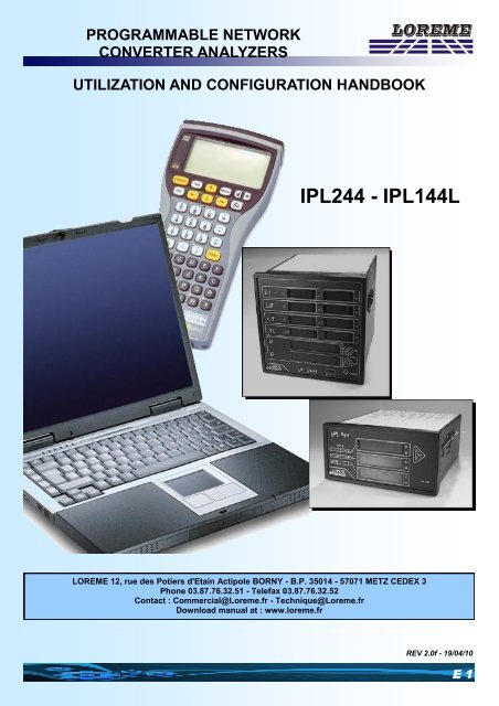
PROGRAMMABLE NETWORKCONVERTER ANALYZERSUTILIZATION AND CONFIGURATION HANDBOOKIPL244 - IPL<strong>144L</strong><strong>LOREME</strong> 12, rue des Potiers d'Etain Actipole BORNY - B.P. 35014 - 57071 METZ CEDEX 3Phone 03.87.76.32.51 - Telefax 03.87.76.32.52Contact : Commercial@Loreme.fr - Technique@Loreme.frDownload <strong>manual</strong> at : www.loreme.frREV 2.0f - 19/04/10E 1
Table of contentsDEVICE PRESENTATION .......................................................................... p3USERINTERFACE ............................................................................ p31) IPL244 ................................................................................ p32) IPL<strong>144L</strong> .............................................................................. p5DIALOGUE - TERMINALMODE .................................................................. p6PSION Workabout ........................................................................... p6PC with WINDOWS .......................................................................... p6VISUALIZATION ................................................................................ p7CONFIGURATION ............................................................................ p71) Method ............................................................................... p71.1) Menu selection ...................................................... p71.2) Parameter selection.............................................. p71.3) Value acquisition .................................................. p82) Language ............................................................................ p83) Caliber ................................................................................. p84) Network ............................................................................... p85) Energy ................................................................................. p86) Slots .................................................................................... p96.1) Analogical slot ...................................................... p96.2) Relay slot ............................................................... p96.2.1) Alarm ....................................................... p96.2.2) Energy meter .......................................... p106.2) RS 485 slot ............................................................ p107) Special functions ............................................................... p107.1) Single voltage mode ............................................. p107.2) Initial angle ............................................................ p10WIRING ........................................................................................................ p12RS485 COMMUNICATION MODBUS ......................................................... p161) Internal structure ........................................................................ p162) Communication .......................................................................... p163) Implementation ........................................................................... p174) Communication time .................................................................. p175) Frames structures ...................................................................... p196) Communication data .................................................................. p207) Data table .................................................................................... p21EMC CONSIDERATION ............................................................................. p271) Introduction ................................................................................. p272) Recommandation of use ............................................................ p272.1) General remarks ............................................................ p272.2) Power Supply ................................................................. p272.3) Inputs / Outputs ............................................................. p27E 2<strong>LOREME</strong> 12, rue des Potiers d'Etain - 57071 Metz 03.87.76.32.51 - Fax 03.87.76.32.52 - Email: Commercial@Loreme.fr - Technique@Loreme.fr
SOMMAIREDevice PresentationThe purpose of this configuration handbook is to allow to become familiar with the functions supplied by the device.The devices are provided of functions required to the analyst of every networks. It possess 3 voltage inputs and 3 currentinputs totaly isolated among it, who allows the realisation of direct and alternating measures, monophase or triphase,balanced or unbalanced, with or without neutral system.They can receive up to 8 slots. Number and functions are listed below and must be specified at the order:- analogical slot, current, voltage,- relay slot, alarm, energy meter,- communication slot, RS485 MODBUS / JBUS.Difference between twos devices comes from their display.1) IPL244:USER INTERFACEZONE ADisplaysZONE BIPL244 front side is composed of:- 10 displays with 8 mm red leds:- 8 values of 3 digits 1/2,- 2 valued of 7 digits 1/2.- 1 jack 3.5 plug for RS 232 link,- 3 keys:Push ButtonRS 232 link• "DSP" button allows to change size type displayed value onzone B, power, positive energy, negative energy.• "PH" button allows to change displayed phase on zone B,phase 1, 2, 3 or phases sum.• both buttons simultaneously pushed resets all energiesmeasures, if function is validate in configuration.Three displays modes are available. For A zone, change is made by RS232, and for B zone, by front side buttons.- Zone A, "Voltage/Current" display: - voltage and current for each phases,- network cos phi and frequency.Voltages and currents measures are in V and A when leds are off,KV and KA when leds "KV" and "KA" are on.Cos phi is capacitive, when "C" led is on, inductive, when "L" led ison. Frequency is given in Hz.Note: When device is connected to a unbalanced three-phase network with neutral, displayed voltages can be starvoltageor interlinked voltage.E 3
SOMMAIREVisualizationWhen switching on, device is automatically put in measure mode.On 2 lines display mode, the next messages will be displayed:CONFIGURATION Accessing to configuration modeTAPEZ SUR C Press on "C" keyAccess keyboard keys:"C" device configuration access."$" full-screen mode (PC only),"Enter" 2 lines display mode,The presentation of the measures in a full-screen mode is as follows:L1 L2 L3 3LVOLTAGE 230 V 229 V 225 V 228 VCURRENT 1.13 A 1.26 A 1.24 A 1.21 AFREQUENCY 50 Hz 50 Hz 50 Hz 50 HzCOS PHI 0.99 0.99 0.99 0.99ACTIVE P. 260 W 287 W 279 W 829 WREACTIVE P. 14 Var 15 Var 17 Var 46 VarAPPARENT P. 259 VA 287 VA 279 VA 829 VAACTIVE CONS. W. 54 kW.h 47 kW.h 49 kW.h 150 kW.hACTIVE GENE. W. 0 kW.h 0 kW.h 0 kW.h 0 kW.hREACTIVE IND. W. 0 kvar.h 0 kvar.h 0 kvar.h 0 kvar.hREACTIVE CAP. W. 5 kvar.h 4 kvar.h 4 kvar.h 13 kvar.hUNBALANCED TRIPHASE NETWORK WITH NEUTRALCT RATIO 1.00TI RATIO 1.00Full-screen mode is available only on a PC with KERMIT software. It isn't possible to use this mode with WIN-DOWS. Full-screen mode slows down the device. It is recommended to quit this mode when it is not necessary.CONFIGURATIONThe handbook explains in detail the different configurations possibilities:Language choice, input caliber, network, energy, slots.To enter configuration mode, just press "C" key.1) Method:At the configuration time, the user is asked different types of questions. For each one, several answers are possible.You will find below the detailed description of each case.1.1) Menu selecton:exemple: INPUT The user makes a choice by pressing the keys "Y" or "N".Y - N This choice allows to access the different menus of configuration.1.2) Parameter selection:exemple: VOLTAGE or VOLTAGE(Y - N) YES (Y - N) NOPrevious choice = YES: - pressing "Y" => choice validation = YES,- pressing "Enter" => choice validation = YES,- pressing "N" => choice changing = NO.Previous choice = NO:- pressing "N" => choice validation = NO,- pressing "Enter" => choice validation = NO,- pressing "Y" => choice changing = YES.E 7
SOMMAIREConfigurationChoice is made by pressing "Y" or "N" ke ys, and validation is made by pressing corresponding key to displayed answer("Y" for YES and "N" for NO) or "Enter" (PC)/"EXE" (PSION). Pressing key Enter/EXE without modification allowsto validate the previous answer.1.3) Value acquisition:exemple: LOW SCALE4 mATwo cases are possible:- validation without modification, just press Enter / EXE,- value modification on keyboard (simultaneous display), followed by validation with Enter / EXE.Note concerning acquisitionvalue :- It is possible, when a mistake is made during a value acquisition, before validating it, to go back by pressing "DEL" key(only on PSION), which re-displays the message without taking notice of the wrong value.- In configuration mode, if there is no action, device goes back in operating mode after a two minutes delay without takingnotice of modifications made before.- In configuration mode, if you want to shift to measure mode without taking notice of the modifications made before, youjust have to press "ESC" (PC) or "SHIFT + DEL" (PSION) key.During configuration, if sum has been chosen, device calculate:- channels mean for voltage, current and frequency.- channels sum for power and energy.- channels result for cos2) Language:Languages possibilities are:- French,- English.3) Caliber:On inputs voltage, 2 calibers are available in standard. To use one of twos, just select it in configuration:- voltage 125 V,- voltage 500 V.4) Network:Network wiring possibilities are:- in alternating current:- monophase,- balanced three-phase without neutral,- balanced three-phase with neutral,- unbalanced three-phase without neutral,- unbalanced three-phase with neutral.- in direct current:- 1 channel,- 2 channels,- 3 channels.It is also necessary to configure:- PT ratio (potential transformer),- CT ratio (current transformer).5) Energy:In this menu, it is possible to:- validate energies reset access by front side push-buttons.- reset all the energies.Warning: all energies are definitely reseted.E 8<strong>LOREME</strong> 12, rue des Potiers d'Etain - 57071 Metz 03.87.76.32.51 - Fax 03.87.76.32.52 - Email: Commercial@Loreme.fr - Technique@Loreme.fr
SOMMAIREConfiguration6) Slots:6.1) Analogical slot:Analogical slot configuration is composed of 2 rubrics:- output assignement:• measured value:- star voltage, interlinked voltage (only in 3 wattmeters),- current, invert current (only in 3 wattmeters),- frequency,- cos phi,- active, reactive, apparent power- consumed/generated active, inductive/capacitive reactive energy.• measured phase, according to network configuration:- phase 1,- phase 2,- phase 3,- phases sum or mean.• measure scale, low and high.- output parameter:• type, current or voltage,• scale, low and high,• numerical filter,• limitation.Numerical filter allows to smooth an analogical output, measure ofwhich would be disrupted, fluctuating or exposed to interferences.Limitation allows, for all measured signal values, to peak clip the outputsignal swing at scale configuration.6.2) Relay slot:Relay slot can be used in alarm or energy meter6.2.1) Alarm:Slot relay configuration in alarm is composed of 2 rubrics:- alarm assignement:• measured value:- star voltage, interlinked voltage (only in 3 wattmeters),- current, invert current (only in 3 wattmeters),- frequency,- cos ,- active, reactive, apparent power- consumed/generated active, inductive/capacitive reactive energy.• measured phase, according to the configuration of the network:- phase 1,- phase 2,- phase 3- phases sum or mean.- alarm parameters:• detection type, high or low threshold,• threshold value,• hysteresis.Detection type works in this way:- High threshold:.alarm is active when measure is beyond threshold,.alarm is inactive when measure is below threshold less hysteresis.- Low threshold:.alarm is active when measure is below threshold,.alarm is inactive when measure is beyond threshold more hysteresis.E 9
SOMMAIREConfiguration6.2.2) Energy meter:Relay slot configuration in energy meter is composed of 2 rubrics:- assigning the meter:• measured value:- consumed active energy,- generated active energy,- inductive reactive energy,- capacitive reactive energy,• phase measured according to network configuration:- phase 1,- phase 2,- phase 3,- sum of the phases.- counting parameters:• impulse load value, in kvar.h or kW.h.6.3) RS485 slot:Configuration of communication is composed of 3 rubrics:- device address in communication network, from 1 to 255,- speed, 600, 1200, 2400, 4800, 9600, 19200 or 38400 bauds,- parity, even, odd or without.Measured datas are available on differents formats:- 32 integer signed bits for measures,- 32 integer unsigned bits for energies,- 32 integer bits in per cent of full measure caliber for inverted current.For more details, see RS485 communication Modbus capter at the end of handbook.7) Special functions:Special functions are linked to network type used. Network configuration will allows differents access to functions.7.1) Single voltage mode:This function is used only for an unbalanced three-phase network with neutral. It allows to realise a unbalanced threephasewith neutral measure with a single voltage wired. This voltage, L2 phase, has to be wired on the 3 voltages inputs.7.2) Initial angle:Used only for a balanced three-phase network without neutral.This function allows a wiring adaptation. Phase angle acquisitionbetween voltage and current allows to use any voltage phases with any current phases.E 10<strong>LOREME</strong> 12, rue des Potiers d'Etain - 57071 Metz 03.87.76.32.51 - Fax 03.87.76.32.52 - Email: Commercial@Loreme.fr - Techni-
SOMMAIREConfigurationE 11
SOMMAIREDiagrams of connectionE 14<strong>LOREME</strong> 12, rue des Potiers d'Etain - 57071 Metz 03.87.76.32.51 - Fax 03.87.76.32.52 - Email: Commercial@Loreme.fr - Techni-
SOMMAIREDiagrams of connectionE 15
SOMMAIRERS485 Communication Modbus1) Internal structure:1.1) Presentation:The device is divided in two cells. Each cell has a specific functionwhile keeping a continuous exchange of pieces of information withthe second cell.The first cell is in charge of the measure, analysis and conversionfunction.The second cell is in charge of the communication function.The information exchange is continuous and automatic.1.2) Measure function:The measure cell runs the acquisition of the different signals and calculates all the values with regards to the configurationof the device.It also runs all the output functions (analogical, alarm, meter, RS 232). All measured or calculated parameters are storedin the system memory and are constantly refreshed.1.3) Communication function:The communication cell runs the RS485 communication interface in the MODBUS/JBUS protocol. It analyzes the requestsof the main station and answers if the device is addessed. It draws all these data from the system memory thatcan be continuously accessed.1.4) System memory:Each cell can continuously access the system memory. The latter has a dual access, which allows a reading/writing ofthe data whitout any possible internal conflicts.2) Communication:The type of protocol used is: MODBUS/JBUS in RTU mode. The communication has neither header nor delimitator offrame. The detection of the start of frame is made by a silence whose time is at least equal to the transmission of 3.5bytes. It implies that a frame received can be processed only after a time equal to the silence given before. The time ofthis silence is directly linked to the speed of transmission of the system:Ex: Speed 9600 bauds - no parity (10 bits/byte)Silence = (3.5 x 10) / 9600 = 3.64 msThe device starts to process the frame 3.64 ms after receiving the last byte.Note: The time separating two bytes from a same frame must be inferior to a silence. If the user does not comply withthis condition,the second byte will be considered as the first one of a new frame.The interval of time separating the end of reception of the last byte of the question frame and the end of emission of thefirst byte of the answer frame (detection of frame of the main station) constitutes the answer time of the device.This answer time Trep includes:- the silence (time of 3.5 bytes) Ts,- the processing of the frame Tt,- the emission of the first byte Te1.The time beyond which the device does not answer is called "TIME OUT". It depends on the transmission parameters(speed, format) and the type of the function asked (reading, writing). This time must be defined by the user and must besuperior to the answer time of the device.A complete communication cycle includes :- the question frame transmission Tq- the device answer time Trep- the answer frame transmission TrThree reasons might cause aTIME OUT:- wrong transmission data at the question frame time- wrong configuration of the TIME OUT on the main station- dependent station out-of-order.E 16<strong>LOREME</strong> 12, rue des Potiers d'Etain - 57071 Metz 03.87.76.32.51 - Fax 03.87.76.32.52 - Email: Commercial@Loreme.fr - Techni-
SOMMAIRERS485 Communication Modbus4.3) Energies reading:Reading of 8 words, 16 bytes, of the address $A01E to $A025 (active consumed and generated, and reactive inductiveand capacitive energies)- 8 bytes question frame Tq = (8 x 10) / 9600 = 8.33 ms- Silence Ts = (3.5 x 10) / 9600 = 3.64 ms- Processing Tt = 40 ms- Emission 1st byte Te1 = (1 x 10) / 9600 = 1.04 ms- Answer time Trep = Ts + Tt + Te1 = 44.68 ms- Answer frame (37 bytes) Tr = [(21 - 1) x 10] / 9600 = 20.83 ms- Complete cycle Tcyc = Tq + Trep + Tr = 73.84 msNote: The processing time Tt is fixed. It depends neither on the speed nor on transmission format. Consequently, fornew transmission parameters, all the times are going to change but for Tt. To set the TIME OUT of the system,you just have to calculate answer time Trep of the dependent station according to the parameters ofcommunication. For a total phase reading, the system time cycle is about 75 ms.4.4) Energies reset:Reset of the active consumed and generated, and reactive inductive and capacitive energies by the writing of word$55AA at the address $7000.- question frame Tq = (8 x 10) / 9600 = 8.33 ms- silence Ts = (3.5 x 10) / 9600 = 3.64 ms- processing Tt = 40 ms- emission 1st byte Te1 = (1 x 10) / 9600 = 1.04 ms- answer time Trep = Ts + Tt + Te1= 44.68 ms- answer frame 8 bytes Tr = [(8 - 1) x 10] / 9600 = 7.29 ms- complete cycle Tcyc = Tq + Trep + Tr = 60.3The processing time Tt is fixed. It depends neither on the speed nor on the transmission format. Consequently, for newtransmission parameters, all the times are going to change but for Tt. To set the TIME OUT of the system, you just haveto calculate the answer time Trep of the dependent station according to the parameters of communication.For a completereset of the energies, the time of cycle of the system is about 60 ms.4.5) Energy value writting:Writing of one energy value at once, active consumed or generated, reactive inductive or capacitive energy on the sumof the channels. Writting of 2 words, 4 bytes, of the adress $A01E $A01F (active consummed energy).E 18<strong>LOREME</strong> 12, rue des Potiers d'Etain - 57071 Metz 03.87.76.32.51 - Fax 03.87.76.32.52 - Email: Commercial@Loreme.fr - Techni-
SOMMAIRERS485 Communication Modbus- Question frame Tq = (13 x 10) / 9600 = 13.54 ms- Silence Ts = (3.5 x 10) / 9600 = 3.64 ms- Processing Tt = 40 ms- Emission 1st byte Te1 = (1 x 10) / 9600 = 1.04 ms- Answer time Trep = Ts + Tt + Te1 = 44.68 ms- Answer frame Tr = [(8 - 1) x 10] / 9600 = 7.29 ms- Complete cycle Tcyc = Tq + Trep + Tr = 65.51 msNote: The processing time Tt is fixed. It depends neither on the speed nor on the format of transmission. Consequently,for new parameters of transmission, all the times are going to change but for Tt. To set the TIME OUT of thesystem, you just have to calculate the answer time Trep of the dependent station according to the parameters ofommunication. For a writing of energy value, the time of cycle of the system is about 65 ms.5) Frames structure:5.1) Words reading:Function code used: $03 or $04Table reading:address $A000 to $A05BQuestion: l<strong>eng</strong>th of frame 8 bytes.Answer: l<strong>eng</strong>th of frame 5 bytes+ number of read bytes.5.2) Word writing:Function code used: $06Reset of all energies: Address $7000 Word value $55AAQuestion: l<strong>eng</strong>th of frame 8 bytesAnswer: l<strong>eng</strong>th of frame 8 bytes5.3) Words writting:Function code used: $10Writing of an energy value:Active consumed energy:address $A01EActive generated energy: address $A020Reactive inductive energy: address $A022Reactive capacitive energy: address $A024Question: l<strong>eng</strong>th of frame 9 bytes + number of written bytes.E 19
SOMMAIRERS485 Communication ModbusAnswer: l<strong>eng</strong>th of frame 8 bytes.5.4) Exception frame:When a physical error of transmission of a question frame occurs (CRC16 or parity), the dependent station does notanswer.If an error of frame (data address, function, value) occurs, an answer of exception will be emitted by the dependent station.L<strong>eng</strong>th of frame: 5 bytes.Features of the exception frame:- Function code:The function code of the exception frame is identical to the one of the question frame, but its bit of strong load is set to 1(logical or with $80).- Error code:Error code establishes the reason of a sending of an exception frame.Error frameMeaning$01 Function code not used.Only the functions reading of words, $03 or $04,writing of a word $06, or words $10 are allowed.$02 Non-valid data address.Memory access not allowed.$03 Non-valid value.Value of word not allowed.6) Communication data:6.1) Reading:All measures are accessible in reading mode, voltage, current, frequency, active, reactive, apparent power, cosinus phi,consumed/generated active and inductive/capacitive reactive energy on phases 1, 2, 3 and sum.Numerical values are:- on 2 words at signed 32 bits integer format (4 bytes), for voltages,currents, frequencies, active, reactive, apparent powers and cos .- on 2 words at 32 bits integer format (4 bytes) in % of full caliber ofmeasure for inverse current.- on 2 words unsigned 32 bits integer format (4 bytes), for energies(value in kW.h or kVAR.h).Consult the enclosed tables for measures detail.6.2) Writing:It's possible to reset all energies by a write. Reset is made by writtiing $55AA value at $7000 address.Phases sum energy values are accessible individually in writtig and only one value at time. Write format is the same asreading one, unsigned 32 bits integer format.E 20<strong>LOREME</strong> 12, rue des Potiers d'Etain - 57071 Metz 03.87.76.32.51 - Fax 03.87.76.32.52 - Email: Commercial@Loreme.fr - Techni-
SOMMAIRERS485 Communication Modbus6.3) Data format:Datas are given in integer 32 bits format.Datas transmitted lest significant word first, compound of 4 bytes i.e 2 words.The datum of reset is a hexadecimal code. This code is compound of 2 bytes, i.e.1 word. Code $55AA: reset of all energies.7) Data Table:Decimal word adrdess(Hexadecimal)b7 b6 b5 b4 b3 b2 b1 b0 TotalWords40960 ($A000) Invert current Byte 1 Word 1 1 1(% of the full caliber) Byte 2 240961 ($A001) (A) Byte 3 Word 2 2 3Byte 4 440962 ($A002) Star voltage Byte 1 Word 1 3 5phase 1 Byte 2 640963 ($A003) (V) Byte 3 Word 2 4 7Byte 4 840964 ($A004) Star voltage Byte 1 Word 1 5 9phase 2 Byte 2 1040965 ($A0005) (V) Byte 3 Word 2 6 11Byte 4 1240966 ($A006) Star voltage Byte 1 Word 1 7 13phase 3 Byte 2 1440967 ($A007) (V) Byte 3 Word 2 8 15Byte 4 1640968 ($A008) Interlinked voltage Byte 1 Word 1 9 17Phase 1-2 Byte 2 1840969 ($A009) (V) Byte 3 Word 2 10 19Byte 4 2040970 ($A00A) Interlinked voltage Byte 1 Word 1 11 21Phase 2-3 Byte 2 2240971 ($A00B) (V) Byte 3 Word 2 12 23Byte 4 2440972 ($A00C) Interlinked voltage Byte 1 Word 1 13 25Phase 3-1 Byte 2 2640973 ($A00D) (V) Byte 3 Word 2 14 27Byte 4 28BytesE 21
SOMMAIRERS485 Communication ModbusData table suiteDecimal word adrdess(Hexadecimal)b7 b6 b5 b4 b3 b2 b1 b0 TotalWords40974 ($A00E) Current Byte 1 Word 1 15 29Phase 1 Byte 2 3040975 ($A00F) (A) Byte 3 Word 2 16 31Byte 4 3240976 ($A010) Current Byte 1 Word 1 17 33Phase 2 Byte 2 3440977 ($A011) (A) Byte 3 Word 2 18 35Byte 4 3640978 ($A012) Current Byte 1 Word 1 19 37Phase 3 Byte 2 3840979 ($A013) (A) Byte 3 Word 2 20 39Byte 4 4040980 ($A014) Active power Byte 1 Word 1 21 41Network Byte 2 4240981 ($A015) (W) Byte 3 Word 2 22 43Byte 4 4440982 ($A016) Reactive power Byte 1 Word 1 23 45Network Byte 2 4640983 ($A017) (VAR) Byte 3 Word 2 24 47Byte 4 4840984 ($A018) Apparente power Byte 1 Word 1 25 49Network Byte 2 5040985 ($A019) (VA) Byte 3 Word 2 26 51Byte 4 5240986 ($A01A) Network Cosinus Byte 1 Word 1 27 53(value x 100) Byte 2 5440987 ($A01B) Byte 3 Word 2 28 55Byte 4 5640988 ($A01C) Network Frequency Byte 1 Word 1 29 57(value Hz x 100) Byte 2 5840989 ($A01D) Byte 3 Word 2 30 59Byte 4 6040990 ($A01E) Network active Byte 1 Word 1 31 61Consumed energy Byte 2 6240991 ($A01F) (KW.h) Byte 3 Word 2 32 63Byte 4 64BytesE 22<strong>LOREME</strong> 12, rue des Potiers d'Etain - 57071 Metz 03.87.76.32.51 - Fax 03.87.76.32.52 - Email: Commercial@Loreme.fr - Techni-
SOMMAIRERS485 Communication ModbusData table suiteDecimal word adrdess(Hexadecimal)b7 b6 b5 b4 b3 b2 b1 b0 TotalWords40992 ($A020) Network reactive Byte 1 Word 1 33 65Inductive energy Byte 2 6640993 ($A021) (KVAR.h) Byte 3 Word 2 34 67Byte 4 6840994 ($A022) Network active Byte 1 Word 1 35 69Generated energy Byte 2 7040995 ($A023) (KW.h) Byte 3 Word 2 36 71Byte 4 7240996 ($A024) Network reactive Byte 1 Word 1 37 73Capacitive energy Byte 2 7440997 ($A025) (KVAR.h) Byte 3 Word 2 38 75Byte 4 7640998 ($A026) Active power Byte 1 Word 1 39 77Phase 1 Byte 2 7840999 ($A027) (W) Byte 3 Word 2 40 79Byte 4 8041000 ($A028) Active power Byte 1 Word 1 41 81Phase 2 Byte 2 8241001 ($A029) (W) Byte 3 Word 2 42 83Byte 4 8441002 ($A02A) Active power Byte 1 Word 1 43 85Phase 3 Byte 2 8641003 ($A02B) (W) Byte 3 Word 2 44 87Byte 4 8841004 ($A02C) Reactive power Byte 1 Word 1 45 89Phase 1 Byte 2 9041005 ($A02D) (VAR) Byte 3 Word 2 46 91Byte 4 9241006 ($A02E) Reactive power Byte 1 Word 1 47 93Phase 2 Byte 2 9441007 ($A02F) (VAR) Byte 3 Word 2 48 95Byte 4 9641008 ($A030) Reactive power Byte 1 Word 1 49 97Phase 3 Byte 2 9841009 ($A031) (VAR) Byte 3 Word 2 50 99Byte 4 100BytesE 23
SOMMAIRERS485 Communication ModbusData table suiteDecimal word adrdess(Hexadecimal)b7 b6 b5 b4 b3 b2 b1 b0 TotalWords41010 ($A032) Apparent power Byte 1 Word 1 51 101Phase 1 Byte 2 10241011 ($A033) (VA) Byte 3 Word 2 52 103Byte 4 10441012 ($A034) Apparent power Byte 1 Word 1 53 105Phase 2 Byte 2 10641013 ($A035) (VA) Byte 3 Word 2 54 107Byte 4 10841014 ($A036) Apparente power Byte 1 Word 1 55 109Phase 3 Byte 2 11041015 ($A037) (VA) Byte 3 Word 2 56 111Byte 4 11241016 ($A038) Cosinus phi Byte 1 Word 1 57 113Phase 1 Byte 2 11441017 ($A039) (Value x 100) Byte 3 Word 2 58 115Byte 4 11641018 ($A03A) Cosinus phi Byte 1 Word 1 59 117Phase 2 Byte 2 11841019 ($A03B) (Value x 100) Byte 3 Word 2 60 119Byte 4 12041020 ($A03C) Cosinus phi Byte 1 Word 1 61 121Phase 3 Byte 2 12241021 ($A03D) (Value x 100) Byte 3 Word 2 62 123Byte 4 12441022 ($A03E) Frequency Byte 1 Word 1 63 125Phase 1 Byte 2 12641023 ($A03F) (value Hz x 100) Byte 3 Word 2 64 127Byte 4 12841024 ($A040) Frequency Byte 1 Word 1 65 129Phase 2 Byte 2 13041025 ($A041) (value Hz x 100) Byte 3 Word 2 66 131Byte 4 13241026 ($A042) Frequency Byte 1 Word 1 67 133Phase 3 Byte 2 13441027 ($A043) (value Hz x 100) Byte 3 Word 2 68 135Byte 4 136BytesE 24<strong>LOREME</strong> 12, rue des Potiers d'Etain - 57071 Metz 03.87.76.32.51 - Fax 03.87.76.32.52 - Email: Commercial@Loreme.fr - Techni-
SOMMAIRERS485 Communication ModbusData table suiteDecimal word adrdess(Hexadecimal)b7 b6 b5 b4 b3 b2 b1 b0 TotalWords41028 ($A044) Active consumed energy Byte 1 Word 1 69 137Phase 1 Byte 2 13841029 ($A045) (KW.h) Byte 3 Word 2 70 139Byte 4 14041030 ($A046) Reactive inductive energy Byte 1 Word 1 71 141Phase 1 Byte 2 14241031 ($A047) (KVAR.h) Byte 3 Word 2 72 143Byte 4 14441032 ($A048) Active generated energy Byte 1 Word 1 73 145Phase 1 Byte 2 14641033 ($A049) (KW.h) Byte 3 Word 2 74 147Byte 4 14841034 ($A04A) Reactive capacitive energy Byte 1 Word 1 75 149Phase 1 Byte 2 15041035 ($A04B) (KVAR.h) Byte 3 Word 2 76 151Byte 4 15241036 ($A04C) Active consumed energy Byte 1 Word 1 77 153Phase 2 Byte 2 15441037 ($A04D) (KW.h) Byte 3 Word 2 78 155Byte 4 15641038 ($A04E) Reactive inductive energy Byte 1 Word 1 79 157Phase 2 Byte 2 15841039 ($A04F) (KVAR.h) Byte 3 Word 2 80 159Byte 4 16041040 ($A050) Active generated energy Byte 1 Word 1 81 161Phase 2 Byte 2 16241041 ($A051) (KW.h) Byte 3 Word 2 82 163Byte 4 16441042 ($A052) Reactive capacitive energy Byte 1 Word 1 83 165Phase 2 Byte 2 16641043 ($A053) (KVAR.h) Byte 3 Word 2 84 167Byte 4 16841044 ($A054) Active consumed energy Byte 1 Word 1 85 169Phase 3 Byte 2 17041045 ($A055) (KW.h) Byte 3 Word 2 86 171Byte 4 172BytesE 25
SOMMAIRERS485 Communication ModbusData table suiteDecimal word adrdess(Hexadecimal)b7 b6 b5 b4 b3 b2 b1 b0 TotalWordsBytes41046 ($A056) Reactive inductive energy Byte 1 Word 1 87 173Phase 3 Byte 2 17441047 ($A057) (KVAR.h) Byte 3 Word 2 88 175Byte 4 17641048 ($A058) Active generated energy Byte 1 Word 1 89 177Phase 3 Byte 2 17841049 ($A059) (KW.h) Byte 3 Word 2 90 179Byte 4 18041050 ($A05A) Reactive capacitive energy Byte 1 Word 1 91 181Phase 3 Byte 2 18241051 ($A05B) (KVAR.h) Byte 3 Word 2 92 183Byte 4 184E 26<strong>LOREME</strong> 12, rue des Potiers d'Etain - 57071 Metz 03.87.76.32.51 - Fax 03.87.76.32.52 - Email: Commercial@Loreme.fr - Techni-
SOMMAIREEMC Consideration1) Introduction:In order to satisfy its policy as regards EMC, based on the Community directive 89/336/CE, the <strong>LOREME</strong>company takes into account the standards relative to this directive from the very start of the conception ofeach product.As the devices are devised to work in industrial environments, the various tests are carried out in the sight ofthe EN 50081-2 and EN 50082-2 standards, in order to make out a statement of conformity.As the devices lie in certain typical configurations during the tests, it is not possible to secure the outcomes inany possible configuration. To ensure the best functionning of each device, it would be judicious to complywith several recommendations of use.2) Recommendations of use:2.1 ) General remarks:- Comply with the recommendations of assembly indicated in the technical sheet (direction of assembly, spacingbetween the devices, ...).- Comply with the recommendations of use indicated in the technical sheet (temperature range, protectionindex).- Avoid dust and excessive humidity, corrosive gas, considerable sources of heat.- Avoid disturbed environments and disruptive phenomena or elements.- If possible, group together the instrumentation devices in a zone separated from the power and relay circuits.- Avoid the direct proximity with considerable power distance switches, contactors, relays, thyristor powergroups, ...- Do not get closer within fifty centimetres of a device with a transmitter (walkie-talkie) of a power of 5 W, becausethe latter can create a field with an intensity higher than 10 V/M for a distance fewer than 50 cm.2.2 ) Power supply:- Comply with the features indicated in the technical sheet (power supply voltage, frequency, allowance of thevalues, stability, variations ...).- It is better that the power supply should come from a system with section switches equipped with fuses forthe instrumentation element and that the power supply line be the most direct possible from the sectionswitch.- Avoid using this power supply for the control of relays, of contactors, of electrogates, ...- If the switching of thyristor statical groups, of <strong>eng</strong>ines, of speed variator, ... causes strong interferences onthe power supply circuit, it would be necessary to put an insulation transformer especially intended for instrumentationlinking the screen to earth.- It is also important that the installation should have a good earth system and it is better that the voltage inrelation to the neutral should not exceed 1V, and the resistance be inferior to 6 ohms.- If the installation is near high frequency generators or installations of arc welding, it is better to put suitablesection filters.2.3 ) Inputs / Outputs:- In harsh conditions, it is advisable to use sheathed and twisted cables whose ground braid will be linked tothe earth at a single point.- It is advisable to separate the input / output lines from the power supply lines in order to avoid the couplingphenomena.- It is also advisable to limit the l<strong>eng</strong>ths of data cables as much as possible.E 27