manual CNL45 - LOREME
manual CNL45 - LOREME
manual CNL45 - LOREME
- No tags were found...
Create successful ePaper yourself
Turn your PDF publications into a flip-book with our unique Google optimized e-Paper software.
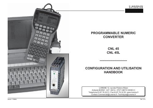
PROGRAMMABLE NUMERICCONVERTERCNL 45CNL 45L-------------------------CONFIGURATION AND UTILISATIONHANDBOOK<strong>LOREME</strong> 12, rue des Potiers d'EtainActipole BORNY - B.P. 35014 - 57071 METZ CEDEX 3Telephone 03.87.76.32.51 - Fax 03.87.76.32.52 - www.loreme.frContact: Commercial@Loreme.fr - Technique@Loreme.frIssued: 17/08/04Rev 4.1a
TABLE OF CONTENTSDIALOGUE - TERMINAL MODE ................................................................1) PSION serie 2 ...............................................................................2) PSION Workabout .......................................................................3) PC with DOS ................................................................................4) PC with WINDOWS 3.11 ..............................................................5) PC with WINDOWS 95/98 ............................................................6) Visualization ................................................................................DEVICE PRESENTATION ..........................................................................CONFIGURATION ......................................................................................1) Method .........................................................................................1.1) Menu selection ...............................................................1.2) Parameter selection .......................................................1.3) Value acquisition ............................................................2) Langage .......................................................................................3) Input .............................................................................................4) Analog output ..............................................................................5) Special functions ........................................................................MEASURE MODIFICATION .......................................................................EMC CONSIDERATION .............................................................................1) Introduction .................................................................................2) Installation and utilization rules .................................................2.1) General remarks .............................................................2.2) Power supply ..................................................................2.3) Inputs / Outputs .............................................................INPUTS - OUTPUTS WIRING .....................................................................TERMINAL - DEVICE LINK..........................................................................page 1page 1page 1page 2page 2page 2page 3page 3page 3page 3page 3page 3page 3page 4page 4page 4page 4page 5page 5page 5page 5page 5page 5page 5page 6page 6DIALOGUE - TERMINAL MODENumeric devices can converse with all terminal emulation mode systems. Asthe dialogue and configuration part are in device's memory, no software orspecific interface are necessary for their configuration.Two terminal emulation mode systems are presented: the PSION and the PC.Differents procedures are enumerated below.1) PSION serie 2:First of all manipulation, plug in "COMMS LINK" on the PSION. To start up thePSION, push on the "ON" key.The PSION displays this menu:RECH SAUV AGENDACALC PROG EFFACEPush on the "C" key until the menu "COMMS", and validate with "EXE".The PSION displays this menu: TRANSMIT RECEIVESETUP TERM AUTOPush on the "T" key until the menu "TERM", and validate with "EXE" to obtaina empty screen. The PSION is now in terminal mode and you can link thePSION to the device, by plugging in the RS 232. The measure is displayed, toconfigurate, push on the "C" key.2) PSION Workabout:To start up the PSION push on the "ON" key.At the presentation, push on the "MENU" key. Select "SYSTEME SCREEN"mode and validate by "ENTER".Icons display: DATA CALC SHEET PROGRAM COMMSSelect icon "COMMS" and validate by "ENTER", on display, a cursor flashing.The PSION is in terminal mode. Plug in "RS232" on PC. The measure isdisplayed and, to configure, push "C" on keyboard.To quit terminal mode and switch off PSION, push on "OFF" key. When you restartthe PSION in terminal mode, it start automaticaly and directely in terminalmode without re-start configuration.1
3) PC with DOS:The terminal emulation mode software with DOS "IBM®-PC KERMIT-MSV2.26" is available at simple request. After the PC has booted, type "a: K" thenpress "ENTER". The PC is in terminal mode and uses COM port 1.If you want to use the second serial communication port (COM2), type:"A:KERMIT" and "ENTER" to launch the program,"SET PORT 2" and "ENTER" to select COM2,"SET BAUD 9600" and "ENTER" to select speed,"CONNECT" and "ENTER", to enter in the terminal mode.The PC is now emulating a terminal and may be connected to the device byplugging in the RS 232 link cable.Measure is now displayed and configuration's acces allowed by a press on "C"key.To quit kermit, press "CTRL-$" then press the key "C".When the message KERMIT-MS appears, type "QUIT" to return to MS-DOScommands.5) PC with WINDOWS 95/98:To start up terminal program:1 - Clique on button "START",2 - Tick off "PROGRAMS", "ACCESSOIRES", and "HYPER TERMINAL",3 - Click twice onThe following window is displayed. Enter aname for a new connection and validate, thehereunder window will appearChoose a communication port and validate.The belowing windows is displayed4) PC with WINDOWS 3.11:Start WINDOWS and in "ACCESSOIRES" group, double-click onicon wich get access to terminal mode.In "PARAMETRES" menubar, click on"COMMUNICATION" sub-menu. We accessto the following windows. Configurecommunication parameters, 9600 bauds, noparity, 8 data bits, 1 stop bit, no flow controland validate.Begin terminal emulation by click on"PARAMETRES", then on "EMULATIONTERMINAL". the following board isdisplayed.Choose terminal mode DEC-VT-100(ANSI) andvalidate. The PC is in terminal mode, connect itto device by plugging the RS232 link cable.Measure is now displayed and to access atconfiguration, press on "C" key.Configure communication parameters, 9600bauds, no parity, 8 data bits, 1 stop bit, no flowcontrol and validate. The PC is in terminalmode, connect to device by plugging in theRS232 link cable. Measure is now displayedand to access at the configuration, press on"C" key .When quitting HyperTerminal will be diplayed thefollowing window. To dialog with all <strong>LOREME</strong>devices without re-start all the method, click on"OK"To load <strong>LOREME</strong> session directly:1 - Click on button "Start".2 - Tick off "Programs", "Accessories", and "HyperTerminal".3 - Click twice on the icon2
6) Visualization:When it starts up, the device is in measure mode.Two datas are send to terminal:10 mV Value of the input measure,11.99 mA Value of the output result.To access configuration, type on "C" key and follow the configurationprocedure.DEVICE PRESENTATIONThe purpose of this handbook is to allowyou to become familiar with the differentsfunctions of the device.It's a converter in 2 wires technical,supplied by the current loop. Only 2wires has needed for power supply andanalog output.Its input capacity are as follows:mV, V, mA, resistance (2 or 3 wires),Pt100 (2 or 3 wires), Tc (B, E, J, K, R; S,T) and potentiometer.CONFIGURATIONThis <strong>manual</strong> recapitulates a detailed account of several configuration possibilities:Language, input, analog output, special functions.To access configuration mode, type on "C" key.1) Method:At configuration, several question types are asked. For each of them, severalanswers are possibles. Description of each of them:1.1) Menu selection:Example: INPUTY - Nled indicating voltagepresenceJack 3.5 for a seriallink allowing the deviceconfiguration.The choice is done by typing on "Y" or "N" keys.This choice allows access to different configuration menus.1.2) Parameter selection:Example: VOLTAGE (mV) or VOLTAGE (mV)(Y-N) YES(Y-N) NOPrevious choice = YES:Previous choice = NO:- push on "Y" => Validation of choice = YES,- push on " " => Validation of choice = YES,- push on "N" => Change of choice = NO.- push on "N" => Validation of choice = NO,- push on " " => Validation of choice = NO,- push on "Y" => Change of choice = YES.Choices are made pushing on "Y" or "N" keys, and validation by pushing on" " (PC) / "EXE" (PSION) when the answer "Y" or "N" is displayed.Pushing on the key " " / "EXE" without modification allows validateprevious answer.1.3) Value acquisition:Example: LOW SCALE4 mATwo possibilities:- The validation without modification by pushing on " " / "EXE",- The keyboard value modification (simultaneous display), then the validationby " " / "EXE".Note concerning the value acquisition:- It is possible, when a mistake is made during a value acquisition, beforevalidating it, to go back pressing "DEL" key (only on PSION), which redisplaysthe message without taking notice of the wrong value.- In configuration mode, if you want to shift to measure mode without takingnotice of the modifications made before, you just have to press "ESC" (PC)or "SHIFT + DEL" (PSION) key.3
2) Language:The language possibilities are:- english,- french.3) Input:The input possibilities are:- Voltage (mV, V),- Current (mA),- Resistance (Ohms),- Pt 100 (°C),- Thermocouple (°C),for each type of input, you can choose:- the low scale,- the high scale.Particularity:- Thermocouple:Choice of thermocouple type (B, E, J, K, R, S, T),Choice of compensation type (internal or external).Choose the internal compensation when the thermocouple isconnected on device with a compensation cable.Choose the external compensation when a compensation boxwhere the temperature will be know and fixed is used. Enter thistemperature as the external compensation value.- Potentiometer:Configure voltage input (mV):- start of scale: 0 mV,- end of scale: 140 mV.Move the potentiometer at the start and at the end of the range andmeasure the values.Change the voltage input (mV):- start of scale: Start range value,- end of scale: End range value.View wiring diagram for potentiometer cabling.4) Analog output:As the device is in 2 wires technical, the analog output is intented in this typeand this scale: current output 4-20 mA.Adjustables parameters are:- security value,- response time,- limitation.The security value allows to set the output on a known state whenthere is a sensor breaking or a measure range overflow.The acquisition value is sended to the output.The limitation allows, for all input signal values, to peak clip the outputsignal swing at scale configuration.Only security value goes beyond this function.The response time is adjustable from 200 ms to 60 s.5) Special functions:This functions are not available for Pt100 or TC inputs:Square root: this function executes a square root on the measure percentageof the input range and is reported on analog output.Special linearization: when this function is choosed, it is directly validated,but the linearization configuration isn't modified. To modify the speciallinearization, it is necessary to validate by YES the configuration suggest.When the special linearization is enabled, the converter will use the curve thatyou program (2).To have a special linearization curve(2), it's necessary to put for each curvepoint the physical input value and thecorresponding physical output value(max.: 26 signed points including 0 %and 100 % of the input). So, for eachmeasure in the input range (devicecan't use the linearization functionout of range), the device will make thecorresponding of linearized outputvalue.OUTPUTCorresponding valuesmV, mA, Ohms(1) Converter responsecurve(2) Special linearisationresponse curveINPUTMeasurement valuemV, mA, Ohms4
MEASURE MODIFICATIONSometimes, it may be interesting to modify measure by a keyboard intervention.It can be used in many situations:- Sensor's degradation,- to calibrate the input with magnifying effect to obtain a betteraccuracy in the measure window.To shift the measure, it is necessary:- to be in measure mode,- type on "+" or "-" to access at the function,- the display on terminal become:100.2 DEG measure value corrected,OFFSET 2 offset value.- use keys "+" and "-" to adjust offset, measure is directly modify.- type on "ENTER" to memorize offset.Remarks:When the device is not supplyed or in configuration, offset remains active.To reset offset, recall the shift function, put back offset at zero and validate itby "ENTER".EMC CONSIDERATION1) IntroductionIn order to insure its policy concerning EMC, based on the European directive89/336/CE, <strong>LOREME</strong> takes into account all the standards relative to thisdirective as soon as the design of each device starts.All the tests made on our devices, designed to work in industrial plants, havebeen made regarding the EN 50081-2 and EN 50082-2 standards in order toedit a conformity certificate.It is difficult to guarantee all the results concerning EMC because tests aremade in a standard and typical configuration. Results may vary when achange of configuration occurs.In order to be sure to use all the capabilities of the device, it will be necessaryto respect a few rules concerning its installation.2) Installation and utilization rules2.1) General remarks- Installation should be made with respect to the informations given intechnical documents (installation, spacing between each device ...).- Utilization conditions should be in accordance (temperature range, protectionlevel) specified in technical datasheet.Avoide dust, excessive humidity, corrosives atmospheres or important heatsources.- Noisy environment or elements creating perturbations should be avoided.If it is possible, it will be better to install instrumentation devices separatelyfrom hi-power or commutation devices.Do not install measurement devices close to hi-power relays, thyristorgroups, contactors or all electromagnetic noise generators...Do not use a portable transmitter (walkie-talkie) at less than 50 cm of thedevice , whith a power of 5 W transmitter may generate a field which intensitymay be more than 10 V/m at a distance near of 50 cm.2.2) Power supply- Respect to the technical specifications given in the device's datasheet(supply voltage, frequency, tolerance of values, stability, variations ...).- The power supply of the device should be issued from a supply systemusing section switches and fuses made for instrumentation devices, and thesupply line should be as direct as possible from section switch.Don't use this power supply for relays, contactors or valves command.- An isolating transformer, with its screen shorted to ground may benecessary if the supply circuit is made noisy with commutation of thyristors,relays, motors, speed variators ...- It's important that the installation has to be connected to ground.The voltage between neutral and earth must be less than 1 V and theresistance must be less than 6 Ohms.- If the equipment has been installed near hi-frequency generators or arcwelding installations, it may be useful to install adequat filters on the mainssupply.2.3 ) Inputs / Outputs- In a noisy environment, it will be better to use shielded and twisted wires.The ground connection will be made at a single end of the wire.- I / O lines should be well separated from supply wires in order to avoidcoupling between these wires.- Data wires length should be as short as possible.5
WIRING INPUTS - OUTPUTSPC - TRANSMITTER LINKmV input: terminal D (+), terminal E (-)V input: terminal B (+), terminal E (-)mA input:terminal D (+), terminal E (-), external shunt of 2.5 OhmsResistance input (2 wires): terminal D (+) and F (+), terminal EResistance input (3 wires): terminal D (+), terminal F (line), terminal E (-),Pt 100 input (2 wires): terminal D (+) and F (+), terminal EPt 100 input (3 wires): terminal D (+),terminal F (line), terminal E (-),Tc input: terminal D (+), terminal E (-)Potentiometer input: terminal A (+Ref), terminal D (+), terminal E (-)Supply / analog output: terminal K (+), terminal L (-)Terminal test: terminal G (+), terminal H (-)6


