RS-M920 Manual
RS-M920 Manual
RS-M920 Manual
- No tags were found...

You also want an ePaper? Increase the reach of your titles
YUMPU automatically turns print PDFs into web optimized ePapers that Google loves.
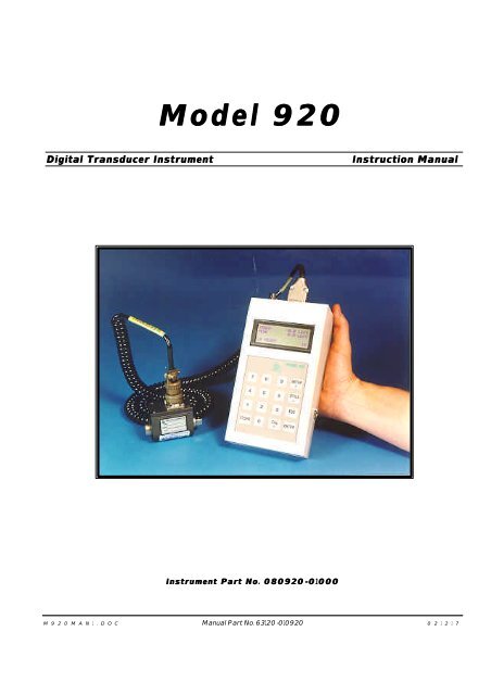
Model 920Digital Transducer InstrumentInstruction <strong>Manual</strong>Instrument Part No. 080920-0100001000M 9 2 0 M A N 1 . D O C <strong>Manual</strong> Part No. 63120-010920 0 2 1 2 1 7
MODEL 920TABLE OF CONTENTS1.0 PRELIMINARIES............................31.1 PRECAUTIONS ..................................................31.1.1 Site Considerations............................. 31.1.2 Handling..................................................... 31.1.3 Cleaning ..................................................... 31.1.4 On Re-packing........................................ 31.1.5 Before You Begin .................................. 31.2 INTRODUCTION ................................................41.2.1 How to Use This <strong>Manual</strong> ..................41.2.2 Model 920 Operation Overview ..41.2.3 Transducer Selection .........................41.2.4Test Setup ................................................41.2.5 Data Recording .....................................51.2.6Viewing Data ..........................................51.2.7 Data Storage & Upload....................51.3 CONNECTIONS...................................................51.3.1 Printer/Computer Upload ................51.3.2 Pinouts .......................................................52.0 PREPARATION ..............................62.1 THE MAIN SCREEN........................................ 62.2 CAL SCREEN OVERVIEW ............................ 62.3 SETUP SCREEN OVERVIEW...................... 62.4 STORE SCREEN OVERVIEW...................... 62.5 UTILITIES SCREEN OVERVIEW ................ 63.0 INSTRUMENT SETUP ....................73.1 STARTING UP THE 920..............................73.2 TRANSDUCER SETUP....................................73.2.1 Set Up <strong>RS</strong> TechnologiesTransducer............................................... 73.2.2 Set Up Custom Transducer ......83.3 TEST SETUP ..................................................... 83.4 CHANGING FREQUENCY RESPONSE ..... 94.0 OPERATION .................................104.1 TAKING DATA..................................................104.2 REVIEWING DATA & STATISTICS..........104.3 PRINTING DATA AND STATISTICS........... 114.4 SENDING DATA TO A COMPUTER............ 114.5 ERASING DATA............................................... 124.6 SETTING DATA & TIME.............................. 124.7 SETTING BAUD RATE.................................. 125.0 OTHER INFORMATION..................135.1 SPECIFICATIONS.............................................135.2 TESTING HAND TORQUE WRENCHES..135.2.1Equipment Required ........................... 135.2.2 Setting Up The Model 920 ...... 135.2.3 Testing Hand Wrenches ............14M 9 2 0 M A N 1 . D O C 2 09/03/03
MODEL 920NOTEThe Start and End Time values work togetherto end the recording cycle. Whenthe transducer input drops below thevalue set in the Start field for the length oftime set in End Time field, the recordingis completed.5. Measure In the Measure PEAK field, TQ press the CLICK ENTER TQ key to toggle the display "Enter" between . PEAK TQ and CLICK "Click" TQ. To , record the “click” CLICK TQ point of. the hand wrench, select Max CLICK TQ; to record just the peak or maximum Down applied torque, . select PEAK TQ. Press the down arrowkey to advance to the next setup field.NoteIf you will be using the Model 920 tocheck “click-type” hand torque wrenches,you may want to set the START field toabout 60% of the target value. For example,if checking a wrench set at 100 in-lbs,set the START value to around 60 in-lbs.6. Low In the Low (units) field enter low the limit low limit of. acceptable torque Down or force and . press the Calculating down arrow Statistic key. This . value is used for calculatingstatistics.7. High high limit .7. Down In the High (units) . field enter the high Calculating limitstatistic of acceptable . torque or force and press thedown arrow key. This value is also used for8. calculating statistics. Enter . ESC 8. . Press the ENTER key to save your changesand then press the ESC key to return to thesetup screen.9. 9. CW Press CCW the 2 key to toggle "Setup between Menu" CW (clockwise)and CCW (counterclockwise). This indi-2 .. cates the direction of the test. Typical tightening. curves are recorded in clockwise direction. Releaseangle studies are typically done in counterclockwise.10. Press 3 repeatedly to cycle through the available10. engineering units until the desired units are dis-Setup Menu Those currently 3 available are . Lbft, Lbin, played. Nm, Kgcm, Kgm, Lbft, ozin, Blin, Nm, Lb, Kgcm, N, and Kgm, kN. ozin, The Lb, conversionof all torque or force values is . doneN,Kn.automatically.11. Statistical Press the Calculations 4 key to select the "Sample sample Size" size for statisticalcalculations.4 .12. In the SAMPLE SIZE field enter the desired12. "Sample number Size" for the sample Sample size. Size This can 3~25 be any number . from 3 to 25 depending upon the statisti-cal requirements 0 . of the test or process. To use allreadings in the population as the sample size enter0.13. Setup ENTER .13. Press ENTER to return to the setup screen.14. Main ESC .14. Press ESC to return to the main screen.3.4 CHANGINGFREQUENCYRESPONSEIf it is desirable to change , the frequency response ofthe instrument UTILS to suit . the test requirements, 3 press theUTILS (500, key to 1000Hz, display OFF). the utilities screen. , Press 3 to toggle through the available ESC . frequencies (500 and1000 Hz and OFF). When the desired frequency isdisplayed, press the ESC key to return to the mainscreen.<strong>M920</strong>MAN1.DOC 9 09/03/03
4.0 OPERATION4.1 TAKINGDATA920 Use the following procedure 920 to record data with the Model PC 920. This procedure assumes that the transducer . has been selected and calibrated perparagraph 3.1, and that the test has been set up perparagraph 3.2.1. With the main screen READY.displayed, make sure theREADY indication is displayed in the lowerleft corner of the screen.2. ..2. Run down the fastener, or apply the load asrequired by the test.3. .3. The track and peak values will increment Ready asIncycle.the load increases and the “READY” indicationin the lower left corner is replaced with“IN CYC.”4. When the test 920 is complete, the 920 stores the data, resets for the next test, and displays READY. “Ready” in the lower left corner of the . display. The previous peak value is displayed . andthe number of cycles is updated to indicatehow many data points are stored in memory.4.2 REVIEWINGEVIEWING DATA& STATISTICSSAfter 920 data has been recorded , and stored "Store in theModel Key" 920, you can . view it by pressing theSTORE key. Make . your selections as detailed below.1. Press 1 to view all of the data in 1 memory . in the order View that All History they were Report recorded . starting with the most recent. This is called the View All History report. . The number Arrowof key each reading is indicated along with and . indicator Store of whether the data was ESC within . or outside the limits, the date ESC and time . of the reading, and of course,the data itself. Press the arrow keys to scrollthrough the readings. Hold down one of thearrow keys to scroll quickly through the readings.Press the ESC key to return to the Storescreen. Press ESC again to return to the mainscreen.2. 2 . ViewPress 2 to view the statistics. This is called theStatistics report . Statistics View Statistics report. Press the down or up Down Up . arrow key to scroll through the statistics. Displayedare the number of readings, the low low reading, mean reading, high reading, rangeof reading, standard deviation, +3 sigma, -3 sigma, Cpk,reading, mean reading, high reading, the rangeCp . Statistics of readings, the standard deviation, +3 sigma,Store EscKey .-3 sigma, Cpk, and Cp. When finished reviewingthe statistics, press ESC to return to theMain Esc Key .Store screen. Press ESC again to return to themain screen.<strong>M920</strong>MAN1.DOC 10 09/03/03
MODEL 9207. Hyperterminal In the Transfer Transfer menu of HyperTerminal, selectthe option . you prefer from the following: 1)1) Capture Text : TEXT will show the information on thescreen , and place it in a file that you . designate;2) 2) Capture Capture to Printer to Printer : will transfer the data tothe local . printer attached to the computer.8. Once you ASCll have textmade format your selection in Step . 7 above, go to the 920 and select the report you want to upload, as described in paragraph 4.3. .Prn History: All is a list of all readings in theorder that they were taken; Prn History: SS9. 920 ESC contains the data and statistics..9. The data is transferred to the computer inASCII text format and can be manipulated usingany word processing, spreadsheet, or otherapplication that can import such files.10. Press the ESC key on the 920 when ready toreturn to the main screen.4.6 SETTINGETTING DATA& TIMETTo update the To reset the date utilities and time, press UTILS theUTILS . key to display the utilities screen. 2 Thenpress . 2 to display the set date and time screen. With . this screen you can Down enter the correct month, day, . year, hour (using 24-hour Enter time base), andminutes one at a time. ESC Enter . the correct valuesusing the numeric keys. Press the down arrow keyto move to the next setting. Press the ENTER keyto save your changes and then press ESC to returnto the utilities screen. Press ESC to return to themain screen.4.7 SETTINGBAUDRATEPressing UTILS the UTILS 4key followed by the 4 key Baud canset Rate the baud rate . for the printer. Press the 2 key totoggle through the 2 available . selections.4.5 ERASINGDATA Two options are provided with . the Model 920 to erase data: one lets you erase . all data in memory; the second lets you erase the last recorded . cycle in memory. To do so, press UTILS from . the main screen 920 and the utilities 920 displays the utilities . screen. Press 1 to display 1the . memory screen. Then press 1 . 1 to delete the last reading or press 2 to clear all 2 .results from memory.<strong>M920</strong>MAN1.DOC 12 09/03/03
5.0 OTHERINFORMATIONThis section 920contains additional information about . the Model 920 Instrument, including a listing of specificationsand procedures for special applications.5.1 SPECIFICATIONSThe following specifications apply to the Model920. Some special system program configurationsmay include or delete identified features.A/D Resolution ................................................ 16 bitAccuracy ................................. ±0.5% FS Peak Mode±0.25% FS Track ModeAngle Input ........................... Quadrature, dc 14 mHzAngle Resolution ................ Depends upon counts/revof transducerBridge Excitation ............................................. 5 vdcCalibration .......... Shunt cal via external binding postsCommunications Port .......... <strong>RS</strong> 232 serial for printoutor upload to computer via HyperTerminalor similar serial port utilityCW/CCW Operation .................... Software selectableData Memory ........................... Automatic storage of300 peak torque-angle or force readings,scrolling feature for viewing readings,last reading deletableDimensions .................................. 2.750 inches depthx 4.375 inches widex 8.500 inches highDisplay .................. LCD, 20 alphanumeric charactersby 4 lines with 5-digit data readoutplus 6 digits for angleEnclosure ....... High impact plastic with shoulder strapEngineering Units......... Software selectable (lbft, lbin,ozin, Nm, kg-cm, kgm, lb. and N)Frequency Response ....................... 10 kHz standard,software programmable filterequiv. to 500 and 1000 HzHumidity ............................................ 5 to 95% N.C.Input Power ............... Metal Hydride (NimH) battery,AC adapter 115 vac,low battery charge warningInput Signal ................. Compatible with conventionalstrain gage transducerswith outputs ranging from 0.8 to 5.0 mV/Vand with high level devices up to ±5 vdcKeypad................16-key numeric and special functionMaximum Angle Count ...................... 10,000 degreesOperating Temperature ................................. 0-55 °COptions ........................................ Multiple limit setsPrintout ........................... Transducer and limits data,time and date stamped peak data,angle at peak (if used), and statisticsRecommended Recalibration .......................... YearlyStatistics ............ High, low, mean, standard deviation,±3 sigma, Cpk, and Cp;calculations based on programmedsample size or entire populationSupplied with ...... Battery charger, instruction manual,shoulder strapWarranty ...................... One year from date of receiptWeight .......................................................... 1.5 lbs.5.2 TESTINGHANDTORQUEWRENCHESRefer to the following procedures when verifying or calibrating . hand torque wrenches.5.2.1 Equipment Required To verify the performance of hand torque wrenches . you will need the following equipment.1. 1. 920 Model 920 , Digital PN080920-01000 Instrument, PN 080920-010002. , 2. Torque transducer, 7000 preferably a 7000 . Series Stationary Torque Sensor mounted to a table or suitable base. A rotary square drive torque. sensor can be substituted if mounted in a suitablefixture where one end is held stationary3. and the load . is applied to the other end.4. 3. () Transducer cable.4. Printer (optional).5.2.2 Setting Up The Model 920After setting up and calibrating 3.2.1 the torque transducer3.2.2 920 that you will use to test the hand torque wrench as described . in either Section 3.2.1 920orSection 3.2.2 of the . Model 920920 <strong>Manual</strong>, limit the nextstep to setting up the Model . 920 for use is to setthe testing parameters. Use the following procedureto set the torque limits on the Model 920.<strong>M920</strong>MAN1.DOC 13 09/03/03
MODEL 9201. From the main screen, press the SETUP Setup key to. display the setup screen.2. "Define Press Limits" 1 to display the define limits 1 screen. .3. Start In the field Start (units) field input enter level the transducer input level that . will start the test. This value is where . the cycle recording "Click-type" begins. For testing hand torque input wrenches level and “Click-type” 60% hand wrenches, . this should , be set release to about 60% "Click" of100 the in-lbs, setting of the wrench. For 60 in-lbsexample, if the. wrench is set to release , or Down “click” at 100 in-lbs, the Start torque value should be set to 60.in-lbs. After you have entered the desired4. End value, Time(sec) press the down Cycle arrow Endkey. . Down 4. . In the End Time (sec) field, enter the amountof time that data is recorded following the CycleEnd and press the down arrow key. Thisvalue can be left at the default value of 1.0 secor less.NOTEThe Start and End Time values work togetherto end the recording cycle. Whenthe transducer input drops below the valueset in the Start field for the length of timeset in End Time field, the recording iscompleted.5. Measure In the Measure PEAK field, TQ press the CLICK ENTER TQ key to toggle the display "Enter" between PEAK . TQ and CLICK "Click" TQ. To , record the “click” CLICK TQ point of the. hand wrench, select CLICK Max TQ; to record just the peak or maximum applied Down torque, select PEAK . TQ. Press the down arrow key to advanceto the next setup field.6. Low low limit6. . In the Low (units) Down field enter . the low control Calculating limit of acceptable Statistic torque and press the downarrow key. This value is used for calculating7. High statistics. high limit . Down . 7. In the Calculating High (units) statistic field . enter the high controllimit of acceptable torque and press the downarrow . key. calcula This value is also used for s calculating . statistics.8. 8. ENTER Press ENTER to save all changes. .9. 9. ESCPress ESC to return to the setup screen. .10. If needed, CW press CCW2 to toggle the 2 direction . of thetest between CW and CCW.11. 11. If needed, 3 press 3 repeatedly . to cycle through the available Lbft, Blin, engineering Nm, Kgcm, units Kgm, ozin, until Lb, the N, desired units are displayed. Those currently .Kn.available are Lbft, Lbin, Nm, Kgcm, Kgm,12. ozin, Statistical Lb, N, and Calculations kN. The conversion "Sample of Size" all torque or force values 4 . is done automatically.13. 12. "Sample If necessary, Size" press Sample the 4 Size key to select 3~25 the samplesize . for statistical calculations. 0 .13. In the SAMPLE SIZE field enter the desired14. Setup number for the sample size. ENTER This can . be anynumber from 3 to 25 depending upon the statisticalrequirements of the test or process. To15. Main ESC .use all readings in the population as the samplesize enter 0.14. Press ENTER to return to the setup screen.15. Press ESC to return to the main screen.5.2.3 Testing Hand Wrenches Refer to the following guidelines when attempting . to test hand torque wrenches.1. Clear any unneeded readings from the memoryof the Model 920. Refer to Section 4.5 if1. 920 . 4.5.necessary.2. fitting 2. Position the drive of the wrench in correct fittingon the torque transducer. Allow enough . .room for the operator to pull the wrench toreach the desired torque.3. "dial-type" wrench , . 920 3. If checking the reading of a “dial-type” .wrench, simply pull the wrench to the desiredreading and release the wrench. Compare thatvalue to the displayed Peak Torque value on<strong>M920</strong>MAN1.DOC 14 09/03/03
MODEL 920 the Model 5~10 920. Typically 5-10 tests are re- to satisfy the necessary sample . size re-quiredquirement for most tool testing standards. Consult the manufacturer’s specifications . andtechnical information to determine if adjustmentsto the wrench are necessary to ensure4. "Click-type" Wrench , , "Click" point accurate operation and use. , .4. If checking a “click-type” wrench, applytorque to the wrench by pulling in a slow,steady manner through the “click” point, thenrelease the handle. The Model 920 will search through 920the recorded torque to find the point at which the wrench “clicked” . and released.5-10 Typically 5-10 tests are required to satisfy the necessary sample size requirement . for most tool testing standards. Consult the manufacturer’s specifications and technical . informa-tion to determine if adjustments to the wrenchare necessary to ensure accurate operation anduse.<strong>M920</strong>MAN1.DOC 15 09/03/03
MODEL 920<strong>RS</strong> Technologies, Ltd.24350 Indoplex CircleFarmington Hills, Michigan 48335Telephone: (248) 888-8260FAX: (248) 888-8266email: info@rstechltd.comwww.rstechltd.com<strong>M920</strong>MAN1.DOC 16 09/03/03