Sno-Thro® - Ariens
Sno-Thro® - Ariens
Sno-Thro® - Ariens
- No tags were found...

Create successful ePaper yourself
Turn your PDF publications into a flip-book with our unique Google optimized e-Paper software.
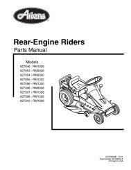
CONTROLS AND FEATURESENGLISH1. Traction Drive ClutchLever2. Throttle (Engine Stop)3. Choke Control Knob4. Differential Lock(924122, 332, 505, 506,508)5. Ignition Key, push-pull(924121, 122)6. Primer Bulb7. Muffler Guard8. Discharge ChuteDeflector9. Runner10. Solenoid Compartment(924332, 505, 506, 508)11. Battery Cover andBattery(924332, 505, 506, 508)12. Axle Lock Pin (924121)13. Belt Cover14. Wing Knobs15. Headlight16. Discharge Chute17. Electric Chute Motor(924505, 506)18. Impeller19. Scraper Blade20. Auger Gearcase21. Auger22. Recoil Starter Handle23. Electric Starter(924121, 122)24. Attachment Clutch Lever25. Chute Rotation Switch(924505, 506)26. Deflector Remote Control(924121, 505, 506)27. Speed Selector28. Chute Crank(924121, 122, 332, 508)29. Ignition Key(924332, 505, 506, 508)30. Heated Handles Switch31. Heated Handles32. Fuel Shut-off ValveFRANÇAIS1. Levier d’embrayagede la traction2. Commande des gaz(arrêt du moteur)3. Bouton du Starter4. Blocage du différentiel(924122, 332, 505, 506,508)5. Clé de contact,pousser-tirer (924121,122)6. Poire d’amorçage7. Garant du silencieux8. Déflecteur de la goulotted’évacuation9. Patin10. Compartiment dusolénoïde (924332, 505,506, 508)11. Couvercle de batterieet batterie (924332, 505,506, 508)12. Broche de blocage del’essieu (924121)13. Couvercle de la courroie14. Boutons15. Phare16. Goulotte d’évacuation17. Moteur électrique de lagoulotte (924505, 506)18. Turbine19. Lame racleuse20. Boîtier de renvoi du rotor21. Rotor22. Poignée du démarreurà cordon23. Démarreur électrique(924121, 122)24. Levier d’embrayage del’outil25. Commande de rotationde la goulotte (924505,506)26. Commande à distancedu déflecteur (924121,505, 506)27. Sélecteur de vitesse28. Manivelle de la goulotte(924121, 122, 332, 508)29. Clé de contact (924332,505, 506, 508)30. Poignées chauffées31. Commande de poignéeschauffées32. Robinet de carburantESPAÑOL1. Palanca del embraguede la transmisión de latracción2. Aceleración (parada demotor)3. Perilla de control delEstrangulador4. Traba del diferencial(924122, 332, 505, 506,508)5. Llave de encendido, tiroempujel(924121, 122)6. Botón del cebador7. Protector del silenciador8. Deflector de la tolva dedescarga9. Guía10. Compartimento delsolenoide (924332, 505,506, 508)11. Cubierta de la bateríay batería (924332, 505,506, 508)12. Pasador de traba del eje(924121)13. Cubierta de la correa14. Perillas de mariposa15. Luces delanteras16. Tolva de descarga17. Motor de la tolvaeléctrica (924505, 506)18. Propulsor19. Cuchilla raspadora20. Caja de engranajes delsinfín21. Sinfín22. Manilla de retroceso delmotor de arranque23. Arranque eléctrico(924121, 122)24. Palanca del embraguedel accesorio25. Interruptor de rotación dela tolva (924505, 506)26. Control remoto deldeflector (924121, 505,506)27. Selector de velocidad28. Manivela de la tolva(924121, 122, 332, 508)29. Llave de encendido(924332, 505, 506, 508)30. Interruptor de lasmanillas térmicas31. Manillas térmicas32. Válvula de corte delcombustible4
1617181514321312111092120198763245222324131302928 27 26Figure 125OS05955
DELIVERYCustomer Note: If you have purchased thisproduct without complete assembly andinstruction by your retailer, it is yourresponsibility to:1. Read and understand all assemblyinstructions in this manual. If you do notunderstand or have difficulty following theinstructions, contact your nearest <strong>Ariens</strong>Dealer for assistance. Make sure allassembly has been properly completed.NOTE: To locate your nearest <strong>Ariens</strong> Dealer,call 1-800-678-5443 or go to www.ariens.comon the internet.2. Understand all Safety Precautionsprovided in the manuals.3. Review control functions and operation ofthe unit. Do not operate the <strong>Sno</strong>-Throunless all controls function as describedin this manual.4. Review recommended lubrication,maintenance and adjustments.5. Review Limited Warranty Policy.6. Fill out a Product Registration Card andreturn the card to the <strong>Ariens</strong> Company orgo to www.ariens.com.WARNING: Improper assembly oradjustments can cause serious injury.SAFETYWARNING: To avoid injury to handsand feet, always disengage clutches,shut off engine, and wait for allmovement to stop before uncloggingor working on snow thrower.Keep hands and feet away from augerand impeller.SAFETY ALERTSLook for these symbols to pointout important safety precautions.They mean:Attention!Personal Safety IsInvolved!Become Alert!Obey The Message!The safety alert symbols above and signalwords below are used on decals and in thismanual. Read and understand all safetymessages.DANGER: IMMINENTLYHAZARDOUS SITUATION! If notavoided, WILL RESULT in death orserious injury.WARNING: POTENTIALLYHAZARDOUS SITUATION! If notavoided, COULD RESULT in death orserious injury.CAUTION: POTENTIALLYHAZARDOUS SITUATION! If notavoided, MAY RESULT in minor ormoderate injury. It may also be used toalert against unsafe practices.NOTATIONSNOTE: General reference information forproper operation and maintenance practices.IMPORTANT: Specific procedures orinformation required to prevent damage to unitor attachment.PRACTICES AND LAWSPractice usual and customary safe workingprecautions, for the benefit of yourself andothers. Understand and follow all safetymessages. Be alert to unsafe conditions andthe possibility of minor, moderate, or seriousinjury or death. Learn applicable rules andlaws in your area. Always follow the practicesset forth in this manual.REQUIRED OPERATOR TRAININGOriginal purchaser of this unit was instructedby the seller on safe and proper operation. Ifunit is to be used by someone other thanoriginal purchaser; loaned, rented or sold,ALWAYS provide this manual and any neededsafety training before operation.GB - 7
SAFETY DECALS ANDLOCATIONSALWAYS replace missing or damaged SafetyDecals. Refer to figure below for Safety Decallocations.231Figure 3OS23601. DANGER! 2. WARNING!OS2080ROTATING PARTS.Keep clear of auger while engineis running.• Read Operator’s Manual.• Allow operation only byproperly trained adult, neverchildren.• Stop engine and removeignition key prior to leavingthe operator’s position forany reason.• Keep all controls, guards andsafety devices properlyserviced and functional.• Never direct dischargetowards persons or propertythat may be injured ordamaged by thrown objects.OL1801OL4370OL0910Read Owner/Operator Manual.Keep people away from unit whileoperating. Keep children out ofwork area and under watchfulcare of a responsible adult.Never direct discharge towardspersons or property that may beinjured or damaged by thrownobjects.GB - 8
OL4010OL46903. DANGER!OS2070Stop engine, remove key, readmanual before making anyrepairs, adjustments.Wear appropriate hearingprotection.ROTATING PARTS! Stop engineand remove key before clearing.High speed impeller rotatesbelow discharge opening. Waitfor all moving parts to stopbefore removing clogs orservicing.SAFETY RULESRead, understand, and follow all safetypractices in Owner/Operator Manual beforebeginning assembly or operating. Failure tofollow instructions could result in personalinjury and/or damage to unit.ALWAYS remove key and/or wire from sparkplug before assembly, maintenance or service.Unintentional engine start up can cause deathor serious injury.Complete a walk around inspection of unit andwork area to understand:• Work area • Your unit • All safety decalsALWAYS check overhead and side clearancescarefully before operation. ALWAYS be awareof traffic when operating along streets orcurbs.Keep children and people away. Keep childrenout of work area and under watchful care of aresponsible adult.NEVER allow children to operate or play on ornear unit. Be alert and shut off unit if childrenenter area.DO NOT allow adults to operate unit withoutproper training.Keep area of operation clear of all toys, pets,and debris. Thrown objects can cause injury.Check for weak spots on docks, ramps orfloors. Avoid uneven work areas and roughterrain. Stay alert for hidden hazards.Avoid uneven and rough terrain. DO NOToperate near drop offs, ditches, orembankments. Unit can suddenly turn over if awheel is over the edge of a cliff or ditch, or ifan edge caves in.Falling snow, fog, etc. can reduce vision andcause an accident. Operate unit only whenthere is good visibility and light.Only trained adults may operate unit.Training includes actual operation.NEVER operate unit after or during the use ofmedication, drugs or alcohol. Safe operationrequires your complete and unimpairedattention at all times.NEVER allow anyone to operate this unitwhen their alertness or coordination isimpaired.DO NOT operate unit without wearingadequate winter outer garments. Wearadequate safety gear, including safety glasseswith side shields, and protective gloves. Wearproper footwear to improve footing on slipperysurfaces.DO NOT wear loose clothing or jewelry and tieback hair that may get caught in rotating parts.Protect eyes, face and head from objects thatmay be thrown from unit. Wear appropriatehearing protection.Avoid sharp edges. Sharp edges can cut.Moving parts can cut off fingers or a hand.ALWAYS keep hands and feet away from allrotating parts during operation. Rotating partscan cut off body parts.NEVER place your hands or any part of yourbody or clothing inside or near any movingpart while unit is running.ALWAYS keep hands away from all pinchpoints.DO NOT touch unit parts which might be hotfrom operation. Allow parts to cool beforeattempting to maintain, adjust or service.Never direct discharge towards persons orproperty that may be injured or damaged bythrown objects. Use extreme caution on gravelsurfaces. Stay alert for hidden hazards ortraffic. Adjust Runners so Scraper Blade doesnot contact gravel.DO NOT throw snow any higher thannecessary.Deflected materials can cause injury andproperty damage.Always stand clear of the discharge area whenoperating this unit.GB - 9
Never fill containers inside a vehicle or on atruck or trailer bed with a plastic liner. Alwaysplace containers on the ground away fromyour vehicle before filling.When practical, remove gas-poweredequipment from the truck or trailer and refuel iton the ground. If this is not possible, thenrefuel such equipment on a trailer with aportable container, rather than from a gasolinedispenser nozzle.Keep the nozzle in contact with the rim of thefuel tank or container opening at all times untilfueling is complete. Do not use a nozzlelock-open device.If fuel is spilled on clothing, change clothingimmediately.Avoid Electric Shock. Objects contacting bothbattery terminals at the same time may resultin injury and unit damage. DO NOT reversebattery connections.Explosive Gases from battery can cause deathor serious injury. Poisonous battery fluidcontains sulfuric acid and its contact with skin,eyes or clothing can cause severe chemicalburns.No flames, No sparks, No smoking nearbattery.ALWAYS wear safety glasses and protectivegear near battery.DO NOT TIP battery beyond a 45° angle inany direction.ALWAYS keep batteries out of reach ofchildren.Battery posts, terminals and relatedaccessories contain lead and leadcompounds, chemicals known to the State ofCalifornia to cause cancer and reproductiveharm. Wash hands after handling.Follow First Aid directions for contact withbattery fluid.• External Contact: Flush with water.• Eyes: Flush with water for at least 15minutes and get medical attentionimmediately!• Internal Contact: Drink large quantities ofwater. Follow with Milk of Magnesia,beaten egg or vegetable oil. Get medicalattention immediately!• In case of internal contact, DO NOTinduce vomiting!Before tipping unit up onto housing, removefuel so no spills will occur and remove battery.Ensure unit is secure and will not tip overduring maintenance.ALWAYS keep protective structures, guards,and panels in good repair, in place andsecurely fastened. NEVER modify or removesafety devices.DO NOT change engine governor settings orover-speed engine.Fumes from engine exhaust can cause injuryor death. DO NOT run engine in an enclosedarea. Always provide good ventilation.ALWAYS maintain unit in safe operatingcondition. Damaged or worn out muffler cancause fire or explosion.Keep all hardware properly tightened. Checkshear bolts frequently.Maintain or replace safety and instructionlabels, as necessary.NEVER store unit with fuel in fuel tank, insidea building where any ignition sources arepresent.Shut off fuel and allow engine to coolcompletely before storing in closed area orcovering unit.For extended storage, clean unit thoroughly.See Engine Manual for proper storage.Use only attachments or accessories designedfor your unit.Check components frequently. If worn ordamaged, replace with manufacturer’srecommended parts.WARNING: AVOID INJURY. Readand understand the entire Safetysection before proceeding.WARNING: Dropping or tipping overboxed unit could result in personalinjury or damage to unit.ASSEMBLYTools Required:• Pliers• Open-End Wrenches: 3/8, 7/16, 1/2, 9/16"and/or Adjustable Wrench• Tire GaugeGB - 11
PACKAGE CONTENTSChute Crank (924121,122,118, 332, 508, 551)DischargeChute4522361LiteraturePackASSEMBLYFigure 4Handlebar and Shift Rod<strong>Sno</strong>-ThroUnitOS16421. Remove lower wing knobs on handlebarassembly (Figure 5).2. Remove upper wing nut and bolt on shiftrod.3. Loosen upper wing knobs on handlebar.4. Loosen lower wing nut and bolt on shiftrod.5. Put speed selector lever into fastestreverse panel notch.6. Rotate handlebar up so wing knob holesalign. Install and tighten all wing knobs.7. Install wing nut and bolt removed in step 2onto shift rod and tighten hardware.1. HandlebarAssembly2. Wing Knobs3. Wing NutOS09014. Speed Selector5. Bolt6. Shift RodFigure 5Install Discharge Chute and Crank(924118, 121, 122, 332, 508, 551)Figure 6.1. Grease discharge chute ring on blowerhousing (if not already greased).2. Remove mounting hardware from top ofengine.3. Slide chute ring under retainer clip onblower housing and put chute on housing.4. Secure chute by fastening chute strap toengine with hardware just removed.NOTE: Washers and lock nuts go on top ofchute strap.5. Loosen mounting nut on chute and movechute up or down so that chute ring isapproximately centered between retainerclip and lower ring and tighten.6. Slide chute crank rod through bracketunder handlebar and through hole inpanel.7. Align chute crank rod with the universaljoint on chute and fasten with spring clip.8. Slide the bracket under handlebar up ordown until the chute crank rod is centeredin the panel and then tighten the brackethardware.GB - 12
1112113109283276451. Pinion Bracket2. Gear Strap3. Chute Bracket4. Retainer Clip5. Lower Ring6. Chute RingFigure 6DS01127. Mounting Nut8. Flat Gear9. Pinion10.Chute Strap11.Universal Joint12.Spring ClipInstall Discharge Chute - ElectricRotation (924505, 506)1. Remove chute motor cover.2. Remove the six (6) nuts from ring gear(Figure 7).3. Remove two (2) half rings.4. Position Discharge Chute over threadedstuds with the chute opening facing theelectric motor.5. Replace the half rings.6. Replace the six (6) nuts and tighten to120 lbf-in. (13.56 N•m) torque.7. Replace chute motor cover.1. Ring Gear Nuts2. Half Rings3. Discharge ChuteFigure 7OS1930Connect Battery (924332, 505, 506,508)1. Remove wing nuts from battery cover.2. Install wire lead to battery terminal.3. Install battery cover and tighten wingnuts.Deflector Remote (924121, 122, 332,505, 506, 508)1. Slide cable end through hole on bracketon left side of chute (Figure 8).2. Attach cable eye to stud on deflector.Hold in place with flat washer and e-ring.3. Check deflector travel. Adjust nut oncable end under handlebar to obtain fulltravel. (See Deflector Remote in Serviceand Adjustments.)GB - 13
1. Cable Eye2. Flat Washer and E-Ring3. Deflector CableFigure 8OS1981Check Function of Dual HandleInterlockWithout the engine running, press down(engage) both clutch levers. Releaseattachment clutch lever. Attachment clutchshould remain engaged until traction clutchlever is released, then both clutches mustdisengage. If they do not, contact your dealerfor repairs.Check Tire PressureCheck tire pressure and adjust to the pressurelisted on tire sidewall.CONTROLS AND FEATURESSee Figure 1 for all Controls and Featureslocations.Dual Handle InterlockWhen Attachment Clutch and then TractionDrive Clutch are engaged, the AttachmentClutch will remain engaged (lever down) ifreleased. To stop attachment, release TractionDrive Clutch and both clutches will disengage.12 3WARNING: AVOID INJURY. Readand understand the entire Safetysection before proceeding.WARNING: To avoid injury to handsand feet, always disengage clutches,shut off engine, and wait for allmovement to stop before uncloggingor working on snow thrower.Keep hands and feet away from augerand impeller.OPERATIONCheck Auger Gearcase OilCheck oil level in auger gearcase (see Serviceand Adjustments).Check Engine Crankcase OilIMPORTANT: The engine is shipped with5W-30 oil in crankcase. Refer to EngineManual for detailed instructions.Fill Engine Fuel TankRefer to Engine Manual for proper fuel typeand tank capacity.Check Function of all ControlsEnsure unit runs and performs properly. Referto Operation.Run-in Attachment Belt1. Start unit in a well-ventilated areaaccording to Starting and Shut-Off inOperation.2. Engage attachment clutch lever and runattachment for about 15 minutes.3. Stop unit, wait for all moving parts to stop,and remove spark plug wire.4. Adjust clutch according to AttachmentClutch/Brake Adjustment in Service andAdjustments.Traction Drive Clutch - Left HandLeverSqueeze the TractionDrive Clutch Lever2against the Handlebar(1) to engage wheeldrive for propelling unit.Forward speed will varyaccording to snow depth1and moisture content.Release lever (2) toOL2701stop movement.NOTE: When traveling to or from the area tobe cleared, press down on the handlebarsenough to raise the front of the unit slightly offthe surface. Engage the traction drive clutchwithout engaging the attachment drive clutch.GB - 14
Attachment Clutch - Right Hand LeverSqueeze Attachment2 Clutch Lever againsthandlebar (1) to engageattachment. Releaseboth clutch levers (2) todisengage power andapply brake to1 attachment.IMPORTANT: If the beltsqueals when theOL2691attachment clutch leveris engaged, theattachment drive may be frozen. Immediatelyrelease the attachment clutch lever and movethe unit into a heated area to thaw.Ignition Switch (120V start on engine)Key Switch has two positions:1. “Stop” - pulled out2. Run - pushed in2 NOTE: DO NOT twist key afterit is inserted.1OS1431Ignition Switch (12V start on dashpanel)1The ignition switch is2 operated by a removable key.It has three positions:3 1.Stop2.Run3.StartOS0232Primer BulbPushing the primer bulb in addsfuel for easier engine start.Refer to Starting and Shut Off.OS1321Speed SelectorThe Speed Selector controls the unit travel in aforward or reverse direction when positionedin notch of speed.Forward:6(6) Fastest5(1) SlowReverse:4(1) Slow3(2) Fast21IMPORTANT: DO NOTchange motion fromforward to reverse withclutch engaged.Forward speed can be1changed withoutdeclutching.2Choke Control Knob1. Choke Closed position:chokes off air to engine foreasier start.21OS13322. Choke Open position:allows for normaloperation.IMPORTANT: Graduallyopen choke after enginestarts.ThrottleSTOP1234OL2720OS1191The throttle controls the enginespeed. To increase or decreasethe engine speed, adjust to:1. Fast (normal or warm starts)2. Part-Throttle3. Slow (cold weather starts)4. Stop (engine is off)Electric StarterThe electric starter will start a properly chokedand cranked engine when the key is turned(12V) or starter button (120V) is pushed. Referto Starting and Shut-Off.Recoil Starter HandleWhen pulled, handle will turn engine over.IMPORTANT: DO NOT let handle snap backagainst starter.GB - 15
Discharge Chute DeflectorALWAYS position discharge chute deflector ata safe angle before starting engine.DO NOT throw snow any higher thannecessary.Push deflector handle forward or down tothrow snow lower. Pull deflector handle up orto the rear to throw snow higher.IMPORTANT: If Chute Deflector does not stayin set position, adjust as directed in Serviceand Adjustments, or repair before operation.Deflector Remote (924121, 332, 505,506)Place deflector into position before operation.DO NOT throw snow any higher thannecessary.Push deflector remote forward to throw snowhigher. Pull deflector remote back to throwsnow lower.Discharge ChuteDischarge chute rotates 220°.ALWAYS position discharge chute in safedirection and angle, away from operator andbystanders, before starting engine.Chute Crank (924121, 122, 332, 508)IMPORTANT: If chute does not stay in setposition, adjust as directed in Service andAdjustments, or repair before operation.Rotate the Chute with Discharge Chute CrankHandle.IMPORTANT: DO NOT force frozen chutecontrols. Start engine and run for 3-5 minutesto thaw. If still frozen, take to warm place untilcontrols are free.Chute Rotation Switch (924505, 506)21Differential Lock (924118, 122, 332,505, 506, 508, 551)Differential Lock knob is located1on the Left Wheel Hub. Withdifferential locked power isapplied equally to both wheels.To engage differential lock:2• Pull and turn knob to LOCKED(1) position and release (knobwill snap in place whenpositioned correctly).OL2730 To resume differential action fortransport:• Pull and turn knob to UNLOCKED (2)position and release.Axle Lock Pin (Figure 9) (924121)Use the axle lock pin to lock or unlock the rightwheel. Lock the right wheel to increasetraction; unlock the right wheel to allow foreasier turning of the unit.Wheel UnlockedWheel LockedAxleLockPinOS1970Press the chute rotation switch right (1) torotate chute clockwise. Press the chuterotation switch left (2) to rotate chutecounterclockwise.Heated HandlesTurn the heated handles1switch to the ON (1) positionto activate. Turn the switchto the OFF (2) position todeactivate.2OS1950Figure 9GB - 16
Scraper BladeThe scraper blade allows the back of thehousing to keep better contact with the surfacebeing cleared. It also prevents damage to thehousing from normal wear.IMPORTANT: DO NOT allow Scraper Blade towear too far or Auger/Impeller housing willbecome damaged.RunnersThe runners control the distance between thescraper blade and the ground. Adjust runnersequally to keep blade level with the ground.Refer to Pre-Start for recommended settings.FILLING FUEL TANKWARNING: AVOID INJURY. Readand understand the entire Safetysection before proceeding.Fuel Shut-Off ValveIMPORTANT: The fuel shut-off valve MUST bein the closed position prior to transporting theunit.The fuel shut-off valve has two positions:• Closed Position: Use this position toservice, transport, or store the unit.• Open Position: Use this position to run theunit.To add fuel to fuel tank:1. ALWAYS place unit in open or wellventilated area.2. Stop engine and allow to cool.3. Clean Fuel Cap and surrounding area toprevent dirt from entering Fuel Tank.4. Remove Cap.IMPORTANT: DO NOT use gasohol orgasoline containing alcohol. See EngineManual for correct type and grade of fuel.5. Fill fuel tank to within 1/2 in. (1.2 cm)below bottom of filler neck with unleadedgasoline.NOTE: Tank capacity is 1 gallon (3.8 liters).6. Replace Fuel Cap and tighten.7. ALWAYS clean up any spilled fuel.PRE-START1. Frozen ImpellerIMPORTANT: Before starting engine, checkimpeller to be sure it is not frozen.To check impeller:1. With key in “Stop” position, squeezeAttachment Clutch Lever to Engagedposition.2. Pull Recoil Starter Handle.3. If Impeller is frozen, (cannot pull StarterHandle) move unit to a heated area andthaw to prevent possible damage.2. Check Dual Handle InterlockWithout the engine running, press down(engage) both clutch levers. Releaseattachment clutch lever. Attachment clutchshould remain engaged until traction clutchlever is released, then both clutches mustdisengage.If clutches do not engage or disengageproperly, adjust or repair before operation (seeService and Adjustments).3. Differential Lock (924118, 22, 332,505, 506, 508, 551)ALWAYS engage differential lock (located inleft wheel hub) for best traction when throwingsnow.4. Adjust Axle Lock (924121)Use the axle lock pin to lock or unlock the rightwheel. Lock the right wheel to increasetraction; unlock the right wheel to allow foreasier turning of the unit.5. Adjust RunnersCheck and adjust Runners (see Service andAdjustments). Allow 1/8 in. (3 mm) betweenscraper blade and hard, smooth surface(s).Allow 1-1/4 in. (30 mm) between scraperblade and uneven or gravel surfaces.6. Check Engine Fuel & Crankcase OilWARNING: AVOID INJURY. Readand understand the entire Safetysection before proceeding.Check and add fuel if required. Check that theengine crankcase oil is full using dipstick.Refer to Engine Manual for detailedinstructions.TO STOP IN AN EMERGENCYImmediately release both control levers to stopunit in an emergency. Stop engine, removekey and wait for all rotating parts to stop beforeleaving operator’s position.GB - 17
STARTING AND SHUT OFFWARNING: FAILURE TO FOLLOWINSTRUCTIONS could result inpersonal injury and/or damage tounit. DO NOT attempt to start yourunit at this time. Read entireOwner/Operator Manual and theEngine Manual first.IMPORTANT: Allow unit and engine to adjustto the outdoor temperatures before clearingsnow. Before shut-off, run the attachment afew minutes to prevent freeze-up.NOTE: Try out each control without the enginerunning to see how it works and what it does.Manual Start1. Turn discharge chute straight ahead.2. Make sure that the traction clutch andattachment drive clutch levers are fullydisengaged.3. Push Primer Bulb 2 or 3 times for coldengine.NOTE: When temperature is below -15° F(-26° C) additional priming may be needed.4. If engine is cold, apply choke. See EngineManual for detailed instructions.NOTE: A warm engine requires less chokingthan a cold engine.5. Set throttle to proper starting position.6. Insert key into ignition switch.12V - Turn key into RUN position.120V - Push key into RUN position. DONOT twist key after it is inserted.7. Grasp starter handle and pull rope outslowly until it pulls harder. Let rope rewindslowly.8. Pull rope with a rapid continuous full armstroke. Let rope rewind slowly.IMPORTANT: DO NOT let Starter Handlesnap against Starter.9. Repeat steps 7 and 8 until engine starts.(If engine does not start, refer toTroubleshooting.)10. Adjust choke as needed.11. Set throttle to Part Throttle or Slowposition for adaptation to outsidetemperature or travel. Set throttle to Fastposition for normal operation.Electric Start1. Connect extension cord to prongs onstarter.IMPORTANT: Prevent damage to unit. Knowvoltage of your starter and only use matchingoutlets.2. Plug extension into 120V 3-wire,grounded outlet.3. Turn discharge chute straight ahead.4. Make sure that the traction clutch andattachment drive clutch levers are fullydisengaged.5. Push Primer Bulb 2 or 3 times for coldengine.NOTE: When temperature is below -15° F(-26° C) additional priming may be needed.6. Insert key into ignition switch on engineand push into "Run" position. DO NOTtwist key after it is inserted.7. If engine is cold, apply choke. A warmengine requires less choking than a coldengine. See Engine Manual for detailedinstructions.8. Set throttle to proper starting position.9. Press starter button on engine untilengine starts.IMPORTANT: DO NOT operate starter morethan 15 seconds per minute, as overheatingand damage can occur. (If engine does notstart, refer to Troubleshooting.)10. Adjust choke as needed.11. Disconnect power cord from outlet, thenstarter.12. Set throttle to Part Throttle or Slowposition for travel or adaptation to outsidetemperature. Once achieved, set throttleto Fast position for normal operation.Electric Start (12V)1. Turn discharge chute straight ahead.2. Make sure that the traction clutch andattachment drive clutch levers are fullydisengaged.3. Push Primer Bulb 2 or 3 times for coldengine.NOTE: When temperature is below -15° F(-26° C) additional priming may be needed.4. If engine is cold, apply choke. See EngineManual for detailed instructions.NOTE: A warm engine requires less chokingthan a cold engine.5. Set throttle to proper starting position.6. Put ignition key into START position untilengine starts and release into the RUNposition.GB - 18
IMPORTANT: DO NOT operate starter morethan 15 seconds per minute, as overheatingand damage can occur. (If engine does notstart, refer to Troubleshooting.)7. Adjust choke as needed.8. Set throttle to Part Throttle or Slowposition for travel or adaptation to outsidetemperature. Once achieved, set throttleto Fast position for normal operation.Shut Off1. Release Traction Drive Clutch Lever andallow unit to come to a complete stop.2. Run Impeller a few minutes after use toprevent freeze-up of Impeller.3. Release Attachment Clutch Lever andwait for all moving parts to come to acomplete stop.4. Move Throttle to the “Stop” position.5. Remove key.SNOW REMOVALIMPORTANT: Allow unit and engine to adjustto the outdoor temperatures before clearingsnow.NOTE: Attachment clutch should be engagedbefore wheel drive clutch when throwing snow.1. Select Speed Control position anddirection.2. Engage Attachment Clutch - Right HandLever.3. Engage Traction Drive Clutch - Left HandLever.IMPORTANT: DO NOT overload unit capacityby attempting to clear snow at too fast a rate.Use slow speed to clear deep or hard packedsnow.<strong>Ariens</strong> Dealers will provide any service oradjustments which may be required to keepyour unit operating at peak efficiency. Shouldengine service be required, contact an <strong>Ariens</strong>dealer or an authorized engine manufacturer'sservice center.WARNING: AVOID INJURY. Readand understand the entire Safetysection before proceeding.SERVICE POSITIONWARNING: Before tipping unit uponto housing, remove fuel so nospills will occur and remove battery(if equipped). Ensure unit is secureand will not tip over duringmaintenance.MAINTENANCETips for Operation<strong>Sno</strong>w is best removed as soon as possibleafter snow fall.To clear an area, run unit in an overlappingseries of paths. For large areas; start in themiddle and throw snow to each side, so snowis not cleared more than once.ALWAYS direct snow away from area to becleared and with direction of the wind.TRAVELINGTo travel from one work area to another:1. Set Throttle to Slow or Part-Throttleposition.2. Press down on handlebars enough toraise front of unit slightly off surface.3. Engage wheel drive clutch withoutengaging attachment drive clutch.TRANSPORTALWAYS shut off engine, remove key, andclose fuel shut-off valve when transporting uniton a truck or trailer.Use extra care when loading or unloading unitonto trailer or truck.Secure unit chassis to transport vehicle.NEVER secure from rods or linkages thatcould be damaged.DO NOT transport machine while engine isrunning.Place unit on a flat level surface. Tip unitforward onto front of impeller housing forservice. Assure unit is secure and will not tipover. Strap and clamp onto bench if needed.MAINTENANCE SCHEDULEThe chart below shows the recommendedmaintenance schedule that should beperformed on a regular basis. More frequentservice may be required.GB - 19
MAINTENANCE SCHEDULEServicePerformedCheck DualHandleInterlockCheckFastenersCheckClutchesClean EngineCheck EngineOilEachUse••••Every5 hrs.•* After first two hours of operation.Every25hrs.ChangeEngine Oil*•Check TirePressureCheck AugerGearcaseGeneralLubricationBatteryMaintenance•Yearly• •• •• •CHECK DUAL HANDLEINTERLOCKWithout the engine running, press down(engage) both clutch levers. Releaseattachment clutch lever. Attachment clutchshould remain engaged until traction clutchlever is released, then both clutches mustdisengage.CHECK FASTENERSMake sure all hardware is tightened properly.CLEAN ENGINERefer to Engine Manual for detailedinstructions.CHECK ENGINE OILThe engine crankcase oil should be checkedevery 5 hours of operation. Oil level MUST bemaintained in safe operating range on dipstickat all times or engine damage will result (SeeEngine Manual).Park unit on a level surface. Refer to EngineManual for detailed instructions.CHANGE ENGINE OILChange oil after first 2 hours of operation,thereafter change oil every 25 hours (moreoften if required). Refer to Engine Manual fordetailed instructions.Run engine just prior to changing oil. Warm oilwill flow more freely and carry away morecontamination.CHECK TIRE PRESSUREKeep tires at pressure listed on the tiresidewall.CHECK AUGER GEARCASEIMPORTANT: Proper oil level must bemaintained.Gear cases are filled to the correct level at thefactory. Unless there is evidence of leakage,no additional lubricant should be required.Check oil level each season or every 25 hoursof operation.To ensure adequate lubricant level:1. Remove filler plug (Figure 10). Lubricantmust be at least up to bottom of lubricantfiller hole with unit resting on alevel-surface.2. Add lubricant if required. Allow oil to drainto level of plug and replace plug.IMPORTANT: Use only <strong>Ariens</strong> special gearlubricant L-2 (Part Number 00008000).CHECK CLUTCHESAuger / impeller must stop within 5 secondswhen attachment clutch/impeller brake lever isreleased.Wheels must stop quickly when traction driveclutch lever is released.If clutches do not engage or disengageproperly, adjust or repair before operation (seeService and Adjustments).GB - 20
11. Auger Gearcase - Cast Iron2. Oil Fill and Drain Plug3. Auger Gearcase - Aluminum23Figure 1022GENERAL LUBRICATIONIMPORTANT: Wipe each fitting clean beforeand after lubrication.IMPORTANT: DO NOT allow grease or oil toget on friction disc, friction plate or belts.NOTE: Apply Stens Mix Hi-Temp Grease orequivalent to the lubrication fittings. SeeService Parts.<strong>Sno</strong>-Thro should be lubricated (Figure 11) atbeginning of season or every 25 operatinghours.Auger ShaftNOTE: To grease auger shaft, remove shearbolt nuts, and shear bolts. Turn auger on shaftwhile applying grease at zerk fittings. Replaceshear bolt per instructions in Service andAdjustments.861 11175431. Auger and Shaft2. Discharge Chute3. Sprocket/PinionAssembly4. Axle ShaftFigure 115. Shift Lever Arm6. Pinion Chain7. Hex Shaft8. Shift LinkGreaseOilOS0641OS0741CLEAN BATTERY (924332, 505,506, 508)WARNING: AVOID INJURY. Readand understand the entire Safetysection before proceeding.IMPORTANT: Battery is maintenance free. Donot tamper with or attempt to open battery.See Service and Adjustments for chargingprocedures.TerminalsKeep battery and its terminals clean.IMPORTANT: Remove battery from unitbefore cleaning.Remove corrosion from battery terminals andcable connections with a wire brush, thenwash with a weak baking soda solution.After cleaning, apply a thin coat of grease orpetroleum jelly to terminals and cable ends toretard corrosion.GB - 21
DISCHARGE CHUTE DEFLECTOR(924118, 551)Deflector must stay in selected position whilethrowing snow.To adjust, loosen then retighten hardware todesired deflector drag force (Figure 12).SERVICE AND ADJUSTMENTSWARNING: AVOID INJURY. Readand understand the entire Safetysection before proceeding.Adjusting HardwareDischarge ChuteDeflectorIf deflector does not follow full range of travel:1. Push deflector remote all the wayforward.2. Loosen adjusting nuts on cable supportbracket.3. To adjust the deflector lower:Slide cable down. Tighten bottom nut.4. To adjust deflector higher:Slide cable up. Tighten top nut.5. Check travel and repeat adjustment asnecessary.DISCHARGE CHUTEIf chute does not stay in position whileoperating, tighten nut on carriage bolt at pivotpoint to increase tension on spring (Figure 14).Smooth and easy rotation of properlylubricated chute with crank is obtained byadjusting pinion and chute gear teeth so theymesh together.Figure 12OS0113DEFLECTOR REMOTE (924121,122, 332, 505, 506, 508)Deflector must stay in selected position whilethrowing snow.If deflector does not stay in set position:1. Tighten nut beneath the control panel toincrease friction on pressure flange(Figure 13).12341. Pinion2. Chute Gear3. Carriage Bolt4. SpringDS01134 Figure 14121. Nut2. Pressure Flange3. Adjusting Nuts4. Cable Support Bracket3Figure 13OS0280RUNNERSRunners should be adjusted (Figure 15) asconditions require.1. Position unit on a hard, flat, smooth levelsurface.2. Adjust runners by inserting a spacer ofdesired thickness under center of scraperblade, loosen runner hardware, sliderunners to flat surface. Allow 1/8 in.(3 mm) between scraper blade and hardsmooth surfaces. Allow 1-1/4 in. (30 mm)between scraper blade and uneven orgravel surfaces. Retighten hardware.GB - 22
NOTE: Keep housing level by adjustingrunners equally.3211. Runner2. Runner HardwareFigure 15SCRAPER BLADEIMPORTANT: Damage to auger/impellerhousing will result if blade wears down too far.Scraper blade is adjustable to compensate forwear.To adjust scraper blade:1. Tip unit back onto handlebar, supporthousing and loosen nuts retaining blade.2. Adjust runners to fully raised position(housing closest to ground).3. Reposition scraper blade flush withrunners and tighten lock nuts.SHEAR BOLTSIMPORTANT: Use only <strong>Ariens</strong> shear bolts forreplacement. Use of any other type of shearbolt may result in severe damage to unit.Occasionally a foreign object may enter theauger/impeller housing and jam the auger,breaking shear bolts (Figure 16) which securethe auger to the shaft. This allows auger toturn freely on the shaft preventing damage togear drive.For Replacement:1. Slide auger outward against roll pin andalign hole in shaft with hole in auger(holes in shaft for roll pins and shear boltsline up).2. Drive shear bolt through hole (if shear boltwas broken this will drive remaining partfrom shaft).3. Secure shear bolt with nut.121. Auger2. Shear Bolts3. Roll PinFigure 16OS0402SPEED SELECTOR ADJUSTMENTTo adjust (Figure 17):1. Place unit into service position.2. Remove hair pin from adjustment pivotpin.3. Pull shift rod and pin out of speed selectorlever.4. Place the speed selector in the fastestreverse speed position.5. Pull the shift rod straight up towards thecontrol panel as far as it will go.6. Thread the adjustment pivot pin along theshift rod until it aligns with the mating holeon the speed selector lever. Insert thepivot pin into hole.7. Make sure the speed selector shifts intoeach speed position.8. Secure adjustment pivot pin with hairpin.GB - 23
2131. Shift Rod2. Adjustment Pivot Pin3. Speed Selector Lever4. HairpinFigure 174ATTACHMENT CLUTCH/BRAKEADJUSTMENT(Figures 18 and 19)IMPORTANT: IMPROPERADJUSTMENT could result inunexpected movement of auger andimpeller causing death or seriousinjury. Auger / impeller must stopwithin 5 seconds when AttachmentClutch/Impeller Brake lever isreleased.1. Remove belt cover.2. Check belt alignment (Figure 21).Engine sheave and attachment pulleymust align vertically. Also, belt must becentered in the idler pulley.To align, move attachment pulley:a.Loosen set screws.b.Slide pulley and key to desiredposition.c.Tighten set screws.3. Install belt cover.4. Adjust cable slack.IMPORTANT: The belt cover must be installedand the clutch cable must be slack when thelever is disengaged.a.With clutch lever disengaged, loosenjam nut on cable adjuster.b.Turn adjuster body to remove all slackfrom the cable. Do not stretch springor move lower clutch arm.c.Turn back the adjuster body 5 turns(approximately 1/4 in. or 6 mm).Finger tighten jam nut.d.Hold adjuster body with pliers andtighten jam nut with wrench.5. Check spring length.a.Measure the length of the clutch cablespring.b.Engage and hold the attachmentclutch lever.c.Measure the length of the springagain. The spring should be7/16 –11/16 in. (11.1–17.5 mm) longerwhen the lever is engaged.GB - 24
6. Adjust spring length.NOTE: Approximately 1/8 in. (3 mm)movement of the idler will change springextension by 1/8 in. (3 mm).a.Loosen the idler adjustment nut.b.To increase spring extension, moveidler towards belt (Figure 21).c.To decrease spring extension, moveidler away from belt.d.Tighten idler adjustment nut.7. Place unit in service position. Removebottom cover by removing four capscrews.8. Check brake.When the clutch lever is disengaged, thebrake must contact attachment belt.When the clutch lever is engaged, thebrake must be more than 1/16 in.(1.6 mm) away from the belt (Figure 19).9. Repeat steps 4 – 7 until:Spring stretch and brake contact arecorrect.10. Check belt finger clearance (Figure 21).With clutch lever engaged, belt fingersshould be 1/16 – 1/8 in. (1.6 –3 mm) frombelt. Adjust belt fingers as necessary.11. Replace bottom cover.1079861. AttachmentClutch Cable2. Cable Adjuster3. Jam Nut4. Clutch CableSpring5. Lower ClutchArm7/16 –11/16 in.(11.1–17.5 mm)125346. Lever Arm7. Cotter Pin andWasher8. Adjustment Nut9. Shift Rod10.Traction DriveClutch CableMinimum of 1/16 in. (1.6 mm)1. Drive Belt2. Brake Shoe and PadFigure 19TRACTION DRIVE CLUTCHADJUSTMENTIf drive slips, adjust traction clutch tocompensate for friction disc wear.To adjust traction clutch:1. Place speed selector in First (1) Forward.2. Place unit in service position.3. With traction clutch disengaged turnwheels while tightening adjustment nut(Figure 18), at clutch yoke.4. Engage and release traction clutch.5. Turn wheels to check for slight drag.6. Repeat steps 3 - 5 until wheels begin todrag.7. Turn adjustment nut back three turns.Wheels will then turn freely.DRIVE CHAINChain should be taut with little or no play in it.To compensate for looseness or excessivetightness in drive chain:1. Put unit into service position.2. Remove bottom cover by removing fourcap screws.3. Loosen nuts on idler hex shaft(Figure 22). Adjust the idler hex shaft inslot as necessary. Torque the nut to70-146 lbf-in. (7.9 - 16.5 N•m).12OS0660Figure 18OS1182GB - 25
ATTACHMENT DRIVE BELTREPLACEMENTRemove old attachment drive belt:1. Shut off engine and allow to coolcompletely.2. Remove belt cover (Figure 20).3. Remove spring clip from chute crank toremove chute crank.4. Remove hardware holding chute strap toengine bracket and lift discharge chute offhousing.IMPORTANT: Disconnect remote capdeflector and/or electric chute wire harness (ifequipped) before proceeding.5. Loosen cap screws and carefully rotatebelt fingers away from belt and sheave(Figure 21).IMPORTANT: Use care when rotating the beltfingers. DO NOT bend belt fingers out ofshape.6. Remove attachment drive belt fromengine sheave (it may be necessary toturn engine sheave using recoil starterhandle).IMPORTANT: To avoid bending bottom coverwhen tipping unit apart, support handlebarsfirmly or tip unit up on housing and removebottom cover by removing four cap screwsbefore separating unit.7. Support <strong>Sno</strong>-Thro frame and housing.211. Pivot Pin2. Housing Cap Screws3. Belt Cover3Figure 20OS07924632157891. Traction Belt Idler2. Cap Screw3. Belt Finger4. Traction Drive Belt5. Attachment BeltIdler6. Attachment DriveBelt7. Engine Sheave8. Attachment Pulley9. Attachment IdlerAdjustment NutFigure 21OS3320GB - 26
CAUTION: Always support <strong>Sno</strong>-Throframe and blower housing whenloosening the cap screws holdingthem together. Never loosen capscrews while unit is in serviceposition.8. Remove cap screws securing housing toframe (one on each side). Tip housingand frame apart on pivot pins (Figure 20).9. Remove attachment drive belt fromattachment pulley (hold brake away frombelt).Install new attachment drive belt:1. Place new attachment belt ontoattachment pulley.2. Tip housing and frame back together andsecure with cap screws.3. Place belt onto engine sheave.4. Make sure engine sheave andattachment pulley align. If alignment isnecessary, loosen attachment pulley setscrews, reposition pulley and retightenset screws.5. Reposition and secure belt fingers.IMPORTANT: Make sure belt fingers are1/16 in. to 1/8 in. (1.6-3mm) from belt whenattachment clutch is engaged.6. Check adjustment. See AttachmentClutch/Brake.WARNING: AUGER / IMPELLERMUST STOP within 5 seconds whenattachment clutch lever is released orunit damage or serious injury mayresult.7. Reconnect chute crank and secure withspring clip. If equipped, reconnect remotecap deflector cable and/or electric chutewire harness.8. Replace belt cover.TRACTION DRIVE BELTREPLACEMENTNOTE: Housing and frame must be tippedapart and attachment drive belt removed fromengine sheave in order to change tractiondrive belt.1. Remove attachment drive belt (seeAttachment Drive Belt Replacement).2. Pull idler away from traction drive belt andremove belt from idler pulley, enginesheave and driven pulley (it may benecessary to turn engine pulley usingrecoil handle).NOTE: To gain clearance, engage tractionclutch and if necessary pull back attachmentidler arm clevis pin.3. Install new traction drive belt ontoattachment pulley and engine sheaves.4. Replace attachment drive belt (SeeReplace Attachment Drive Belt).FRICTION DISC REPLACEMENT1. Place unit into service position.2. Remove bottom cover by removing fourcap screws.3. Place speed selector in first (1) positionand depress traction clutch lever to holdfriction disc and hub in position.4. Remove cap screws from hub(Figure 22).5. Release traction clutch lever, shift to third(3) position, and remove friction disc.6. Secure new friction disc on hub with fivecap screws and torque cap screws to8-10 lbf-ft (10,6-13,3 N•m).7. Replace bottom cover.8. Adjust traction drive clutch (see TractionDrive Clutch Adjustment).612 341. Cap Screw2. Cotter Pin3. Friction Disc4. Shift Arm5. Chain6. Idler Hex Shaft5OS0612Figure 22GB - 27
BATTERY (924332, 505, 506, 508)Charging1. Place unit on a level surface and shut offengine.2. Disconnect negative (-) cable first, thenpositive (+) cable.3. Loosen wing nut and remove battery.Place battery on bench or other wellventilated place.4. Connect positive (+) lead of charger topositive (+) terminal, and negative (-) leadto negative (-) terminal.5. Charge the battery at two and a half ampsfor ten hours.6. Reinstall battery into unit and connectpositive (+) cable first, then negative (-)cable.ReplacingUse U1R or U1L; 340 to 350 CCA @ 0°F typebatteries.STORAGEWARNING: AVOID INJURY. Readand understand the entire Safetysection before proceeding.SHORT TERMIMPORTANT: NEVER spray unit with highpressure water or store unit outdoors.Run with attachment clutch engaged a fewminutes after each use to free unit of any looseor melting snow.Close fuel shut-off valve.Inspect unit for visible signs of wear, breakageor damage.Keep all nuts, bolts and screws properlytightened and know unit is in safe workingcondition.Store unit in a cool, dry protected area.LONG TERMClean unit thoroughly with mild soap and lowpressure water and lubricate (seeMaintenance). Touch up all scratched paintedsurfaces.Remove weight from wheels by putting blocksunder frame or axle.When storing unit for extended periods oftime, remove all fuel from tank and carburetor(run dry). Refer to Engine Manual.SERVICE PARTSOrder the following parts through yourDealer:Part No. Description00036800 Stens Mix Hi-Temp Grease(3, 3 oz. cartridges)21533500 Spark Plug (924122, 332, 505,506, 508)21533400 Spark Plug (924118, 121, 551)07236200 Impeller Belt (924506)07238332 Impeller Belt (924505)07238400 Impeller Belt (924122, 332, 508)07238500 Impeller Belt (924118, 121, 551)07211200 Traction Belt (924118, 121, 122,332, 508, 551)07236100 Traction Belt (924505, 506)00300300 Friction Disc51001500 Shear Bolt KitTo obtain a complete parts manual, find yourmodel and serial number. Then go towww.ariens.com or call 1-800-678-5443.ACCESSORIESSee your authorized <strong>Ariens</strong> dealer to add theadditional accessories available to your<strong>Sno</strong>-Thro.Part No. Description73203100 Slicer Bar72406500 Front Weight Kit72406600 Deflector Remote Control Kit(924118, 551)* Available in CE countries.GB - 28
TROUBLESHOOTINGPROBLEM PROBABLE CAUSE CORRECTIONEngine willnotcrank/start.Engine stops.Engineproblems.Does notoperate inForward /Reverse.1. Fuel tank is empty.2. Fuel shut-off valve closed.3. Build up of dirt and residuearoundgovernor/carburetor.4. Key Switch not in runposition.5. Ignition switch startercircuit not functioning.6. Battery discharged, wiresloose.1. Out of fuel.2. Fuel shut-off valve closed.3. Mechanical jam in blowerrake or impeller.4. Polluted fuel supply.5. Faulty spark plug.1. See Engine Manual.1. Friction disc not adjustedproperly.2. Traction belt notfunctioning.3. Speed selector notadjusted properly.1. Fill fuel tank.2. Open fuel shut-off valve.3. Clean area aroundgovernor/carburetor.4. Put Key Switch into run position.5. Check for a bad starter orconnections.6. Check battery and connections.1. Fill fuel tank.2. Open fuel shut-off valve.3. Turn off engine, remove key, andwait for all moving parts to stop.Check for and removeobstruction and repair beforerestart.4. Replace with clean fuel.5. Replace or clean spark plug.1. Repair or replace friction disc.See Service and Adjustments.2. Repair or replace traction drivebelt. See Service andAdjustments.3. Adjust speed selector. SeeService and Adjustments.Small rubberbeads collectin frame1. Friction disc wear. 1. Normal friction disc wear.Chunks or large pieces of rubbermean friction disc should bechecked and replaced asnecessary.Unit throwssnow poorlyor does notthrow snow.1. Shear bolts broken.2. Attachment clutch/brakenot adjusted properly.3. Attachment drive belt wornor damaged.1. Replace shear bolts (see ShearBolts on page 23).2. Adjust attachment clutch/brake(see Attachment Clutch/BrakeAdjustment on page 24).3. Replace attachment drive belt(see Attachment Clutch/BrakeAdjustment on page 24).GB - 29
SPECIFICATIONSModel Number 924121 924122 924332 924508 924505 924506 924118 924551Description 1128 1124 1124 1128 1332 1336 8524 8524Engine - Tecumseh OHSK110-221735DOHSK115-221802AOH318SA-221804BOHSK110-221716DOHSK115-221801AOH318SA-221803BOHSK130-22381E HMSK85-OH358SA-223815F 155911CLH318SA-156548GHMSK85-155910CLH318SA-156547GPower Max - HP(kW)11.5(8.6)13(9.7)8.5(6.3)Fast Idle Speed -RPM (min -1 )3600 ± 150Displacement -in. (cc)19.43(318.3)21.82(357.6)19.43(318.3)Electric Start 120V 12V 120V NAFuelSee Engine ManualTank Capacity -qt (Liters)4 (3.8)<strong>Sno</strong>w ClearingWidth - in. (cm)28(71.2)24(61.0)28(71.2)32(81.3)36(91.4)24(61)ChuteRotation Angle 220°Rotation Control atHandlebarYes No YesRemote DeflectorControlYesNoImpellerDiameter -in. (cm)Speed -RPM-Max (min -1 )AugerDiameter -in. (cm)Speed - RPM-Max (min -1 )Auger BrakeAttachment ClutchDriveSpeedsLock OutDifferentialPneumatic Tires -in. (cm)15(38.1)No16/6.50x8(40.6/16.5x20.3)12(30.5)16/4.80 x 8(40.6/12.2x20.3)14(35.6)12(30.5)1310 1140 131016(40.6)131YesYesDisc-O-Matic6 Forward and 2 ReverseYes16/6.50 x 8(40.6/16.5x20.3)Size and WeightLength - in. (cm) 60 (152)Height - in. (cm) 43 (109.2)Width - in. (cm) 30.5(77.5)26.3(66.8)30.5(77.5)34.5(87.6)Weight - lbs (Kg) 269(122)274(124.3)298(135.2)312(141.5)326(147.9)38.5(97.8)328(148.8)15(38.1)16/4.80 x 8(40.6/12.2x20.3)26.6 (67.6)255(115.6)250(113.4)GB - 30
<strong>Ariens</strong> Company655 West Ryan StreetP.O. Box 157Brillion, WI 54110-0157920-756-2141Fax 920-756-2407www.ariens.com3-Year Limited <strong>Sno</strong>-Thro Warranty<strong>Ariens</strong> Company warrants to the original purchaser that consumer products manufacturedby <strong>Ariens</strong> Company will be free from defects in material and workmanship for a periodof three (3) years after the date of purchase, and will repair any defect in material orworkmanship, and repair or replace any defective part, subject to the conditions, limitationsand exclusions set forth herein.The three-year duration of this warranty applies only if the product is put to ordinary,reasonable, and usual personal, family, or household uses. If the product is put to anybusiness, commercial, or industrial use, then the duration of this warranty is ninety (90)days after the date of purchase, or one (1) year after the date of purchase if the productis labeled as a Professional/Commercial Product. If any product is rented or leased,then the duration of this warranty is ninety (90) days after the date of purchase.Genuine <strong>Ariens</strong> service parts and accessories not purchased with the product coveredby this warranty, but which are later purchased and used with that product, are warrantedto be free from defects in material and workmanship for a period of ninety (90) daysafter date of purchase, and <strong>Ariens</strong> Company will repair or replace any such part oraccessory free of charge, except for labor, during that period.This warranty is subject to the following conditions, limitations, and exclusions:This warranty is valid only if the following conditions aremet:• The purchaser must perform maintenance and minoradjustments explained in the owner’s manual.• The purchaser must promptly notify <strong>Ariens</strong> Company or anauthorized <strong>Ariens</strong> service representative of the need forwarranty service.• Returning the product registration card to <strong>Ariens</strong> Companywill enable the company to contact the registrant with repairor replacement part information.The following items are not covered by this warranty:• Engines and engine accessories are covered only by thewarranty made by the engine manufacturer, and are notcovered by this warranty.• Parts that are not genuine <strong>Ariens</strong> service parts are notcovered by this warranty.• Shoes, runners, scraper blades, shear bolts, headlights, lightbulbs are not covered by this warranty.• Any defect which is the result of misuse, alteration, improperassembly, improper adjustment, neglect, or accident is notcovered by this warranty.• Products which were not purchased in the United States,Puerto Rico, or Canada are not covered by this warranty. Inall other countries, contact place of purchase.This warranty is subject to the following limitations:• The purchaser must transport the product to and from theplace of warranty service.• Warranty service must be performed by an authorized <strong>Ariens</strong>service representative. (To find an authorized <strong>Ariens</strong> servicerepresentative, contact <strong>Ariens</strong> Company at the website,number or address above.)• Batteries are warranted only for a period of twelve (12)months after date of purchase, on a prorated basis. For thefirst ninety (90) days of the warranty period, a defectivebattery will be replaced free of charge. If the applicablewarranty period is more than 90 days, <strong>Ariens</strong> Company willcover the prorated cost of any defective battery, for up totwelve (12) months after the date of purchase.• Normal maintenance items including, but not limited to, belts,idlers, cables, friction wheels, tires, wheels, electricalcomponents are warranted for a two-year period from thedate of purchase unless a shorter period would apply basedon how the product is used, then the shorter period willapply.DISCLAIMER OF FURTHER WARRANTY<strong>Ariens</strong> Company makes no warranty, expressor implied, other than what is expressly madein this warranty. If the law of your state providesthat an implied warranty of merchantability, oran implied warranty of fitness for particularpurpose, or any other implied warranty, appliesto <strong>Ariens</strong> Company, then any such impliedwarranty is limited to the duration of thiswarranty. Some states do not allow limitationson how long an implied warranty lasts, so theabove limitation may not apply to you.LIMITATION OF REMEDY AND DAMAGES<strong>Ariens</strong> Company’s liability under this warranty, and under anyimplied warranty that may exist, is limited to repair of anydefect in workmanship, and repair or replacement of anydefective part. <strong>Ariens</strong> Company shall not be liable for incidental,special, or consequential damages (including lost profits).Some states do not allow the exclusion of incidental orconsequential damages, so the above limitation or exclusionmay not apply to you.This warranty gives you specific legal rights,and you may also have other rights which varyfrom state to state.Form: ALW3-122002GB - 31
<strong>Ariens</strong> Company655 West Ryan StreetP.O. Box 157Brillion, WI 54110-0157920-756-2141Fax 920-756-2407www.ariens.com