Sensor Head - Elovis GmbH
Sensor Head - Elovis GmbH
Sensor Head - Elovis GmbH

Create successful ePaper yourself
Turn your PDF publications into a flip-book with our unique Google optimized e-Paper software.
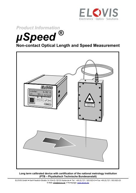
Electronics · Optics · SolutionsProduct InformationµSpeed ®Non-contact Optical Length and Speed MeasurementLong term calibrated device with certification of the national metrology institution(PTB – Physikalisch Technische Bundesanstalt)ELOVIS <strong>GmbH</strong> • Karl-Friedrich-Straße 14-18 • D–76133 Karlsruhe • Tel.: +49 (0) 721 / 933 823-0 • Fax +49 (0) 721 / 933 823-23E-Mail: Info@elovis.de • Homepage: www.elovis.de
ELOVIS GMBH - 01.04.2007µSpeed-product informationSafety and Laser ProtectionThis unit is a class IIIB laser product and complies with EN60825-1:2001.Complies with 21 CFR 1040.10 and 1040.11 except for deviations pursuant toLaser Notice No. 50, dated July 26, 2001.INVISIBLE LASER RADIATION -AVOID DIRECT EXPOSURETO BEAMINVISIBLE LASER RADIATIONWHEN OPENLASER CLASS 3BWAVELENGTH 780nmCW OUTPUT POWER 25mWEN 60825-1:2001The following safety features required tocomply with the Bureau of Radiological HealthClass IIB laser requirements are included:• Key-operated power switch on controller• Laser indicator light on controller and laser• Delayed laser startup-laser indicator light onprior to laser radiation• Laser beam blocking device• Interlock capability for remote shut-offTHE INSTRUCTION MANUAL MUST BE STUDIED CAREFULLY BEFOREINSTALLATION AND COMMISSIONING OF THE µSPEED SYSTEM. THE MEASURESAND RECOMMENDATIONS ARE TO BE FOLLOWED.page 2/22
ELOVIS GMBH - 01.04.2007µSpeed-product informationGeneral Description®The µSpeed <strong>Sensor</strong> is a LASER-DOPPLER-Velocimeter for non-contact speed and lengthmeasurement to be used for all kinds of material with micro structured surfaces. Its simpleuse and robust design makes it suitable for a variety of applications in all kinds of industries.Speed and length of material with a length more than 5m can be measured long term with anaccuracy, better than +/-0,05%. The laser-doppler principle allows precise measurement onmost technical surfaces. The unit’s compact design makes it also suited for confined spaces.There are versions available, for up to 60m/s [11800f/mn] and stand off distances between120mm [4,7in] and 500mm [19,6in]. In addition, application-specific modifications andhousing protections as well as cooling devices can be asked for.µSpeed is also available in a certified form with the certification of the national metrologyinstitution of Germany (PTB – Physikalisch Technische Bundesanstalt, Braunschweig).Measurement PrincipleUsing two laser beams a stripe pattern is projected onto the object. The intensity of thereflection is modulated by the movement of the object and detected by the sensor. Thefrequency of the intensity modulation is proportional to the velocity of the object and thus tothe doppler frequency. There is no need for markings or reference points on the object.ApplicationsSpeed and length measurement for metals, paper, timber, textiles, non-woven, plastics, rubber web material, tapes, pipes, sheets, film, wire, cable, goods in pieces cutting length, process control, positioning, dosing, production data acquisition speed measurement for process control purposeTechnical Specificationsspeed range 0m/min...3600m/min [0ft/mn…11800ft/mn] *1)typical accuracy 0,05% *2)stand off distance 120mm [4,7in] +/- 5mm (+/- 20mm) [0,12in (+/-0,7in)]depfh of field 240mm [9,4in] +/- 10mm (+/- 40mm) [0,24in (+/-1,5in)]500mm [19,6in] +/- 20mm (+/- 80mm) [0,36in (+/-3,1in)] *3)interfaces1x RS 232 unidirectional for printer1x RS 232 bidirectional for PCI²C Bus for external keyboard or special applicationsanalog output0...4 V (programmable)impulse output1 ... 10000 Impulses/m (programmable)optical isolated outputs stop contact, pre-stop contact, alarmLASER diode 25 mW / 780 nm (class 3b)power supply230V / 50-60 Hz , 110 V / 50-60 Hz*1) Valid for µSpeed-S1 to – S60*2) Valid for lengths more than 5m (1σ) / >10m (2σ) / >20m (3σ) see also figure on page 4*3) µSpeed adjustment at the extreme range of values in round brackets may reduce measurement accuracy► Specifications are subject to change without notice.page 3/22
ELOVIS GMBH - 01.04.2007µSpeed-product informationMounting LayoutWiring diagramm of the system220V/50HzSerielles serial cable Kabel (RS232)220V/50HzcontrolBedien-einheitunitµAWS-B-EµSpeed-Bsensor <strong>Sensor</strong>kabel cablesensorheadµSpeed-S<strong>Sensor</strong>kopfµAWS-S5-EPowerPrinterProtokolldruckerMounting tolerances of the standard systemFeeding direction Bewegungsrichtungmax ±1°90°±1°120±3 120mm mm ± 5mm µAWS-S5-E240mm ±10mm500mm ±20mmBFeeding ewegungsrichtung directionpage 4/22
ELOVIS GMBH - 01.04.2007µSpeed-product information<strong>Sensor</strong> <strong>Head</strong>Dimensioned sketch of the sensor headThe housing of the sensor head, which is made of aluminium, is closed with 6 screws. Theemission of the laser beam goes through a special glas.A ready made 3m five-pole cable for the connection of the sensor head and the processingunit is part of the scope of delivery. The voltage of the sensor head is 5VDC.A two-colour LED at the side of the plug shows the operation status of the laser. Red lightmeans off – Green light means laser on!3923,594 80LASERSTRAHLUNGNICHT DEM STRAHL AUSSETZENLASER KLASSE 3Bmeasuring pointMessvolumen32,518 78 138Bezugskanten reference corner154 120 (µAWS-S5)120 / 240 / 500240 (µAWS-S10)Befestigungslöcher Durchgangslöcher M5 unten Gewinde M6x12Direction for mounting:The scope of delivery includes also a PVC isolation plate (94x154x1mm) and 6 plasticscrews M6 x 12. The customer or integrator has to provide a vibration free mounting plate(appr. 4mm thick) with 6 holes according to the above shown hole pattern. Please considerthe mounting tolerances of the µSpeed system mentioned on page 5. Make sure that thesensor head is mounted in a isolated way by using the plastic screws as well as the isolationplate.page 5/22
ELOVIS GMBH - 01.04.2007µSpeed-product informationProcessing UnitDimensioned sketch of the processing unitThe housing of the processing unit is made of a aluminium frame with aluminium side walls.The unit is to be used both as table unit or for mounting into instrument panels. With thedelivered clamp devices the processingUnit can be fastened in a cut-out of 138 +1,0 x 92 +0,8 mm. Herefore the plastic feet have to beremoved.The front plate carries a foil keyboard including display and four operation keys as well as akey switch.9096Standard Schalttafelgehäuse DIN43700Frontplatte 144 x 96Schalttafelausschnitt 138 x 921381441784page 6/22
ELOVIS GMBH - 01.04.2007µSpeed-product informationFront ViewSTATUSNr. Description1 Key switch - is used to switch the LASER beam on/off2 LASER ON LED: Lighted if Laser is on.3 Left Button: This key is for menu selection or cipher input (left side)4 Right Button: This key is for menu selection or cipher input (right side)5 Return: Start / Stop function during measurement; Confirmation of selected menupoints or ciphers6 Escape: Change menu level; interruption of manual input7 Status LED: - indicates failure or stand still8 Display: 16 letters x 2 lines alphanumerical Displaypage 7/22
ELOVIS GMBH - 01.04.2007µSpeed-product informationRear ViewNr. Description1 9 Pin Sub-D plug for connection of the asynchronous serial RS232 interface (DTE)2 TTL I/O: Impulse output, direction output, DAC-output, Error/Hold.For the connection of the µSpeed-IMP-module3 Optoisolated I/O: 10 pole connection device with Input for Start, Direction, Interlockand output for Pre-Stop, Stop and Hold/Error.4 Main fuse: M400mA5 Power supply (230V/50Hz or 115V/50Hz)6 Main switch (Power ON/OFF)7 secondary fuse for the auxiliary voltage8 connector for the sensor head9 9-pin Sub-D-Plug for serial printerpage 8/22
ELOVIS GMBH - 01.04.2007µSpeed-product informationPin Connection LayoutDescription- [+7V] Output voltage is additionally fused with 125 mA. The output is only used for theeventual supply of the optocouppled inputs.- Interlock is used for the remote control of the laser (LASER ON/OFF). Hereby µSpeedcan be integrated in a safety circle around a machine or production line.- Direction is used for the change of the counting direction by external direction signal. It isrecommended to use the direction port at the µSpeed-IP-module.- Gate takes a mute signal of an external device, for temporary switching the sensor dumbwithout resetting the measured length. E.g. during the movement of defective material,which has to be cut out later. of a machine if the machine is at a rest. It is recommendedto use the port at the µSpeed-IP-module.- Start is used fort he external control of the measurement. A start signal results inresetting the unit.+7VOpto opto-isolated isolierte I/Ofuse 125 mASicherung 125mAf2k22k22k22k212345678910GND+7V+Interlock+Direction+Start+Gate+Stop+Vorkontak+ Pre-Contact t+Hold/Error-CommonInputs:max50V/20mAOutputs : max 50V / 100mAPin Nr. Description1 GND: (Internal 0-Volt)2 +7V (fuse 125mA)3 Interlock + Input (min. 2mA/5V, max. 20mA/50V)4 Direction + Input (min. 2mA/5V, max. 20mA/50V)5 Start + Input (min. 2mA/5V, max. 20mA/50V)6 Gate + Input (min. 2mA/5V, max. 20mA/50V)7 Stop + Output / End-contact (max 100mA, 300V )8 Pre-Stop + Output / precontact (max 100mA, 300V )9 Hold/Error + Output (max 100mA, 300V )10 Commonpage 9/22
ELOVIS GMBH - 01.04.2007µSpeed-product informationµSpeed AccessoriesµSpeed-TUBEµSpeed-CMSµSpeed-RCSµSpeed-IMPµSpeed-KEYµSpeed-LMµSpeed-PµSpeed-IMPWµSpeed-DISPµSpeed-HSEµSpeed-TRI<strong>Sensor</strong> <strong>Head</strong> TubeConfiguration & MonitoringSoftwareRemote Control &Production Data Acquisition SoftwareImpulse Processing ModuleComfort KeyboardLong-term MemoryPrinterIMP WheelAdditional DisplayProtective Housing<strong>Sensor</strong> Tripodpage 10/22
ELOVIS GMBH – 01.04.2007µSpeed-product information<strong>Sensor</strong> <strong>Head</strong> TubeµSpeed-TUBEDescriptionThe <strong>Sensor</strong> <strong>Head</strong> Tube reduces the dangerof looking directly into the laser beam.The standard tube reduces the gap betweensensor head and material surface to 10mmonly. In connection with other protectionactivities (light trap, mechanical shutter,manipulation prevention, machine safetyenclosure with emergency stop switch) thelaser class of the system can be reduced toclass 1. Hereby further activities as e.g. theneed of an employer who is in charge of laserprotection, is not necessary any more.FeaturesHeigth:Width:Material:110 mm20 x 30 mmAluminiumpage 11/22
ELOVIS GMBH – 01.04.2007µSpeed-product informationConfiguration & Monitoring SoftwareµSpeed-CMSDescriptionThe configuration- and monitoring software isinstalled on a PC or a laptop. By connectingthe µSpeed via RS 232 to the laptop, thelaptop can be used for monitoring themeasurement process or for showing orchanging the configuration of the µSpeedsystem.All measurement values can be displayed ingraphical way.The software enables the user additionally tomemorize to the PC all data or measurementvalues which were monitored during theconnection of µSpeed and PC.FeaturesNumber of files:Interpretation:Transmission format:unlimitedserial, RS232binary, ASCIIpage 12/22
ELOVIS GMBH – 01.04.2007µSpeed-product informationRemote Control &Production Data Acquisition SoftwareµSpeed-RCSDescriptionThe software module µSpeed-RCS enablesthe user to read µSpeed data by a PLC(SPS) or a PPC (PPS) system or any othersuperior host computer at any time, definedby the host. Additionally the host computercan send data to µSpeed. All functions ofµSpeed, which are available by pressingµSpeed keys can then be operated remotecontrolled by the host. The module uses theintegrated RS-232 interface forcommunication.µSpeed-RCS provides/enables:EigenschaftenInterpretation:Transmission format:serial, RS232binary, ASCII• To read µSpeed data by PLC (SPS)or PPC (PPS) or any other hostcomputer at any time defined by thehost.• The integration of µSpeed into thedata processing of the production.• To give the possibility to install auser specific visualization (e.b. byVisual Basic).• To control the µSpeed by externalcomputer or host systems.The functions of the RCS module can beclassified as follows:• Replacement of the sensor keys• To request measurement values• To set parameterspage 13/22
ELOVIS GMBH – 01.04.2007µSpeed-product informationImpulse Processing µSpeed-IMP certified by national metrology institution PTB applied for patentby a external encoder (contact wheel plusencoder that in most cases is alreadymounted to the machine). Hereby µSpeed-IMPdetects the direction as well as start and stopof the material movement (not machinemovement). In addition speed below themeasurement limit of µSpeed is measured byµSpeed-IMP. As the external encoder isgetting continuously calibrated by µSpeed, dayto day use problems as well as material andthickness changes won’t affect themeasurement. By using this configuration thecomplete measurement system is long termstable and long term calibrated.DescriptionµSpeed-IMP provides four functions:a.) direction recognitionb.) start and stop detectionc.) low speed measurementd.) pulse outputBy the use of µSpeed-IMP the signals of anexternal pulse generator device areprocessed to achieve the functions a, b andc. The pulse generator device can be either aencoder, which is driven by contact wheel orby transporting cylinder, or directly by aelectric drive. The pulse output function (d)operates without any other external deviceand enables µSpeed to send quadraturepulse signals to replace contact tachometers.µSpeed-IMP is certified by the nationalmetrology institution PTB (Germany) and hasbeen applied for patent.For achieving the function a, b and c, twoshifted by 90° pulse input signals arenecessary, which in general will be providedConnectionThe fast and easy connection with µSpeed-IMP is done by plugging in the included indelivery 9-pole Sub-D cable in the µSpeed TTLI/O. The external encoder has to be connectedto the corresponding clamp (channel A,channel B) of the µSpeed-IMP. See Figure 1.The pulse output signals are at clamp 9, 10, 13and 14. µSpeed-IMP is designed to bemounted by top hat rail. Similarly the µSpeed-IMP has to be connected to the power supply(carried out by 24V auxiliary supply). TheGrounding of the external encoder has to bethe same as for the IMP unit (important: similarreference ground).12345678910111213141516InputInput------OutputOutputOutputSupplyOutputOutputOutputSupplyVISIONETImpulse-Processing µSpeed-IMPImpulse AImpulse Bn.c.n.c.n.c.n.c.n.c.n.c.Channel /AChannel /BImpulse /N24VChannel AChannel BImpulse N0VTable 1: Connector pin assignmentpage 14/22
ELOVIS GMBH – 01.04.2007µSpeed-product informationEncoderA, BImpulse123424V=Spur A5678Spur BSpur /BSpur /ASpur ASpur BPower ImpGate TTL I/O Dir9 10 11 1213 14 15 16µAWSTTL I/O24V=MasseSpur /ASpur /BFigure 4: Timing diagram quadrature pulseoutputFeatures & TranslationFigure 1: Connector pin assignment schemaSpur ASpur BSpur /ASpur /B1,5kΩFigure 2: Input circuit2,7kΩ24V0VChannel (Spur)Ground (Masse)Supply (Versorgung)........ 8-24V=µSpeed (µAWS)………… <strong>Sensor</strong> systemPower consumption......... max. 2WInputs…........................... Imp. AImp. BTTL I/OInput resistance…….........10kΩoptional 10kΩPullup resistanceInput - Hi.......................... 3-24VInput - Lo.........................
ELOVIS GMBH – 01.04.2007µSpeed-product informationComfort KeyboardµSpeed-KEY7PQRS8TUV9WXYZAs e.g. in mobile phones, most keys are usedfor multiple input. Therefore text or parametercan easily and fast be changed.4GHI5JKL6MNOThe selection for multiple input of one key isdone by pressing the same key several timesin a fast way. The respectively selected valueis shown in the display.1a ↔A0.__.2ABC3DEF• ±The µSpeed processing unit identifies byitself that the µSpeed-KEY has been pluggedin, and makes the connection and switchesthe operation itself to µSpeed-KEY. The fourkeys of the processing unit have the samefunctionality as the according keys of thecomfort keyboard.DescriptionThe comfort keyboard µSpeed-KEY makesdata input to the µSpeed unit more easy. Thecomfort keyboard makes sense, if data inputhas to be done frequently and manually by anoperator – e.g. for typing in length values forcut-to-length applications such as pre lengthand end length.Beside the two ARROW keys, RETURN- andESCAPE-key, 12 keys for typing in numbersand letters are integrated into µSpeed-KEY.The comfort keyboard is designated to beinstalled into a front panel. The connection ofthe comfort keyboard is done by a 9-polecable (I²C-Bus) to the TTL I/O-interface of theµSpeed processing unit.FeaturesInterfaceDimensions (BxH)FrontI²C-Bus96 x 96 mmmembranekeyboard4 x 4 Keyspage 16/22
ELOVIS GMBH – 01.04.2007µSpeed-product informationLong-term MemoryµSpeed-LMsystem. The data selection can be done bychoosing the memory file number or thememorization date of the data file.The µSpeed-LM long-term memory is a flash-EEPROM with a capacity of more than 50000data files.DescriptionThe µSpeed-LM long-term memory electronicboard (ring memory) is designed to beintegrated into the µSpeed processing unitand is used for memorization of up to 50.000measurement values. The Measurementvalues can be read out via serialinterface.and by laptop, PC or any superiorhost computer.One data file memorizes not only themeasurement value “Length” itself, but alsothe running memory file number, the date andhour of the measurement, the user name aswell as the failure flag which tells about thevalidity of the measurement value.Additionally a shift performance counter isimplemented into µSpeed-LM, whichmemorizes the performance of up to 6working shifts. By this counter, the productionvolume and the total lengths of each shift canbe memorized and then analyzed by aproduction data analyze software.The memorized data can be selected andisplayed by the operator menu of theµSpeed processing unit and then be sent byserial interface to an external computingµSpeed-LM memorizes the data in a cyclicalway, that means that if the memory capazityhas been reached, the oldes data file will beover written by the newest data file and soon. The running file number will count on andon. By the high memory capacity thememorized data files can rest long time in thememory until they will be over written.It is not possible to delete data files manually(not by accident – and not if wanted!).FeaturesFile capacity……………......... appr. 50.000Data file format....1. Running file number2. Failure flag of the measurement value(correct measurement)3. Date/Hour of measurement4. User 15. User 26. Failure flag of data file(correct memorization)Data reading and analyze: serial, RS232page 17/22
ELOVIS GMBH – 01.04.2007µSpeed-product informationPrinterµSpeed-PThe operator can select each of this signalsources by menu of the processing unit tocombine them with one of the two formatstrings. Therefore the print out can becontrolled very flexible.Besides logos and texts which can beprogramed in a fix way, the following runningprogram parameter can be read out:DescriptionThe EPSON TM-U295 printer enables theuser to print out measurement values oroptionally (by additional ordering) customerspecific production data inclusive customerlogos into document forms.The format of the print out is defined by twoindependent format strings which arememorized in the processing unit.The print out of the last measurement resultstarts by receiving the start signal which isgiven to start a new measurement.Five different ways of giving the start signalcan be used:1. RETURN-Key of the processing unit2. RIGHT ARROW Key3. LEFT ARROW Key4. External start signal input5. Printer busy (by inserting paper intothe printer)1. User 12. User 23. Date4. Hour5. Running number of measurement6. Failure flag of the measurement7. Formated length measurement valueThe printer is connected to the RS232 printout port of the µSpeed processing unit.FeaturesPrinting method............... 7-Pin-Matrix-Shuttle-PrinterSize of Paper (WxH)....... 80x69 - 1582x257Characters per Inch......... 13,5 / 16,2Printing speed………....... 2,1 LPSLife time of cartridge….... 15 Mio. CharactersInterface…...................... RS-232Buffer............................... 512 or 35 BytesWeight............................. 1,6 kgPrinter size (WxDxH)…... 180x190,5x101,5Supply……....................... 24 V=(all size units in mm – if nothing elsementioned)Remark: Also other RS232 printers are available!IMP-WHEELµSpeed-IMPWpage 18/22
ELOVIS GMBH – 01.04.2007µSpeed-Product informationIn combination with the µSpeed-IMP, the IMPwheel can be used to send direction and gatesignals to µSpeed. The µSpeed IMP Wheelenables also to measure extremely low speedwhich in general can not be measured by anylaser-doppler system.In combination with µSpeed-IMP and µSpeedbasic unit, the µSpeed-IMP wheel is certifiedby the national metrology institution PTB(Germany).DescriptionTo recognize the direction of the materialmovement as well as for measurement oflowest speed (e.g. 5mm/hour), µSpeed-IMPWconsists of- rubber nib roll with 500mm circumference- encoder, 10-30VDC, 500imp/turn, push-pulloutput or contra pulse (alternative: 5VDC,TTL)- arm with springpage 19/22µSpeed-Options
ELOVIS GMBH – 01.04.2007µSpeed-Product informationAdditional DisplayµSpeed-DISPpicture shows 4-spaces 7-segment displayDescriptionµSpeed can additionally be equipped with aalphanumeric size display, which enables theuser to read measurement values and statusmessages over distances of more than 10 m.µSpeed-DISP in standard configuration is a8-spaces 7-segment display. µSpeed-DISPcan optionally be ordered as a two linedisplay with each 16-spaces 7-segments.The display scope of delivery includes amounting plate and connection cable.Other sizes of displays and more than one ortwo arrays due to customer specifications,are possible. Please contact us!page 20/22µSpeed-Options
ELOVIS GMBH – 01.04.2007µSpeed-Product informationProtective housingµSpeed-HSEStandard Protective Housing µSpeed-HSEProtective housing with shild µSpeed-HSEaDescriptionThe µSpeed-HSE protective housing is usedto protect the sensor head against pollutionand high temperature.The housing is standardly delivered with a 5moilresistand flexible tube for air conditioning.The air with a max. temperature of 30°C hasto be delivered by the customer.By the continuous flowing air, the sensor isalso protected against pollution, fog orhumidity which could affect the measurementability of the sensor.The housing can optionally be equipped witha protection shild (µSpeed-HSEa – seepicture below) or with a laser protection tube.According to the temperature of the incomingair, the housing can be used in surroundingswith 80°C and more.page 21/22µSpeed-Options
ELOVIS GMBH – 01.04.2007µSpeed-Product information<strong>Sensor</strong>-TripodµAWS-TRITripod µAWS-TRI with standard sensor headTripod µAWS-TRI with conter weight incombination with housing µAWS-HSEDescriptionAufgrund der geringen Baugröße sowie demäußerst geringen Gewicht des <strong>Sensor</strong>kopfes(1kg) kann der <strong>Sensor</strong> auch portabel eingesetztwerden.Das <strong>Sensor</strong>kopf-Stativ µAWS-TRI dienthierbei als Standardhalterung. MittelsGalgenausleger und Kugelkopf ist dasSystem nahezu an jeder Stelle einerProduktions- oder Umwickelmaschine innerhalbkurzer Zeit stabil aufgebaut undmessbereit ausgerichtet. Durch denGalgenausleger kann der <strong>Sensor</strong>kopf bis zu2,5m entfernt vom Zentrum des Stativsjustiert werden.Durch die stabile Bauweise des Stativs ist essogar möglich das <strong>Sensor</strong> UmgehäuseµAWS-HSE für portablen Aufbau zuverwenden. Für diesen Anwendungsfallkommt das standardmäßig gelieferteGegengewicht (orange) zum Einsatz.Wichtig bei der portablen Nutzung des<strong>Sensor</strong>s ist die Kenntnis und Berücksichtigungder ELOVIS Laserschutzvorschriften.Die Nutzer von portablen <strong>Sensor</strong>enmüssen dementsprechend besonders inSachen Laserschutz geschult und ausgebildetwerden.page 22/22µSpeed-Options