Chapter27
Chapter27
Chapter27

Create successful ePaper yourself
Turn your PDF publications into a flip-book with our unique Google optimized e-Paper software.
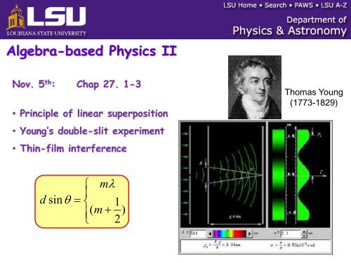
Algebra-based Physics IINov. 5 th : Chap 27. 1-3• Principle of linear superposition• Young’s double-slit experiment• Thin-film interferenceThomas Young(1773-1829)d⎧ mλ⎪sinθ= ⎨ 1⎪( m + )⎩ 2
Ch. 27. Interference and the Wave Nature of LightUp to now, we have been studying geometrical optics, where the wavelengthof the light is much smaller than the size of our mirrors and lenses and thedistances between them.→ The propagation of light is well described by linear rays except whenreflected or refracted at the surface of materials.Now we will study wave optics, where the wavelength of the light iscomparable to the size of an obstacle or aperture in its path.→ This leads to the wave phenomena of light called interference anddiffraction.
27.1 The Principle of Linear SuperpositionTake two waves of equalamplitude and wavelength andhave them meet at a commonpoint:If the two waves are in-phase,then they meet crest-to-crestand trough-to-trough.Their two amplitudes add to each other. In this case, the resulting wave wouldhave an amplitude that doubled.This is called Constructive Interference (CI).Define Optical Path Difference (OPD):OPD = The difference in distance that two waves travel.For CI to occur, we need the waves to meet crest-to-crest, thus the wavesmust differ by an integer multiple of the wavelength λ:OPD = mλ,m = 0,1, 2, ... Constructive Interference
This is called Destructive Interference (DI).Now take two waves of equalamplitude and wavelength and havethem meet at a common point, butthis time have them be out-of-phase.Thus, they now meet crest-totrough.The resulting wave has zeroamplitude. The two wavescancel out.For DI to occur, we need the waves to meet crest-to-trough, thus the wavesmust differ by any odd integer number of ½λ :OPD = (m + 1 2)λ,m = 0,1, 2, ... Destructive InterferenceAll waves do this, including EM waves, and since light is an EM wave, lightwaves do this too.
For interference to continue at some point, the two sources of light producingthe waves must be coherent, which means that their phase relationship relativeto each other remains constant in time.27.2 Young’s Double Slit Experiment (http://www.youtube.com/watch?v=AMBcgVlamoU)Look what happens when water waves strike a barrier with two slits cut in it:Each slit acts like a coherent point source of waves.The waves diverge from each slit and interfere with each other.The bright regions are areas of constructive interference, and the darkregions are areas of destructive interference.
In 1801 an English scientist Thomas Young repeated the double slit experiment,but this time with light.S 1S 2Coherent light sourceΔlPEach slit acts like a coherent lightsource.The two waves meet at point P ona screen.Δl is the optical path difference ofthe two light waves coming fromS 1 and S 2 .The two waves interfere with eachother, and if:Δl = mλConstructive interference, and wesee a bright spot.ScreenΔl=( m + 1)λ2Destructive interference,and we see a dark spot.Thus, we should see alternating bright and dark regions (called fringes) as wemove along the screen and the above two conditions are satisfied.Can we find a relationship between the fringes and the wavelength of the light?The answer is yes……………
PAssume the screen is far away from theslits which are small. This is called theFraunhofer approximation.S 1θThus, since the slits are very closetogether, θ is the same for each ray.dS 2θΔlθFrom the figure we see that:sinθ=Δld⇒ Δl = d sinθScreenWe know that for constructive interference:Thus,d sinθ=mλd sinθ = ( m + 12)λΔl = mλfor constructive interference.and...for destructive interference.These are the interference conditions for the double slit.m is the order ofthe fringe.
Brightm = 3m = 2m = 1m = 0m = 1m = 2m = 3Darkm = 3m = 2m = 1m = 0m = 0m = 1m = 2m = 3This is what a typical doubleslit interference patternwould look like.Notice there are alternatinglight and dark fringes.Also note that the centralfringe at θ = 0 is a brightfringe.It is also the brightest of thebright fringes.The order of the bright fringes starts at the central bright fringe.The order of the dark fringes starts right above and below the centralbright fringe.So, the second dark fringe on either side of the central bright fringe is the1 st order dark fringe, or m = 1.Remember, order means m.Young’s experiment provided strong evidence for the wave nature of light.If it was completely particle like, then we would only get two fringes on the screen, not aninterference pattern!
ExampleIn a Young’s double-slit experiment, the angle that locates the 3 rd darkfringe on either side of the central bright maximum is 2.5 o . The slits have aseparation distance d = 3.8 × 10 -5 m. What is the wavelength of the light?DarkWhat is the order?m = 2It is the 2 nd order dark fringe,m = 1or m = 2.2.5 o m = 0Since it’s a dark fringe, we know it must bedestructive interference:d sinθ = ( m + 12)λλ= d sin θm +12⇒ λ =−5(3.8×10 )(sin 2.52 +12o)⇒ λ =6.63×10⁻⁷m=663 nm
Algebra-based Physics IINov. 7 th : Chap 27. 3-5• Thin-film interference• DiffractionReflection pattern from a soap filmAnnouncements:• HW9 is posted• 3 rd -exam: Nov. 15 -17Reflection pattern from a CD
Double slit interferencedS 1S 2θΔlθθPYd⎧mλConstructive⎪sinθ= ⎨ 1⎪ ( m + ) Destructive⎩ 2LScreen⎧ mλ⎪L bright⎪ dY = Ltanθ≈ Lsinθ=⎨ 1⎪ ( m + ) λL 2⎪dark⎩ d
Clicker Question 27 - 1In our discussion of Young’s double slit experiment, we only consideredmonochromatic light (light of one color). What would the interferencepattern on the screen look like if we used white light instead?1. It would look the same.2. We would see coloredfringes.3. There would be nofringes.99%1% 0%It would look ...We would see c...There would be...
27.3 Thin Film InterferenceLight waves can interfere in many situations. All we need is a difference in opticalpath length.As an example, let’s consider a thin film of oil or gasoline floating on the surfaceof water:Part of a light ray gets reflected (1) from thesurface of the film, and part gets refracted (2).Then the refracted ray reflects back off thefilm/water interface and heads back into theair toward our eye.Thus, two rays reach our eyes, and ray 2 hastraveled farther than ray 1. Thus, there is adifference in the optical path length.If the film is thin, and the ray strikes almostperpendicularly to the film, then the OPD isjust twice the film thickness, or Δl = 2t.If 2t = mλ , we have ConstructiveInterference and the film appears bright.22t = ( m + 1 )λIf, we have DestructiveInterference and the film appears dark.
The optical path difference occurs inside the film, so the index of refraction thatis important here is n film .What is the wavelength of the light in the film (λ film )?nfilm=cvfilm=cf⋅vffilm=λλvacfilmλ =filmλnvacfilmOne more important point:When waves reflect from a boundary, it is possible for them to change their phase.1. Light rays will get phase shifted by ½λ uponreflection when they are traveling from a smallerindex of refraction to a larger index of refraction.Smaller n → larger n → Phase shift!2. Light rays will experience no phase shift uponreflection when they are traveling from a larger indexof refraction to a smaller index of refraction.Larger n → smaller n → No phase shift!
So a phase shift can occur upon reflection.For thin films then the following is used:Δl+ (any phase shifts) =Interference condition2t+(phase shifts)=⎧⎨⎩mλ,( m + )1λ2,Film appears brightFilm appears dark
ExampleA soap film (n = 1.33) is 375 nm thick and is surrounded on both sidesby air. Sunlight, whose wavelengths (in vacuum) extend from 380 nmto 750 nm strikes the film nearly perpendicularly. For whichwavelength(s) in this range does the film look bright in reflected light?sunlightR 1R 21 2airn = 1.00soapn = 1.33n = 1.00airtWe want the film to appear bright,which means constructive interference:Δl + (phase shifts) = mλDo we have any phase shifts?At R 1 we are going from a smaller n toa larger n → ½λ phase shift.At R 2 we are going from a larger n to asmaller n → No phase shift.So now we have 1 phase shift:12t + 2λ = mλ⇒ t = ( m + 1 ) λ22This λ is the λ film :λfilm2t= m +12But λ =vacnfilmλfilm⇒λ vac=n film2tm +12
⇒λ vac=(2)(375 nm)(1.33)m +12=997.5 nmm +12m0123λ vac1995 nm665 nm399 nm285 nmThese two are in the visiblespectrum (red and violet).Thus, the film appears redish/violet.
Algebra-based Physics IINov. 10 th : Chap 27. 5-7• Diffraction• Resolving power• The diffraction gratingHole diffractionAnnouncements:• HW10 for Chap. 27 is posted• 3 rd -exam: Nov. 15 -17Halogen light diffraction
27.5 DiffractionDiffraction is the bending of waves around obstacles or around the edges ofopenings.It is an interference effect – explained by Dutch scientist Christian Huygens.Huygens Principle:Every point on a wave front acts as a tiny source of wavelets that move forwardwith the same speed as the wave. At a later time, the new wave front is thesurface that is tangent to the wavelets.As an example, consider sound waves diffracting thru an opening.
Divide the opening up into equally spaced points,here we’ve chosen 5.Each of these points acts like a source of waves orwavelets.The wave front is always tangent to the waves.The direction of propagation of the wave is alwaysperpendicular to the wave front.Thus, the wave can bend (or diffract) thru anopening or around a corner.So what determines the degree of the diffractivebending?It is determined by the ratio of the wavelength ofthe wave to the size (width) of the opening orobstacle.DiffractionThus, for more diffraction (or bending) of the waves, we want longer wavelengthsand smaller openings.≈λW
We get more diffraction for the situation on theright, where the ratio λ/W is larger.
Single-slit DiffractionConsider monochromatic light of wavelength λ passing thru a single, narrowslit of width W.If no diffraction occurred, we wouldjust see one bright fringe directlybehind the slit.But, due to diffraction effects, we seean interference pattern – alternatingbright and dark fringes.As in the case for the double slit, heretoo do we have a central brightmaximum. Why?Huygens: Wavelets arriving at the centerof the screen are traveling parallel andessentially the same distance. Since theOPD is zero, they arrive in phase andinterfere constructively.
But, farther up the screen from the central bright maximum, the OPD betweenHuygen sources is not zero.Here, for example, wavelets from sources 1 and2 are out of phase and would interferedestructively on the screen, which is located afar distance away.From the figure, we see that:sinθ =mλWWidthThis is the condition for dark fringes for singleslitdiffraction, with m = 1, 2, 3,…
27.6 Resolving PowerResolving Power: The ability of an optical instrument to distinguish (or resolve)two closely-spaced objects.Look at the headlights of a car as it backs away from you to a far distance:When the car is close, it is easy to distinguish two separate headlights.But as it gets farther away, it’s harder to resolve the two headlights.Finally, there is a certain point when the car gets even farther away, that wecan’t distinguish the two headlights clearly.This inability to resolve two closely-spaced objects is due to diffraction.
We have light passing thru openings, i.e. my eyes, a telescope, a microscope –any optical instrument – and it’s diffraction thru these apertures that limits myresolution.The screen to the left shows the diffractionpattern for light from one object passing thrua small circular opening. Notice there is acentral bright fringe and alternating brightand dark fringes.θ locates the angle from the central brightfringe to the first dark fringe.If the screen distance is much larger than thewidth of the circular aperture (D), then:1.22λsin θ =D
Now, if we have two objects, we would get the following:Each object creates a diffractionpattern on the screen.I can distinguish the two objectsnow, since their diffraction patternsare widely separated.But look what happens if I movethem closer together:apertureObject 1 Object 2Now their diffraction patternsoverlap, and I am unable todistinguish two separate objects.It is useful to have a criterion for judging whether or not two objects areresolved.We use the Rayleigh Criterion for Resolution: We say that two closely-spacedobjects are just resolved when the first dark fringe of one image falls on thecentral bright fringe of the other.
Here is an image of two objects that are justresolved.Notice, the first dark fringe of one image is right atthe edge of the central bright fringe of the other.This sets a condition on the minimum anglebetween the two objects being resolved.Thus, if θ < θ min , then we won’t be able to resolvethe two objects.Since θ min is small, then sinθ≈ θ .minminThus, the Rayleigh Criterion for Resolutionbecomes:θ ≈1. min22λD
ExampleYou are looking down at earth from inside a jetliner flying at an altitude of8690 m. The pupil of your eye has a diameter of 2.00 mm. Determine howfar apart two cars must be on the ground if you are to have any hope ofdistinguishing between them in red light (wavelength = 665 nm in vacuum).Take into account the index of refraction in the eye.Solution:eyes = rθ Since r >> D.2.00 mmθmin ≈1.22λD=srs1.22λr=Drθrs1.22λ eyerDλλ =vaceye= neyecar 1 car 2Ss1.22λ=Dnvaceyers =−91.22(665×10 )(8690)(0.002)(1.36)=2.59 m
27.7 The Diffraction GratingWe see diffraction patterns of alternating bright and dark fringes whenmonochromatic light is shined on a single or double slit.What if we shined light on many close-spaced slits? What would weexpect to see?Such an instrument is called a Diffraction Grating.Some of them can have tens of thousands of slits per cm.Again we see alternating bright and dark fringes:Each slit acts as asource of wavelets inaccord with Huygens.The figure to the leftshows have the first andsecond order (m = 1 and2) maxima (brightfringes) develop.
Fringe formation of multiple diffractionThe envelop of singleslit diffractionThe results of multislitinterferencePrinciple maxima
diffraction pattern of a grating
27.9 X-ray DiffractionNot all diffraction gratings are artificially made. Some are made by MotherNature.Take table salt, for example, NaCl.ClNaThe Na and Cl ions form a 3-dimensionalperiodic array of atoms called a crystal.The distance between the atoms (interatomicspacing) is about 1 Ǻ (1 × 10 -10 m).Thus, this distance could act like the slitseparation distance on a diffraction grating forwaves with an appropriate wavelength.Thus, let’s choose light whosewavelength is ~ 1 × 10 -10 m.Light of this wavelength resides inthe X-ray part of the EM spectrum.By shining X-rays on the crystal, weshould see diffraction effects.
Indeed, a diffraction pattern does result when you shine X-rays on acrystalline material.Cubic NaClDNA Double HelixThe diffraction pattern gives us information about the structure of thecrystal and the distance between its atoms.X-ray diffraction is also vitally important to determining the structures ofbiological molecules, like proteins.
Sr 2 RuO 44 μ m 4 μm2 μ2 μ mm0 μmSTMLEED