Experiment 1: Introduction to Ray Optics - Andrewgloag.com
Experiment 1: Introduction to Ray Optics - Andrewgloag.com
Experiment 1: Introduction to Ray Optics - Andrewgloag.com
- No tags were found...

You also want an ePaper? Increase the reach of your titles
YUMPU automatically turns print PDFs into web optimized ePapers that Google loves.
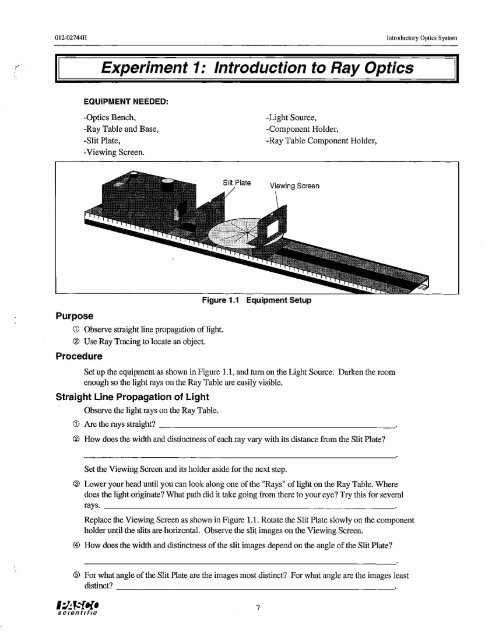
012~02744H Introduc<strong>to</strong>ry <strong>Optics</strong> Systeml'<strong>Experiment</strong> 1: <strong>Introduction</strong> <strong>to</strong> <strong>Ray</strong> <strong>Optics</strong>EQUIPMENT NEEDED:-<strong>Optics</strong> Bench,-<strong>Ray</strong> Table and Base,-Slit Plate,-Viewing Screen.-Light Source,-Component Holder,-<strong>Ray</strong> Table Component Holder,Slit PlatePurposeFigure 1.1(j) Observe straight line propagation of light.® Use <strong>Ray</strong> Tracing <strong>to</strong> locate an object.ProcedureEquipment SetupSet up the equipment as shown in Figure 1.1, and tum on the Light Source. Darken the roomenough so the light rays on the <strong>Ray</strong> Table are easily visible.Straight Line Propagation of LightObserve the light rays on the <strong>Ray</strong> Table.(j) Are the rays straight?® How does the width and distinctness ofeach ray vary with its distance from the Slit Plate?'Set the Viewing Screen and its holder aside for the next step.® Lower your head until you can look along one ofthe "<strong>Ray</strong>s" oflight on the <strong>Ray</strong> Table. Wheredoes the light originate? What path did it take going from there <strong>to</strong> your eye? Try this for severalrays._Replace the Viewing Screen as shown in Figure 1.1. Rotate the Slit Plate slowly on the <strong>com</strong>ponentholder until the slits are horizontal. Observe the slit images on the Viewing Screen.@How does the width and distinctness ofthe slit images depend on the angle ofthe Slit Plate?@ For what angle ofthe Slit Plate are the images most distinct? For what angle are the images leastdistinct?_,:1.:.f,."fI{.SCIentIfIc7
Introduc<strong>to</strong>ry <strong>Optics</strong> System012-02744H® On a separate sheet of paper, explain your observations in terms ofthe straight line propagationof light. Include a diagram showing how the width of the slit images depends on theorientation of the Light Bulb filament with respect <strong>to</strong> the Slit Plate._<strong>Ray</strong> Tracing: Locating the FilamentFilamentComponentHolderSlit Plate<strong>Ray</strong>s on <strong>Ray</strong>TableNole: The vertical edge of the notchon the side of the Light Sourceindicates the position of the filament.CenterPapereDFigure 1.2: <strong>Ray</strong> TracingYou can use the fact that light propagates in a straight line <strong>to</strong> measure the distance betweenthe Light Source filament and the center of the <strong>Ray</strong> Table. Figure 1.2 shows how. The rayson the <strong>Ray</strong> Table all originate from the filament of the Light Source. Since light travels in astraight line, you need only extend the rays backward <strong>to</strong> locate the filament. (See Step 3 inthe first part of this experiment.)Place a piece of blank white paper on <strong>to</strong>p of the <strong>Ray</strong> Table, holding it there with a piece oftape. Make a reference mark on the paper at the position of the center of the <strong>Ray</strong> Table.Using a pencil and straight edge, trace the edges of several of the rays on<strong>to</strong> the paper.Remove the paper. Use the pencil and straightedge <strong>to</strong> extend each of the rays. Trace themback <strong>to</strong> their <strong>com</strong>mon point of intersection. (You may need <strong>to</strong> tape on an additional sheet ofpaper.) Label the filament and the center of the <strong>Ray</strong> Table on your diagram.Measure the distance between your reference mark and the point of intersection of the rays.® Use the metric scale on the <strong>Optics</strong> Bench <strong>to</strong> measure the distance between the filament andthe center of the <strong>Ray</strong> Table directly (see the note in Figure 1.2)._® How well do your measurements in Steps I and 2 agree? Comment. _One of the key ideas that this experiment illustrates is the ability for us <strong>to</strong> trace light rays <strong>to</strong>their origin or apparent origin. This concept will prove most useful in future experiments.8 I:l.:J:{Il'SCIentifIc
, <strong>Experiment</strong> 2: The Law of Reflection012-02744H Introduc<strong>to</strong>ry <strong>Optics</strong> SystemEQUIPMENT NEEDED:-<strong>Optics</strong> Bench-<strong>Ray</strong> Table and Base-Slit Plate-<strong>Ray</strong> <strong>Optics</strong> Mirror.-Light Source-Component Holder-Slit MaskSlit MaskSlit PlateFigure 2.1Equipment Setup<strong>Introduction</strong>The shape and location of the image created byreflection from a mirror of any shape is determinedby just a few simple principles. One oftheseprinciples you already know: light propagates in astraight line. You will have an opportunity <strong>to</strong> learnthe remaining principles in this experiment.To determine the basic principles underlying anyphenomenon, it is best <strong>to</strong> observe that phenomenonin its simplest possible form. In this experiment,you will observe the reflection ofa single ray oflight from a plane mirror. The principles youdiscover will be applied, inJater experiments, <strong>to</strong>more <strong>com</strong>plicated examples ofreflection.Angle ofReflectionAngle ofIncidenceFigure 2.2Incident and Reflected <strong>Ray</strong>s• \':I.:.~"fl{,sc/ent/flc9
Introduc<strong>to</strong>ry <strong>Optics</strong> SystemO!2-02744HProcedureCDSet up the equipment as shown in Figure 2.1. Adjust the <strong>com</strong>ponents so a single ray oflightis aligned with the bold anow labeled "Normal" on the <strong>Ray</strong> Table Degree Scale. Carefullyalign the flat reflecting surface of the mhTor with the bold line labeled "Component" on the<strong>Ray</strong> Table. With the mirror properly aligned, the bold anow on the <strong>Ray</strong> Table is normal (atright angles) <strong>to</strong> the plane of the reflecting surface.Rotate the <strong>Ray</strong> Table and observe the light ray. The angles ofincidence and reflection aremeasured with respect <strong>to</strong> the normal <strong>to</strong> the reflecting surface, as shown in Figure 2.2.By rotating the <strong>Ray</strong> Table, set the angle ofincidence <strong>to</strong> each of the settings shown in Table2.1. For each angle ofincidence, record the angle of reflection (Reflectionj). Repeat yourmeasurements with the incident ray <strong>com</strong>ing from the opposite side of the normal (Reflection,).Are the results for the two trials the same? Ifnot, <strong>to</strong> what do you attribute the differences?@ Part of the law of reflection states that the incident ray, the normal and the reflected ray all liein the same plane. Discuss how this is shown in your experiment_® What relationship holds between the angle ofincidence and the angle of reflection? _Additional QuestionsCDThe Law ofReflection has two parts. State bothpatts.@ You were asked <strong>to</strong> measure the angle of reflectionwhen the ray was incident on either side ofthenormal <strong>to</strong> the smface of the min'Of. What advantagesdoes this provide?® Physicists expend a great deal of energy in attempts<strong>to</strong> increase the accuracy with which an exact lawcan be proven valid. How might you test the LawofReflection <strong>to</strong> a higher level ofaccuracy than inthe experiment you just performed?Table 2.1 DataAngle of' Incidence Reflection!0'10'20'30'40'50'60'70'80'90'Reflection z10
012-D2744HIntroduc<strong>to</strong>ry <strong>Optics</strong> System( <strong>Experiment</strong> 3: Image Formation in a Plane MirrorEQUIPMENT NEEDED:-<strong>Optics</strong> Bench-<strong>Ray</strong> Table and Base-Slit Plate-Light Source-Component Holder-<strong>Ray</strong> <strong>Optics</strong> Mirror<strong>Introduction</strong>ProcedureFigure 3.1Equipment SetupLooking in<strong>to</strong> a mirror and seeing a nearly exact image ofyourself hardly seems like the result ofsimple physical principles. But it is. The nature of the image you see in a mirror is understandable interms ofthe principles you have already learned: the Law of Reflection and the straight-line propagationoflight.In this experiment you will investigate how the apparent location of an image reflected from a planemirror relates <strong>to</strong> the location of the object, and how this relationship is a direct result of the basicprinciples you have already studied.Set up the equipment as shown in Figure 3.1. Adjust the Slit Plate and Light Source positions forsharp, easily visible rays.As shown, place a blank, white sheet of paper on <strong>to</strong>p of the <strong>Ray</strong> Table, and place the <strong>Ray</strong> <strong>Optics</strong>Mirror on <strong>to</strong>p ofthe paper. Position the mirror so that all ofthe light rays are reflected from its flatsurface. Draw a line on the paper <strong>to</strong> mark the position of the flat surface ofthe minm.Look in<strong>to</strong> the mirror along the line of the reflected rays so that you can see the image of the Slit Plateand, through the slits, the filament of the Light Source. (Rotate the mirror as needed <strong>to</strong> do this.)CD Do the rays seem <strong>to</strong> follow a straight line in<strong>to</strong> the mirror? _With a pencil, mark two points along one edge ofeach ofthe incident and reflected rays. Label thepoints (r 1,r 2, etc.), so you know which points belong <strong>to</strong> which ray.Remove the paper and reconstmct the rays as shown on the next page (Figure 3.2), using a pencil andstraightedge. Ifyou need <strong>to</strong>, tape on additional pieces of paper. Draw dotted lines <strong>to</strong> extend theincident and reflected rays. (If this ray tracing technique is unfamiliar <strong>to</strong> you, review ray tracing in<strong>Experiment</strong> I: <strong>Introduction</strong> <strong>to</strong> <strong>Ray</strong> <strong>Optics</strong>.)On your drawing, label the position of the filament and the apparent position of its reflected image.1:I:.~"fI{.SClsntlflC11
Introduc<strong>to</strong>ry <strong>Optics</strong> System 012-02744H\), ,,d 2~~~, ,, ", ,,,,90'90', , ,,, ,,, ,,, ,", , ,,,r1...., , ,Filament"" """"Figure 3.2<strong>Ray</strong> Tracing® What is the perpendicular distance from the filament <strong>to</strong> the plane of the mirror (distance dl'as shown in the Figure 3.2)? ~® What is the perpendicular distance from the image of the filament <strong>to</strong> the plane of the mirror(distance d ' as shown in the Figure)?_zChange the position of the mirror and the Light Source and repeat the experiment.@ What is the relationship between object and image location for reflection in a plane mirror?Additional QuestionsCDIfone wall of a room consists of a large, flat mirror, how much larger does the room appear<strong>to</strong> be than it actually is?® Make a diagram illustrating why an image of the letter F, reflected from a plane mirror, isinverted. (Treat each corner on the F as a source of light. Locate the image for each source<strong>to</strong> construct the image of the F.)® How does the size of the image reflected from a plane mirror relate <strong>to</strong> the size ofthe object?12 ':/:.f."fl{.SCI6nflfiC
012-02744H Introduc<strong>to</strong>ry <strong>Optics</strong> System<strong>Experiment</strong> 4: The Law of RefractionEQUIPMENT NEEDED:-<strong>Optics</strong> Bench-<strong>Ray</strong> Table and Base-Slit Plate-Cylindrical Lens.-Light Source-Component Holder-Slit MaskSlit Mask'.Angle ofIncidenceSlit Plate".Angle ofRefractionFigure 4.1Equipment Setup<strong>Introduction</strong>ProcedureAs you have seen, the direction oflight propagation changes abruptly when light encounters areflective surface. The direction also changes abruptly when light passes across a boundarybetween two different media of propagation, such as between air and acrylic, or between glass andwater. In this case, the change of direction is called Refraction.As for reflection, a simple law characterizes the behavior ofa refracted ray of light. According <strong>to</strong>the Law ofRefraction, also known as Snell's Law:n lsin 8 1= n z sin 8,The quantities n land n z are constants, called indices of refraction, that depend on the two mediathrough which the light is passing. The angles 8 1and 8, are the angles that the ray of light makeswith the normal <strong>to</strong> the boundary between the two media (see the inset in Figure 4.1). In thisexperiment you will test the validity of this law, and also measure the index of refraction foracrylic.Set np the equipment as shown in Figure 4.1. Adjust the <strong>com</strong>ponents so a single ray of lightpasses directly throngh the center of the <strong>Ray</strong> Table Degree Scale. Align the flat surface of theCylindrical Lens with the line labeled "Component". With the lens properly aligned, the radiallines extending from the center of the Degree Scale will all be perpendicular <strong>to</strong> the circular surfaceof the lens., :l.:. ~'"fI{.sc/ent/fIC13
Introduc<strong>to</strong>ry <strong>Optics</strong> System012-02744HWithout disturbing the alignment of the Lens, rotatethe <strong>Ray</strong> Table and observe the refracted ray forvarious angles of incidence.G) Is the ray bent when it passes in<strong>to</strong> the lens perpendicular<strong>to</strong> the flat surface of the lens?Angle of'Incidence0'Refraction,Refraction,\',20'@Is the ray bent when it passes out of the lensperpendicular <strong>to</strong> the curved surface of the lens?30'40'By rotating the <strong>Ray</strong> Table, set the angle ofincidence<strong>to</strong> each of the settings shown in Table 4.1 onthe following page. For each angle of incidence,measure the angle of refraction (Refraction,).Repeat the measurement with the incident raystriking from the opposite side of the normal(Refraction,).@ Are your results for the two sets of measurementsthe same? Ifnot, <strong>to</strong> what do you attribute thedifferences?_50'60'80'90'Table 4.1DataOn a separate sheet of paper, consttUct a graph with sin(angle ofrefraction) on the x-axis andsin(angle of incidence) on the y-axis. Draw the best fit straight line for each of your two setsof data.® Is your graph consistent with the Law of Refraction? Explain. _@ Measure the slope of your best fit lines. Take the average of your results <strong>to</strong> determine theindex of refraction for acrylic (assume that the index of refraction for air is equal <strong>to</strong> 1.0).n= _Additional QuestionsG) In performing the experiment, what difficulties did you encounter in measuring the angle ofrefraction for large angles of incidence?@ Was all the light of the ray refracted? Was some reflected? How might you have used theLaw of Reflection <strong>to</strong> test the alignment of the Cylindrical Lens?@How does averaging the results of measurements taken with the incident ray striking fromeither side of the normal improve the accuracy of the results?14 ':l~ f.."{I{.SCientIfIC
012-02744H Introduc<strong>to</strong>ry <strong>Optics</strong> System(II<strong>Experiment</strong> 5: ReversibilityIIEquipment Needed:-<strong>Optics</strong> Bench-<strong>Ray</strong> Table and Base-Slit Plate-Cylindrical Lens.-Light Source-Component Holder-Slit MaskSlit Plate<strong>Introduction</strong>ProcedureFigure 5.1In <strong>Experiment</strong> 4, you determined the relationshipthat exists between the angle ofincidence and theangle of refmction for light passing from air in<strong>to</strong> amore optically dense medium (the CylindricalLens). An important question remains. Does thesame relationship hold between the angles ofincidence and refraction for light passing out of amore optically dense medium back in<strong>to</strong> air? That is<strong>to</strong> say, if the light is traveling in the oppositedirection, is IDe law of refmction the same ordifferent? In this experiment, you will find theanswer <strong>to</strong> this question.Equipment SetupInternal Angleof Incidence( "1'"(Incidence,Figure 5.2Internal Angle of IncidenceSet up the equipment as shown in Figure 5.1.Adjust the <strong>com</strong>ponents so a single ray of lightpasses directly 1hrough IDe center of the <strong>Ray</strong> TableDegree Scale. Align the flat surface of the CylindricalLens with the line labeled "Componenf'. WiID the lens properly aligned, the mdiallinesextending from the center of the Degree Scale will all be perpendicular <strong>to</strong> the circular surface of thelens.Without disturbing IDe alignment of the lens, rolllte the <strong>Ray</strong> Table and set the angle of incidence <strong>to</strong>the values listed in Table 5.1 on the following page. Enter the corresponding angles of Refmction inIDe Illble in two columns: Refraction[ and Incidence,. (Let Incidence,= Refraction).Angle ofRefractionI:l:.~"fl{.SClsntlflC15
Introduc<strong>to</strong>ry <strong>Optics</strong> System012-02744HTable 5.1Data<strong>Ray</strong> Incident Oil:Angle of'F[at SurfaceCurved SurfaceIncidence! Refraction} Incidence 2Ref."action 20'10'20'30'40'50'60'70'80'90'Now let the incident ray strike the curved surface of the lens. (Just rotate the <strong>Ray</strong> Table 180'.)The internal angle of incidence for the flat surface ofthe Cylindrical Lens is shown in Figure5.2. Set this angle of incidence <strong>to</strong> the values you have already listed in the table (Incidence,).Record the corresponding angles of refraction (Refracti0l\).(j) Using your coBected values for Incidence jand Refraction" determine the index of refraction forthe acrylic from which the Cylindrical Lens is made. (As in experiment 4, assume that the indexofrefraction for air is equal <strong>to</strong> 1.0.)n j = --------------------------------® Using your coBected values for Incidence, and Refraction" redetermine the index of refractionfor the acrylic from which the Cylindrical Lens is made.n 2 = --------------------------------@ Is the Law of Refraction the same for light rays going in either direction between the twomedia?@ On a separate sheet of paper, make a diagram showing a light ray passing in<strong>to</strong> and out of theCylindrical Lens. Show the correct angles of incidence and refraction at both surfaces traversedby the ray. Use arrow heads <strong>to</strong> indicate the direction of propagation of the ray. Now reverse thearrows on the light ray. Show that the new angles of incidence and refraction are stiB consistentwith the Law of Refraction. This is the principle of optical reversibility.® Does the principle of optical reversibility hold for Reflection as weB as Refraction? Explain._[6
012·02744H Introduc<strong>to</strong>ry <strong>Optics</strong> System(, , I <strong>Experiment</strong> 6: Dispersion and Total Internal Reflection IEQUIPMENT NEEDED:-<strong>Optics</strong> Bench-<strong>Ray</strong> Plate and Base-Slit Plate-Cylindrical Lens-Viewing Screen.-Light Source-Component Holder-Slit Mask-<strong>Ray</strong> Table Component HolderAngle ofIncidenceFigure 6.1Equipment Setup<strong>Introduction</strong>ProcedureIn this experiment you will look at two phenomena related <strong>to</strong> refraction: Dispersion and TotalInternal Reflection. Dispersion introduces a <strong>com</strong>plication <strong>to</strong> the Law ofRefraction, which is thatmost materials have different indexes ofrefraction for different colors oflight. In Total InternalReflection, it is found that in certain circumstances, light striking an interface between two transparentmedia can not pass through the intelface.Set up the equipment as shown in Figure 6.1, so a single light ray is incident on the curved surfaceofthe CylindJicai Lens.DispersionSet the <strong>Ray</strong> Table so the angle ofincidence ofthe ray striking the flat surface of the lens (frominside the lens) is zero-degrees. Adjust the <strong>Ray</strong> Table Component Holder so the refracted ray isvisible on the Viewing Screen.Slowly increase the angle of incidence. As you do, watch the refracted rayon the Viewing Screen.
Introduc<strong>to</strong>ry <strong>Optics</strong> System0l2·02744H@ At what angle of refraction is the color separation a maximum?_\)@ What colors are present in the refracted ray? (Write them in the order of minimum <strong>to</strong> maximumangle of refraction.)_liD Measure the index of refraction of acrylic for red and blue light(naCrYliC sin eacrylic = nair sin eair)'~NOTE: In<strong>Experiment</strong> 4 we said that the index of refraction of a given material is aconstant. That statement was almost accurate, but not quite. As you can see, differentcolors of light refract <strong>to</strong> slightly different angles, and therefore have slightly differentindexes of refraction.n =red1\1", = -----------------Total Internal ReflectionWithout moving the <strong>Ray</strong> Table or the Cylindrical Lens, notice that not all ofthe light in theincident ray is refracted. Part of the light is also reflected.(j) From which surface of the lens does reflection primarily occur?_@ Is there a reflected ray for all angles of incidence? (Use the Viewing Screen <strong>to</strong> detect faintrays.)@ Are the angles for the reflected ray consistent with the Law of Reflection?_liD Is there a refracted ray for all angles of incidence? _® How do the intensity of the reflected and refracted rays vary with the angle of incidence?® At what angle of refraction is all the light reflected (no refracted ray)? _18':!;f."fll'SCientIfIC
012-02744H Introduc<strong>to</strong>ry <strong>Optics</strong> System(I. <strong>Experiment</strong> 7: Converging Lens -Image and ObjectRelationshiosEQUIPMENT NEEDED:-<strong>Optics</strong> Bench-75 mm Focal Length Convex Lens-Component Holders (3)-Light Source-Crossed Arrow Target-Viewing Screen.-_---/«~-=--=--=---------d-,-S-,~~---------------7-7:1Viewing Screen<strong>Introduction</strong>ProcedureFigure 7.1: Equipment SetupGiven a lens of any shape and index of refraction, you could determine the shape and location ofthe images it forms based only on the Law of Refraction. You need only apply the law along withsome of the ray tracing techniques you have already used. However, for spherical lenses (and forspherical mirrors as well), there is a more general equation that can be used <strong>to</strong> determine thelocation and magnification of an image. This equation is called the Fundamental Lens equation:lid + lid. = lIfo ,where f is the focal length of the lens, and do and d, are the distance from the mirror <strong>to</strong> the imageand object respectively (see Figure 7.1). The magnification of the image is given by the equation:m=-d/d oIn this experiment, you will have an opportunity <strong>to</strong> test and apply these equations.>NOTE: Instead of the above equation, you may have leamed the Fundamental LensEquation as S S. = 1", where Sand S. are the distances between the principle focus of the lenso I 0 Iand the object and image, respectively. If so, notice that S =d - f, and S, =d. - f (see Figureo 0 ,7.1). Using these equalities, convince yourself that lid + l/d. = I/f and S S. = I" are differen<strong>to</strong> I 0 Iexpressions ofthe same relationship.Set up the equipment as shown in Figure 7.1. Tum on the Light Source and slide the lens <strong>to</strong>wardor away from the Crossed Arrow Target, as needed <strong>to</strong> focus the image of the Target on<strong>to</strong> theViewing Screen.eD Is the image magnified or reduced? _@ Is the image inverted?@ Based on the Fundamental Lens Equation, what would happen <strong>to</strong> d. if you increased d even, 0further?,:l.:J."fl{.sc/(gntlflC19__
Introduc<strong>to</strong>ry <strong>Optics</strong> System012·02744HDataTable 7.1: Data and CalculationsCalculations\do (mm) d, hi lId, + lido lIf h/h Q-d.ld, 05004504003503002502001501007550@ What would happen <strong>to</strong> d. if d were very, very large? ', 0@@Using your answer <strong>to</strong> question 4, measure the focal length of the lens.Focal Length =Now set d <strong>to</strong> the values (in millimeters) listed in the table above. At each setting, locate theoimage and measure d,. Also measure h., the height of the image. (h is the height ofthe" 0arrow on the crossed arrow target.)Using the data you have collected, perform the calculations shown in the table.Are your results in <strong>com</strong>plete agreement with the Fundamental Lens Equation? Ifnot, <strong>to</strong> whatdo you attribute the discrepancies?__iJ) For what values of d were you unable <strong>to</strong> focus an image on<strong>to</strong> the screen? Use the Fundaomental Lens Equation <strong>to</strong> explain why._Additional QuestionsCDFor a lens of focal length f, what value of d would give an image with a magnification ofoone?® Is it possible <strong>to</strong> obtain a non-inverted image with a converging spherical lens? Explain.@ For a converging lens of focal length f, where would you place the object <strong>to</strong> obtain an imageas far away from the lens as possible? How large would the image be?20 I~~"fl{.SCIentIfIc
012-02744H Introduc<strong>to</strong>ry <strong>Optics</strong> System(II<strong>Experiment</strong> 8: Light and Color II~=~=~===-==.EQUIPMENT NEEDED:-<strong>Optics</strong> Bench-Component Holder-Slit Plate-Cylindrical Lens-Colored Filters (3)-<strong>Ray</strong> Table and Base-<strong>Ray</strong> Table Component Holder-Slit Mask-Viewing Screen--Angle ofIncidenceViewingScreen\<strong>Introduction</strong>Figure 8.1Equipment SetupEarly investiga<strong>to</strong>rs assumed that light, in its purest, simplest fonn is white; and that refractivematerials alter the characteristics ofthe white light <strong>to</strong> create the various colors. Sir Isaac New<strong>to</strong>nwas the first <strong>to</strong> show that light, in its simplest form, is colored; and that refractive materials merelyseparate the various colors which are the natural constituents of white light. He used this idea <strong>to</strong>help explain the colors of objects.The Colors of LightSet up the equipment as shown in Figure 8.1, so that a single ray oflight passes through the centerof the <strong>Ray</strong> Table. Slowly rotate the <strong>Ray</strong> Table <strong>to</strong> increase the angle of incidence of the light ray.Examine the refracted rayon the Viewing Screen. Notice the color separation at large angles ofrefraction.RedViewingScreenFigure 8.2Mixing Colored Light21
Introduc<strong>to</strong>ry <strong>Optics</strong> System012-02744HGreen Filter(hold in place by hand)Transmitted<strong>Ray</strong>sReflected<strong>Ray</strong>sFigure 8.3Equipment Setup(j) Do your observations support New<strong>to</strong>n's theory? Explain._To investigate further, setup the equipment as shown in Figure 8.2. Arrange the CylindricalLens so that the three central light rays (one red, one green, and one blue) intersect at preciselythe same point on the <strong>Ray</strong> Table. Slowly move the Viewing Screen <strong>to</strong>ward this point ofintersection (you'll have <strong>to</strong> remove it from its <strong>com</strong>ponent holder).~ What color of light results when red, green, and blue light are mixed? How does this supportNew<strong>to</strong>n's theory?_The Colors of ObjectsSet up the equipment as shown in Figure 8.3. Observe the light rays that are transmitted andreflected from the Green Filter.(j) What color are the transmitted rays? What color are the reflected rays?_Place the Red Filter behind the Green Filter (so the light passes first through the Green Filterand then through the Red Filter). Look in<strong>to</strong> the Green Filter.~ What color are the reflected rays now? Which rays are reflected from the front surface of theGreen Filter, and which are reflected from the front surface of the Red Filter? _Place the Blue Filter over the Light Source aperture so the incident rays are blue. Let theserays pass through the Green Filter only.@ What colors are the reflected rays now?_® Based on your observations, what makes the Green Filter appear green? _22 ':l!. fa"fl{.sClenllflc
012-Q2744HIntroduc<strong>to</strong>ry <strong>Optics</strong> System(\ <strong>Experiment</strong> 9: Two-Slit InterferenceEQUIPMENT NEEDED:-<strong>Optics</strong> Bench-Diffraction Plale-<strong>Ray</strong> Table Base-Light Source-Diffraction Scale-Slit MaskDiffraction ScaleSlit MaskDiffractionPlateWindow<strong>Ray</strong> Table--- Base<strong>Introduction</strong>Figure 9.1Equipment SetupWhat is light? There may be no <strong>com</strong>plete answer <strong>to</strong> this question. However, in certain circumstances,light behaves exactly as ifit were a wave. In fact, in this experiment you will measure thewavelength oflight, and see how that wavelength varies with color.In two-slit interference, light falls on an opaque screen with two closely spaced, narrow slits. AsHuygen's principle tells us, each slit acts as a new source of light. Since the slits are illuminated bythe same wave front, these sources are in phase. Where the wave fronts from the two sourcesoverlap, an interference pattern is formed.ProcedureSet up the Equipment as shown in Figure 9.1. The Slit Mask should be centered on the ComponentHolder. While looking through the Slit Mask, adjust the position of the Diffraction Scale so you cansee the filament of the Light Source through the slot in the Diffraction Scale.2,--- -- --1\ 8.-/---------____ Bn20-- ---__ _ _ _ _ -1 o_ zer 9 t h--~---------------------------------1 maxima2A r----------=-.:::...:::~j,n _ nthP maxima1----------- LRetina of yourEyenL_l:h~"fl{·sClenilflcDiffraction ScaleFigure 9.2Diffraction PlateGeometry of Two-Slit Interference23
Introduc<strong>to</strong>ry <strong>Optics</strong> System012..Q2744HAttach the Diffraction Plate <strong>to</strong> the other side of the Component Holder, as shown. Center pattern D,with the slits vertical, in the aperture of the Slit Mask. Look through the slits. By centering youreye so that you look through both the slits and the window of the Diffraction Plate, you should beable <strong>to</strong> see clearly both the interference pattern and the illuminated scale on the Diffraction Scale.ColorTable 9.1 Data and CalculationsDatan AB( split )spacing X LCalculations( A: ) sin (arctan XIL) = A'IRedGreenBlue~NOTE: In this experiment, you look through the narrow slits at the light source, and thediffraction pattern is formed directly on the retina of your eye. You then see this diffractionpattern superimposed on your view of the illuminated diffraction scale. The geometry istherefore slightly more <strong>com</strong>plicated than it would be if the pattern were projected on<strong>to</strong> a screen,as in most textbook examples. (A velY strong light source, such as a laser, is required in order <strong>to</strong>project a sharp image of a diffraction pattern on<strong>to</strong> a screen.)The essential geometry of the experiment is shown in Figure 9.2. At the zeroth maxima, light raysfrom slits A and B have traveled the same distance from the slits <strong>to</strong> your eye, so they are in phaseand interfere constructively on your retina. At the first order maxima (<strong>to</strong> the left of the viewer) lightfrom slit B has traveled one wavelength farther than light from slit A, so the rays are again in phase,and constructive interference occurs at this position as well.At the nth order maxima, the light from slit B has traveled n wavelengths farther than the light fromslit A, so again, constructive interference occurs. In the diagram, the line AC is constructed perpendicular<strong>to</strong> the line PB. Since the slits are very close <strong>to</strong>gether (in the experiment, not the diagram),lines AP and BP are nearly parallel. Therefore, <strong>to</strong> a very close approximation, AP = CPo Thismeans that, for constructive interference <strong>to</strong> occur at P, it must be true that BC = nA.From right triangle ACB, it can be seen that BC = AB sin e, where A is the distance between thetwo slits on the Diffraction Plate. Therefore, AB sin e = nA. (The spacing between the slits, AB, islisted in the Equipment section of this manual.) Therefore, you need only measure the value ofefor a particular value of n <strong>to</strong> determine the wavelength of light.To measure e, notice that the dotted lines in the illustration show a projection of the interferencepattern on<strong>to</strong> the Diffraction Scale (as it appears when looking through the slits). Notice that6' = arctan X/L. It can also be shown from the diagram that, ifBP is parallel <strong>to</strong> AP as we havealready assumed, then e' = e. Therefore, e= arctan XIL; and AB sin (arctan XIL) = nA.Looking through the pair of slits (pattern D) at the Light Source filament, make measurements <strong>to</strong> fillin Table 9.1. Alternately place the Red, Green, and Blue color filters over the Light Source aperture<strong>to</strong> make the measurements for the different colors of light. Ifyou have time, make measurementswith the other two-slit patterns as well (patterns E and F on the Diffraction Plate). Perform thecalculations shown <strong>to</strong> determine the wavelength of Red, Green, and Blue Light.Additional QuestionsCD Assume, in the diagram showing the geometry of the experiment, that AP and BP are parallel.Show that e= 6'.~ Suppose the space between the slits was smaller than the wavelength of light you were trying <strong>to</strong>measure. How many orders of maxima would you expect <strong>to</strong> see?24.:l:.'-'"11{'sCHJntlfic
012-02744HIntroduc<strong>to</strong>ry <strong>Optics</strong> SystemII<strong>Experiment</strong> 10: PolarizationIIEQUIPMENT NEEDED:-Optical Bench-Polarizers (2)-<strong>Ray</strong> Table and Base-Cylindrical Lens-Slit PlateE (Electric Field)n(direction of90' propagation)LE./+' 90°~,f,~",....... ...'----';r-....:'",",nI 90° : "',: : "b.1,B (magnetic Field) i,(a)~ ~(b)-Light Source-Component Holders (3)-<strong>Ray</strong> Table Component Holder-Crossed Arrow Target-Slit Mask.~,"l.",_ :" :'i"'~--E--' n,~(c)<strong>Introduction</strong>Figure 10.1 Polarization of LightLight is a transverse wave; that is, the electromagnetic disturbances that <strong>com</strong>pose light occur in adirection perpendicular <strong>to</strong> the direction of propagation (see Figure lO.la). Polarization, for light,refers <strong>to</strong> the orientation of the electdc field in the electromagnetic disturbance. The magnetic field isalways perpendicular <strong>to</strong> the electdc field. Figure lO.1band lO.lc show vertical and horizontalpoladzation, respectively. Figure lO.ld depicts random polarization, which occurs when thedirection of polarization changes rapidly with time, as it does in the light from most incandescentlight sources.Your optics equipment includes two Polarizers, which transmit only light that is plane polarizedalong the plane defined by the 0 and 180 degree marks on the Polarizer scales. Light that is polarizedalong any other plane is absorbed by the polaroid material. Therefore, ifrandomly poladzedlight enters the Poladzer, the light that passes through is plane poladzed. In this experiment, youwill use the Poladzers <strong>to</strong> investigate the phenomena of polarized light.Crossed Arrow TargetPolarizer A1:1.:.~"f';'scIBntlflCFigure 10.2 Equipment Setup25
Introduc<strong>to</strong>ry <strong>Optics</strong> System 012-02744HProcedureCDFigure 10.3 Equipment SetupSet up the equipment as shown in Figure 10.2. Turn the Light Source on and view the CrossedArrow Target with both Polarizers removed. Replace Polarizer A on the Component Holder.Rotate the Polarizer while viewing the target.Does the target seem as bright when looking through the Polarizer as when looking directly atthe target? Why?_® Is the light from the Light Source plane polarized? How can you tell? _Align Polarizer A so it transmits only vertically polarized light. Replace Polarizer B on theother Component Holder. Looking tln'ough both polarizers, rotate Polarizer B.® For what angles of Polarizer B is a maximum oflight transmitted? For what angles is aminimum of light transrnitted?_Polarization by Reflection: Brewster's AngleCDSet up the equipment as shown in Figure 10.3. Adjust the <strong>com</strong>ponents so a single ray of lightpasses through the center of the <strong>Ray</strong> Table. Notice the rays that are produced as the incidentray is reflected and refracted at the flat surface of the Cylindrical Lens. (The room must bereasonably dark <strong>to</strong> see the reflected ray.)Rotate the <strong>Ray</strong> Table until the angle between the reflected and refracted rays is 90°. Arrangethe <strong>Ray</strong> Table Component Holder so it is in line with the reflected ray. Look through thePolarizer at the filament of the light source (as seen reflected from the Cylindrical Lens), androtate the Polarizer slowly through all angles.Is the reflected light plane polarized? Ifso, at what angle from the vertical is the plane ofpolarization?_Observe the reflected image for other angles of reflection.® Is the light plane polarized when the reflected ray is not at an angle of 90° with respect <strong>to</strong> therefracted ray? Explain._26 ':l:.~"fl{.SClentlllc
012-D2744HInlroduc<strong>to</strong>ry <strong>Optics</strong> System<strong>Experiment</strong> 11: Image Formation from Cylindrical Mirrors IEQUIPMENT NEEDED:-<strong>Optics</strong> Bench-<strong>Ray</strong> Table and Base-Slit Plate-Parallel <strong>Ray</strong> Lens.-Light Source-Component Holder (2)-<strong>Ray</strong> <strong>Optics</strong> MirrorParallel <strong>Ray</strong>LensF.L.<strong>Introduction</strong>ProcedureFigure 11.1Equipment Setup<strong>Ray</strong> tracing techniques can be used <strong>to</strong> locate the image formed by reflection from any mirror ofknown shape. Simply think of the object as a collection ofpoint sources of light. For a given pointsource, light rays diverging from it are reflected from the mirror according <strong>to</strong> the Law of Reflection.Ifthe reflected rays intersect at a point, a real image is formed at that point. If the reflected rays donot intersect, but would if they were extended back beyond the mirror, a virtual image is formedwhich appears <strong>to</strong> be located at the point where the extended rays cross.In this experiment, you will use the <strong>Ray</strong> Table <strong>to</strong> study the properties of image formation fromcylindrical surfaces. The properties you will observe have important analogs in image formationfrom spherical mirrors.Set up the equipment as shown in Figure ILL Position the <strong>Ray</strong> <strong>Optics</strong> Min'Of on the <strong>Ray</strong> Table sothe rays are all reflected from the concave surface ofthe mirror.Focal PointAdjust the position of the Parallel <strong>Ray</strong> Lens <strong>to</strong> obtain parallel rays on the <strong>Ray</strong> Table. Adjust themirror on the <strong>Ray</strong> Table so the incident rays are parallel <strong>to</strong> the optical axis of the min'Of.(j) Measnre FL., the focal length ofthe concave cylindrical mirror.F.L.= "® Use ray tracing techniques <strong>to</strong> measure the focal length ofthe convex cylindrical mitTor. (Check your textbook ifyou i----::::==::::::=--------::::==:::::-:--lhave doubts about the sign conventions.)I:h.~-rl{.SCientifiCF.L. =Position the Light Source and the Parallel <strong>Ray</strong> Lens so therays cross at a point on the <strong>Ray</strong> Table, as shown in Figure11.2a. (A blank, white sheet of paper placed over the <strong>Ray</strong>Table will help <strong>to</strong> see the rays.) Since rays diverge fromthis point of intersection, it can be used as an object.27(a)Figure 11.2 Virtual Object(b)
Introduc<strong>to</strong>ry <strong>Optics</strong> System012-02744HPlace the convex side of the <strong>Ray</strong> <strong>Optics</strong> Mirror so that its focal point is coincident with the pointwhere the rays cross, as in Figure 11.2b. Of course, with the mirror in this position, the rays arereflected and don't actually cross. The point where the rays did cross, though, can be used as avirtual object.® Describe the reflected rays when a virtual object is positioned at the focal point of the convex mirror.Image LocationRemove the Parallel <strong>Ray</strong> Lens. Slide the Slit Plate, <strong>Ray</strong> Table, and mirror along the <strong>Optics</strong> Bench,as far as possible from the Light Source. Orient the mirror as in Figure 11.1.CD Where is the image of the light bulb filament formed? '® How is image location affected as you move the mirror closer <strong>to</strong> the filament? _® Is an image still formed when the distance between the filament and mirror is less than the focallength ofthe mirror? Ifso, what kind?'@ Using the convex side of the mirror, can you obtain a real image of the Light Source filament? If so,how?_Magnification and InversionCDIn the plane of the <strong>Ray</strong> Table, the filament of the Light Source acts as a point source. To observemagnification and inversion, an extended source is needed. As shown in Figure 11.3, two positionsof the Light Source filament can be used <strong>to</strong> define an imaginary arrow, ofheighth .oPosition the filament of the Light Source first at the tail of the imaginary arrow, then at the tip. Foreach position, locate the image, The magnification is determined by dividing.h., , the height of theimage arrow, by h ,the height of the object arrow.oMeasure the magnification for several different distances between the light source and the mirror.Qualitatively, how does the degree of magnification depend on the distance between the object andthe mirror? -'--- _® Is the image inverted? Does image inversion depend on object location? _Cylindrical AberrationCylindrical aberration is the dis<strong>to</strong>rtion of the reflected image caused by imperfect focusing of thereflected rays. Place a blank sheet of paper over the <strong>Ray</strong> Table. Arrange the equipment so all thelight rays are reflected from the concave surface of the mirror. Block all but two rays and mark thepoint of intersection. Do this for several pairs of rays.CD Are all the rays focused at precisely the same point? ,® How would you alter the shape of the cylindrical lens <strong>to</strong> reduce the amount of cylindrical aberration?Two positions of the lightsource filament define animaginary arr w.--()-------------------'" 0·1.D - , , h1-1 f, )+2..1L, I .. - T.. _. I, ,........ • M •••• • __ ,Slit PlateFor each position of the light sourcefilament, an image is formed, definingthe image of the imaginary arrow.Figure 11.3 Magnification and Inversion28 .::l:.'-'"fI{,sCientific
012-02744H Introduc<strong>to</strong>ry <strong>Optics</strong> System<strong>Experiment</strong> 12: Image Formation from Spherical MirrorslEQUIPMENT NEEDED:-<strong>Optics</strong> Bench, Light Source-50 mm F. L. Spherical Mirror-Crossed Arrow Target.-Component Holder (3)-Viewing ScreenSphedcal Minor<strong>Introduction</strong>ProcedureFigure 12.1Equipment SetupIfyou cut a thin strip along any diameter of a sphedca! minor, the result is a close approximation<strong>to</strong> a thin cylinddca! mirror. With this in mind, it's not surprising that images f011'ned with sphericalmirrors exhibit many ofthe same properties as those formed with cylindrical mirrors. In thisexperiment, you will investigate some of these properties.Focal LengthSet up the equipment as shown in Figure 12.l, with the concave side of the mirror facing the LightSource. The Viewing Screen should cover only half the hole in the Component Holder so thatlight from the filament reaches the minor.To verify the focal length of the mi11'Or, position the minor on the optical bench as far from theCrossed Arrow Target as possible. Vary the position ofthe Viewing Screen <strong>to</strong> find where theimage ofthe target is focused.IIi What is your measured focal length for the concave spherical mi11'or?F.L. =_® How might you determine the foca!length more accurately?Image Location, Magnification, and InversionIn <strong>Experiment</strong> 7, you tested the validity ofthe Fundamental Lens Equation:which the magnification of the image is given by the equation: m = -did., 0lido + lid, = IIf, forIn this experiment you will test the validity of this same equation for image formation in a sphericalmirror.Set the distance between the concave mirror and the Crossed Anow Target <strong>to</strong> the values shown inTable l2.1. At each position, place the Viewing Screen so the image of the target is in sharpfocus. Use your data <strong>to</strong> fill in Table 12.1. PerfOim the calculations shown in the table <strong>to</strong> determineifthe Fundamental Lens Equation is also valid for real images f011'ned from a sphericalmirror.IIi Are your results in <strong>com</strong>plete agreement with the Fundamental Lens Equation? If not, <strong>to</strong> what doyou attdbute the discrepancies?'1:1:.r.."fl{.SCIentIfiC29
Introduc<strong>to</strong>ry <strong>Optics</strong> SystemOt2-02744HVirtual ImagesIn the previous part of thisexperimeut, you tested theFundameutal Lens Equation oulyfor the concave mirror, and onlyfor those cases in which a realimage was focused between theobject and the mirror. However,when an object is placed betweena concave minor and its focalpoint, a virtual image is formed.Virtual images can also be formedusing a convex spherical mirror.In the Appendix of this manual,read the section titled "LocatingVhtual Images". Construct atable similar <strong>to</strong> Table 12.1 auduse the Image Loca<strong>to</strong>rs <strong>to</strong> collectyour data. Remember, for avhtual image, d. , is negative.DataTable 12.1Calculationsdo (mmJ d, h. , lid, + lido lIf h/h o-did, 0(j) Are your results <strong>com</strong>patible with the Fundamental Lens Equation? If not, <strong>to</strong> what do youattribute the difference? _5004504003503002502001501007550Repeat the procedure with the couvex side of the Spherical Minor.@ Does the Fundamental Leus Equation hold for images formed by convex spherical minors?Spherical AberrationAdjust the position of the Light Source and Crossed Arrow Target so the image of the target onthe screen is reasonably large and as sharp as possible.(j) Is the focus of the image sharpest at its center or at its edges? (This is a subtle effect which iseasier <strong>to</strong> observe iu a darkened room.)_Place the Variable Aperture on the Component Holder as shown in Figure 12.2. The bot<strong>to</strong>mofthe V fOimed by the Aperture plates should be aligned with the notch in the <strong>to</strong>p of theComponent Holder.@ Vary the size of the aperture. How does this affectthe focus of the image?_SphericalMirror® Explain your observations in terms of sphericalaberration._® What aperture size would give the best possible focusof the image? Why is this size aperture impractical?30Figure 12.2 Using the Variable Aperture,:1:.'""'fl{'sClsnllflC
012-02744H Introduc<strong>to</strong>ry <strong>Optics</strong> System( I <strong>Experiment</strong> 13: Image Formation with Cylindrical Lenses IEQUIPMENT NEEDED:-<strong>Optics</strong> Bench-<strong>Ray</strong> Table and Base-Slit Plate-Parallel <strong>Ray</strong> Lens-Light Source-Component Holder (2)-Cylindrical Lens-Slit MaskParallel <strong>Ray</strong>Lensr- F'L'I~t,Figure 13.1 Equipment Setup<strong>Introduction</strong>You have investigated image formation through reflection. The principles at work in image formationthrough refraction are analogous. Similar ray tracing techniques can be used <strong>to</strong> determine theform and location ofthe image. The important differences are (I) the Law of Refraction replacesthe Law of Reflection in determining the change in direction of the incident rays; and (2) thebending of the rays takes place at two surfaces, since the light passes in<strong>to</strong> and then out of the lens.In this experiment, you will use the <strong>Ray</strong> Table <strong>to</strong> study the properties of image formation withcylindrical lenses. The properties you will observe have important analogs in image formation withspherical lenses.ProcedureSet up the equipment as shown in Figure 13.1. Position the Cylindrical Lens on the <strong>Ray</strong> Table sothe rays are all incident on the flat surface of the lens.Focal PointAdjust the position of the Parallel <strong>Ray</strong> Lens <strong>to</strong> obtain parallel rays on the <strong>Ray</strong> Table. Adjust theCylindrical Lens so its flat surface is perpendicular <strong>to</strong> the incident rays and so the central ray passesthrough the lens undeflected.(j) Measure F.L. 1andFL. 2• (see Figure 13.1).FL., =_FL. 2 =-------------Remove the Parallel <strong>Ray</strong> Lens and Component Holder. Remove the Slit Mask from its ComponentHolder. Set the Holder aside and replace the Slit Mask on the front of the Light Source. Move the<strong>Ray</strong> Table and Base close enough <strong>to</strong> the Light Source so the filament of the Light Source is adistance f lfrom the curved side of the Cylindrical Lens@Describetherefractedrays.,_® Tum the Cylindrical Lens around and place it on the <strong>Ray</strong> Table so that its straight side is a distancef 2from the filaments (you may need <strong>to</strong> move the <strong>Ray</strong> Table and Base closer <strong>to</strong> the Light Source).Describe the refracted rays.':h.~"f~.sCientific31
Introduc<strong>to</strong>ry <strong>Optics</strong> System012-02744H® Why is one focal length shorter than the other? (Hint: consider the refraction of the light rays atboth smfaces of the lens.),_Image LocationRemove the Slit Mask from the front of the Light Source. Move the <strong>Ray</strong> Table and Base so itis as far from the Light Source as possible. Set the Cylindrical Lens on the <strong>Ray</strong> Table with thestraight side <strong>to</strong>ward the Light Source.(j) Where is the image formed?® What happens <strong>to</strong> the location ofthe image as you move the Light Source closer?_@ Is an image still formed when the Light Source is closer than the focal length of the lens? If so,what kind? .Magnification and InversionIn the plane of the <strong>Ray</strong> Table, the filament ofthe Light Source acts as a point source. Toobserve magnification and inversion, an extended source is needed. As shown below, twopositions ofthe Light Source filament can be used <strong>to</strong> define an imaginary arrow, ofheight h,Position the filament of the Light Source first at the tail of the imaginary arrow, then at the tip.At each position, locate the image of the filament. The height of the image arrow, hi' dividedby the height of the object arrow, h o' is the magnification of the image.Measure the magnification for several different distances between the Light Source and thelens.(j) Qualitatively, how does the degree ofmagnification depend on the distance between the Objectand thelens?_® Is the image inverted? Is it inverted for all object loea·tions?_Cylindrical AberrationCylindrical aberration is the dis<strong>to</strong>rtion of the image caused by imperfect focusing of therefracted rays. Place a blank sheet ofpaper over the <strong>Ray</strong> Table. Arrange the equipment as inFigure 13.1 so all the light rays are refracted by the Cylindrical Lens. Use the Slit Mask <strong>to</strong>block all but two rays. Do this for several pairs of rays.(j) Are all the rays focused at precisely the same point?® How would you alter the shape ofthe lens <strong>to</strong> reduce the amount ofcylindrical aberration?_Two positions of the lightsource filament define animaginary arrow.Slit PlateFor each position of the filament,an image is formed, defining theimage of the imaginary arrow..i:) .': 0,1-~ C.::L}: 1_ _ I :D\~h~---------~------- IFigure 13.2 Magnification and Inversion32 ';/~f.."fl{.sc/snt/f/c
012·02744H Introduc<strong>to</strong>ry <strong>Optics</strong> System(<strong>Experiment</strong> 14: Spherical Lenses-Spherical and ChromaticAberration, Aperlure Size, and Depth of FieldEQUIPMENT NEEDED:-<strong>Optics</strong> Bench-75 mm Focal Length Convex Lens-Crossed Arrow Target-Component Holders (3)-Light Source-Variable Aperture-Viewing ScreenCrossed Arrow Target75 mm Lens<strong>Introduction</strong>ProcedureFigure 14.1 Equipment SetupNo matter how perfectly a spherical lens is formed, there will always be some degree of imagedis<strong>to</strong>rtion. One source of dis<strong>to</strong>rtion, spherical aberration, could be eliminated by changing the shapeofthe lens (from spherical <strong>to</strong> paraboloid). As you will see in this experiment, however, there aresimpler ways of reducing, though not eliminating, spherical aberration.Chromatic aberration arises because lens materials have slightly different indexes ofrefraction fordifferent colors (wavelengths) of light. Because of this, incident white light is separated by a lensin<strong>to</strong> its constituent colors, and different colored images are formed at slightly different locations.Chromatic aberration can be corrected only with the use of<strong>com</strong>pound lenses in which two or morelenses of different material and shape are <strong>com</strong>bined.Set up the equipment as shown in Figure 14.1. Begin with the Variable Aperture fully open. Varythe distance between the Lens and Viewing Screen until an image of the Crossed Arrow Target isfocused on the screen.Spherical AberrationSlowly close the Variable Aperture. Be sure that the V formed by the two aperture plates remainscentered on the notch at the <strong>to</strong>p ofthe Component Holder. Observe the image of the Crossed ArrowTarget on the screen.(j) How is the focus ofthe image effected by the size of the aperture?_® What size aperture would give the best possible image focus? Why is this aperture size not practical?_1:1.:.~"fl{.SCientifIC33
Introduc<strong>to</strong>ry <strong>Optics</strong> System012-02744HCrossed ArrowTargetVariable ________ApertureLensr-Depth of Fieldl~ ~~ ~~ ~" "I '"~ ~~ ~~ ~~ ~~ ~~ ,\Viewing ScreenDepth ofFieldFigure 14.2 Depth of FieldIn addition <strong>to</strong> spherical aberration, apertnre size has an impOltant effect on another variable ofimage focusing; depth of field. Depth offield is a measure of how much the distance betweenthe lens and screen can be varied while still retaining a well focused image (see Figure 14.2).To investigate this phenomenon, begin with the Variable Aperture fully open. Measure thedepth of field. Now vary the size of the apertnre, measuring the depth offield for each size.eD How does depth offield depend on aperture size? ~(g) Why is it not possible <strong>to</strong> have a depth of field that is infinitely long?_With the aperture size very small (less than I mm), remove the lens from the ComponentHolder.® Is an image of the Crossed Arrow Target still visible on the screen? _® How do variations in the size of the aperture affect the focus of the image? _@ How does varying the distance between the Variable Apertnre and the Viewing Screen affectthe magnification of the image?_® Why does a very small aperture allow formation of an image without using the lens? (Hint:consider the role played by the lens in focusing the diverging rays from a point object.)Chromatic AberrationReplace the lens and remove the Crossed Arrow Target from the Light Source. Using a smallaperture size (2-3 mm), focus the filament of the Light Source on<strong>to</strong> the screen. Slide theaperture plates slowly <strong>to</strong> one side, away from the optical axis of the lens, as shown below. Donot change the size ofthe apertnre. Notice the color separation in the image of the filament asthe aperture gets sufficiently far from the optical axis of the lens.eDWhy is chromatic aberration more apparent when the apertnre is far from the optical axis ofthe lens?Variable Aperture DisplacedFrom The Optical Axis ________LensViewing ScreenFigure 14.3 Chromatic Aberration34
012·02744H Introduc<strong>to</strong>ry <strong>Optics</strong> System(<strong>Experiment</strong> 15: The Diffraction GratingEQUIPMENT NEEDED:-<strong>Optics</strong> Bench-<strong>Ray</strong> Table Base-Diffraction Scale-Diffraction Grating-Color Filter (any color).-Light Source-Component Holder-Diffraction Plate-Slit MaskPerform in a well lighted room.Diffraction Scale\SlitMaskDiffractionPlateWindow<strong>Ray</strong> TableBase<strong>Introduction</strong>ProcedureFigure 15.1Equipment SetupDiffraction gratings are used <strong>to</strong> make very accurate measurements of the wavelength of light. Intheory, they function much the same as two slit apertures (see <strong>Experiment</strong> 9). However, a diffractiongrating has many slits, rather than two, and the slits are very closely spaced. By using closely spacedslits, the light is diffracted <strong>to</strong> large angles, and measurements can be made more accurately. Inspreading out the available light <strong>to</strong> large angles, however, brightness is lost. By using many slits,many sources oflight are provided, and brightness is preserved.In this experiment you will use a diffraction grating <strong>to</strong> determine the range ofwavelengths for each ofthe colors in the visible spectrum.Arrange the equipment as shown in Figure 15.1. When looking through the Diffraction Plate window,the filament of the Light Source must be directly visible through the slot in the Diffraction Plate.Look through each of the double slit patterns (Patterns D, E, and F) ofthe Diffraction Plate at thefilament ofthe Light Source. Qualitatively, <strong>com</strong>pare the spacing ofthe interference maxima for thedifferent patterns.>NOTE: You may find that a blue/green color filter placed behind the Slit Mask will make iteasier <strong>to</strong> distinguish the details ofthe diffraction patterns.(j) How does the spacing ofthe maxima relate <strong>to</strong> the spacing ofthe slits on the Diffraction Plate (<strong>com</strong>parepatterns ofequal slit width, but different slit spacing)?® Look through the lO-slit pattern (Pattern G) at the filament. What effect does the larger number ofslits have on the diffraction pattern? .':h.~-rl{.SCientifiC35
lntroduclory <strong>Optics</strong> System 012-02744HTable 15.1ColorADataL x,CalculationsViole!BlueGreenYellowOrangeRedColor Imageseen onr -,, I redDiffraction Scale__________~ -: orange Ar -Ie...........----_.::.xt.=Asin8=Asin (arctan L)A = Slit spacing = 6000 slits/emA = 0.00of6cmI I vIolet".. :&,g~~u~~1 -_-' ~r ~ ~ ~ ~~~~-_-_-_-_-_-_-~ ~:Diffraction/~---------L----------iScaleI -: violet~-I I blue1.. _'I I green1.. _'I I yellow1.. _'I : orange1.._I I red1.. _'Figure 15.2 Measurements with the Diffraction Gratingq ~~~geEi ~~~~~ma~i~umU blue, : violet=-------[ m~~~Z~m.. .. .. ,., violet..IE!f"i blue 15t,--, greenr-! yellow~,~,g,Image on theRetina ofyour eyeRemove the Diffraction Plate and the Slit Mask and replace them with the Diffraction Grating.Look tlU'ough the grating and observe the first order spectrum.~NOTE: When looking through the Diffraction Grating avert your eye from lookingstraight at the filament. Instead, look at a position on the Diffraction Scale about 4 <strong>to</strong> 5 em <strong>to</strong>the right or left of the slit in the scale.maximumCDlIDUsing Figure 15.2 <strong>to</strong> identify the variables, fiII in the data in Table 15.1. Review <strong>Experiment</strong> 9,if necessary, <strong>to</strong> determine the calculations needed <strong>to</strong> calculate \ and 1>." the~of wave-lengths corresponding <strong>to</strong> each particular color of light.Compare your results with those of other students, or with textbook values.Are your results in <strong>com</strong>plete agreement? Can you account for any discrepancies?What advantages are there in using wavelength rather than color <strong>to</strong> characterize visible light?36 l:h'-"fl{'sClsnllf,c
012-02744H Introduc<strong>to</strong>ry <strong>Optics</strong> System<strong>Experiment</strong> 16: Single Slit DiffractionEQUIPMENT NEEDED:-Optical Bench-<strong>Ray</strong> Table Base-Component Holder-Slit Mask-Light Source-Diffraction Scale-Diffraction Plate-Color Filters (Red, Green, Blue/Green). Perform in awell lighted room.Diffraction ScaleSlit MaskDiffractionPlateWindow<strong>Ray</strong> TableBaseFigure 16.1 Equipment Setup<strong>Introduction</strong>ProcedureIf you look closely at a two slit interference pattern, you will notice that the intensity of the fringesvaries. This variation in intensity forms an interference pattern of its own that is independent of thenumber ofslits or the separation between the slits. In fact, two slits are not required <strong>to</strong> see thispattern; it can be seen most clearly when light passes through a single, narrow slit.In this experiment you will <strong>com</strong>pare the single slit diffraction pattern with the double slit pattern,and then use the single slit pattern <strong>to</strong> measure the wavelengths of red, green, and blue light.Setup the equipment as shown in Figure 16.1. Look through each ofthe three single slit aperturesin the Diffraction Plate (Patterns A, B, and C). Examine the diffraction patterns with and withoutcolor filters over the aperture ofthe Light Source.(j) How does the spacing between fringes vary with the width of the slit?_Compare the single slit patterns with the double slit patterns.@ How does a double slit interference pattern differ from a single slit pattern? (Compare patterns ofequal slit widths, such as A vs D, or B vs E.),_.:1.:. ~'fIl.SCII!JnttfIC37
Introduc<strong>to</strong>ry <strong>Optics</strong> SystemOt2-o2744H,''Vr1stmaximum I,\,1stminimum1stmaximumDiffraction_____Scale,- ,'ADiffraction Grating / Retina of /'your eye /'Figure 16.2 Geometry of Smgle Slit DiffractionThe single slit pattern can be explained using Huygen's theory. When a plane wave frontstrikes the slit, each point on the slit acts as a point source of light. Figure 16.2 shows a pointP, far from the slit, where the distance AP = BP + J... Since light from point A travels onewavelength farther than light from point B, the light from these two points is in phase at pointP. But light reaching point P from the points in between A and B will vary in phase througha full 360°. For any point from which light reaches point P at a particular phase, there will bea point from which light arrives in the exact opposite phase. Because of this, there is <strong>com</strong>pletecancellation at point P, and a minima (dark fringe) will be seen at that point.In the Figure, point P is at an angle q from the center ofthe slit. We make the assumptionthat point P is far enough away such that AP and BP are very nearly parallel (this is true inreality, if not in the diagram). As shown in the diagram, angle ABC = 8 ,also. Therefore Wsin 8 = J..; where W is the width of the slit (AB). A similar argument can be used <strong>to</strong> showthat a minima will be found at any angle such that W sin 8 = nJ.. , where n is any integer.Review the two slit interference experiment. Notice the similarity between the equations forsingle and double slit patterns. To measure the wavelength of light, use the same techniquesyou used in the two slit experiment (8 = arctan XIL). When measuring the distance <strong>to</strong> theminima (x) for each color, place the Color Filter on the front of the Light Source. Use yourdata <strong>to</strong> fill in Table 16.1, then perform the calculations shown <strong>to</strong> determine the wavelength ofRed, Green, and Blue Light.@ If the width of the slit, W, were less than the wavelength of the light being used, how manymaxima would you expect <strong>to</strong> see in the single slit diffraction pattern? Why?_~ _1stminimum: Zeroth,maximumc1stminimum-i 1st, maximumTable 16.1DataCalculationsColor n W X L arctan XIL Wsin (arctan XIL) =nARedGreenBlue38 ,:l:'-'fl{-sCJsntJfJc
012-02744HIntroduc<strong>to</strong>ry <strong>Optics</strong> System!,<strong>Experiment</strong>1~GeneralDiffracNonEQUIPMENT NEEDED:-<strong>Optics</strong> Bench-Component Holders (2)-Diffraction Plate-Color Filter (any color)-pin.-Light Source-Variable Aperture-Slit Mask-Black Construction Paper<strong>Introduction</strong>ProcedureFigure 17.1Equipment SetupThe simplest diffraction patterns are produced by narrow slits. However, any aperture, or collectionofapertures, will produce a diffraction pattern ifthe dimensions of the apertures are of the sameorder ofmagnitude as the wavelenglh ofvisible light.The diffraction pattern created by a particular aperture can be determined quantitatively usingHuygen's principle. Simply treat each aperture as a collection ofpoint sources oflight (small,closely packed points will give the best approximation of the diffraction pattern). At any position onyour viewing screen, detennine the phase of Ihe light contributed by each point on the aperture.Finally, use the superposition principle <strong>to</strong> sum Ihe contributions from all the points on the aperture.Ofcourse, you must perform this same calculation for each point on your viewing screen <strong>to</strong> determinethe <strong>com</strong>plete diffraction pattern-a time consuming task. In this experiment the approach willbe more qualitative. You will use your knowledge of diffraction patterns formed by slits <strong>to</strong> understandIhe patterns formed by more <strong>com</strong>plicated apertures.Setup Ihe equipment as shown in Figure 17.1. Begin with the Variable Aperture fully open. Lookingthrough the Diffraction Plate at the Light Source filament, examine Ihe diffraction patternsfonned by Patterns H, I, and J.While looking through Pattern H, slowly close Ihe Variable Aperture. Repeat this with Patterns IandJ.(j) What effect does aperture size have on Ihe clarity of the diffraction patterns?® What affect does aperture size have on Ihe brightness of the diffraction patterns?Adjust the Variable Aperture <strong>to</strong> maximize the brightness and clarity ofthe pattern. Place a colorfilter over Ihe Light Source Aperture.® In what way does the color filter simplify the diffraction patterns that are formed?l:hr..-rll.SCJsntJflc39
Introduclory <strong>Optics</strong> System012.Q2744HCrossed SlitsExamine the diffraction pattern formed by aperture H, the crossed slits. As you watch thepattern, slowly rotate the Diffraction Plate so first one slit is vertical, then the other.(j) Describe the diffraction pattern in terms of the patterns formed by each individual slit.Random Array of Circular AperturesExamine the diffraction pattern formed by aperture I, the random array ofcircular apertures.The pattern is similar <strong>to</strong> that formed by diffraction through a single circular apelture. To verifythis, use a pin <strong>to</strong> poke a small hole in a piece of black construction paper. Look at the LightSource filament through this hole. In the pattern formed by the random array, the patternsfrom all the circular apertures are superposed, so the <strong>com</strong>bined diffraction pattern is brighter.In the random array, smaller circles are used than you can produce with a pin.(j) What effect does the smaller diameter of the circles have on the diffraction pattern?In observing single slit diffraction, you found that the narrower the slit, the greater the separationbetween the fringes in the diffraction pattern. TWs is generally true. For any aperture,diffraction effects are most pronounced in a direction parallel with the smallest dimension ofthe aperture.@ Use the above generalization <strong>to</strong> explain the symmetry of the diffraction pattern formed by acircular aperture.Square Array of Circular AperturesExamine the diffraction pattern formed by aperture J, the square array of circular apertures.(j) How is this pattern similar <strong>to</strong> that formed by the random array? How is it different?@Each circular aperture in the array forms a circular diffraction pattern with maxima andminima appearing at different radii. However, the regularity of the array causes there <strong>to</strong> beinterference between the patterns formed by the individual circles. TWs is analogous <strong>to</strong> theway in which the double slit interference pattern creates maxima and minima that are superimposedon the single slit patterns created by the individual slits.On a separate sheet of paper, draw the diffraction pattern you would expect if there were nointerference between the patterns from the different holes (as in the random array). Clearlyindicate the maxima and the minima.@ To understand the interference that takes place, consider the array of points as if it wereactually a collection of parallel slits, such as those shown in Figures 17.2a, b, and c. Draw thediffraction patterns that would be created by each of these collections of parallel slits. Clearlylabel the maxima and minima.® Your drawing from step 2 shows where the light is diffracted <strong>to</strong> from each individual circularaperture. To approximate the effect of interferencebetween circular apertures, superimpose a copy ofone of your interference patterns from step 3 overyour drawing from step 2. Only where maximaoverlap, will there be maxima in the <strong>com</strong>binedpattern. Repeat this procedure for each of yourinterference drawings.11111(a)• • • •• • • • ••• •• • • • • • • •(b)(c)Figure 17.2 Square Array Interference40 ,:1:.f.."fl{.sClsntlflc
012-02744H Introduc<strong>to</strong>ry <strong>Optics</strong> System<strong>Experiment</strong> 18: <strong>Introduction</strong> <strong>to</strong> Optical Instruments IEQUIPMENT NEEDED:-none<strong>Introduction</strong>The design ofhigh quality optical instruments can be quite <strong>com</strong>plex, involving <strong>com</strong>pound lensesand intricate lens coatings. But the <strong>com</strong>plexity arises primarily from the need <strong>to</strong> reduce the effectsof spherical and chromatic aberration (see <strong>Experiment</strong> 14). Understanding the basic principles ofstandard optical instruments is not <strong>com</strong>plex. It requires only an understanding of the FundamentalLens Equation:lid. + lid. = lIf;for which the magnification of the imageis given by the equation:m=-d/d.ProcedureIn <strong>Experiment</strong>s 19-22, you will use the above equations <strong>to</strong> investigate the workings of a Projec<strong>to</strong>r,a Magnifier, a Telescope, and a Compound Microscope. Before beginning, however, it is useful<strong>to</strong> understand certain generalities that can be made with regard <strong>to</strong> these equations.Use the Fundamental Lens Equation <strong>to</strong> <strong>com</strong>plete Table 18.1, on the following page. Show thelocation (d.) , and magnification (m) of the image, and whether the image is real or virtual, invertedor uninverted. Notice that d. is given in units off. Your calculated value for d. , will therefore alsobe in nnits of f.Mter <strong>com</strong>pleting the table, use it <strong>to</strong> answer the following questions. In each question, assume thatf> 0 (as for a converging lens). A negative value for d. indicates that the image is virtual.,(j) For what range of d values is the image virtual and magnified?o d f(Remember: d. = 0 ), d - fo@ For what range of do values is the image real and magnified?_® For what range of do values is the image real and reduced in size? _® For what range of d values can the image be focused on<strong>to</strong> a viewing screen? _oI:h.~"fl{.sCientifIc41
Introduc<strong>to</strong>ry <strong>Optics</strong> System 012-02744HTable 18.1: Objectllmage Relationshipsd "d, m ReaVVirtual InvertedlUninverted\/Example f/i6 -fl15 16/15 Virtual Uninvertedf/8f/4f/23f/47f/815f1l6f17f/169f/85f/43f/27f/415f/831f1162f33fl1617f/89f/45f/2llf/423f/83f5fIOfIOOf42 •:/;J.."if{'SCIentifiC
012-02744HIntroduc<strong>to</strong>ry <strong>Optics</strong> SystemII<strong>Experiment</strong> 19: The Projec<strong>to</strong>rIIEQUIPMENT NEEDED:-<strong>Optics</strong> Bench-75 mm Focal Length Convex Lens-Variable Aperture-Viewing Screen-Light Source-150 mm Focal Length Convex Lens-Crossed Arrow Target-Component Holders (3).75 mm Lens<strong>Introduction</strong>ProcedureCDFigure 19.1Equipment SetupWhen an object is located between the focal point (1) and twice the focal point (21) ofa converginglens, a real, inverted, magnified image is formed as shown in the diagram of Figure 19.1. If aviewing screen is placed at the location of the image, the image will be focused on<strong>to</strong> the screen. Inthis case the lens functions as a projec<strong>to</strong>r.Set up a projec<strong>to</strong>r as shown in Figure 19.1. Try both the 75 and 150 mm converging lenses.What happens <strong>to</strong> the image if do is less than f? Can the image still be focused on<strong>to</strong> the ViewingScreen? Why or why not?_® What happens <strong>to</strong> the image if d is greater than 2f? Can the image now be focused on<strong>to</strong> the Viewoing Screen? Why or why not?_® Are there practical limits <strong>to</strong> the degree ofmagnification ofthe image? If so, what are they?® Is it possible, using a single lens, <strong>to</strong> project an image that is uninverted? _@ Can the image formed by a projec<strong>to</strong>r be viewed without using a viewing screen? Ifso, where mustthe observer be?_I :1.:J.:fI{.SCUJntllJC43
Introduc<strong>to</strong>ry <strong>Optics</strong> SystemIINotes012-02744HII44'::l:. f-'"f~.sCJentlfic
012-02744H Introduc<strong>to</strong>ry <strong>Optics</strong> SystemII<strong>Experiment</strong> 20: The Magnifier II~=-'-====~===o;;;;;.EQUIPMENT NEEDED:-<strong>Optics</strong> Bench-75 mm Focal Length Convex Lens-150 mm Focal Length Convex Lens-Viewing Screen-Component Holders (2)--t------------'. '. '.".'.~dI<strong>Introduction</strong>Figure 20.1The MagnifierWhen an object is located between a converging lens and its focal point, a virtual, magnified,uninverted image is formed. Since the image is not real, it can not be focused on<strong>to</strong> a screen.However, it can be viewed directly by an observer.ProcedureSet up a magnifier as shown in Figure 20.1 First try it with the 75 mm focal length lens, and thenwith the 150 mm focal length lens. For each lens, adjust the distance between the object (theViewing Screen) and the lens so the magnification is a maximum and the image is clearly focused.Examine Table 18.1 from <strong>Experiment</strong> 18.eD Does the Fundamental Lens Equation place anylimit on the magnification, m, that a lens canproduce?_eye of theobserver@ Looking through the lenses, which lens seems <strong>to</strong>provide the greater magnification?Figure 20.2 Angular MagnificationI;l;,~"fl{,SCIentifiC45
Introduc<strong>to</strong>ry <strong>Optics</strong> System0l2·02744HUsing each ofthe lenses as a magnifier, it should be clear that the magnification provided bya converging lens is not unlimited. This does not mean that the equation m = -d/d ois inerrOL This equation does give the correct ratio between the image size and the object size.However, image size is not the only important variable in determining the magnification ofan optical system, such as a magnifier. Equally important is the distance between theobserver and the image he is looking at. Just as a distant object appears smaller than thesame object up close, an image viewed through an optical system appears larger if the imageis close than ifit is farther away.Figure 202 shows an object ofheight h , a distance d from the observer. The size oftheo 0image on the retina ofthe observer is proportional <strong>to</strong> the angle 8 . For small angles, (the'y'only angles for which the Fundamental Lens Equation holds), 8 = h Id .[ly[l 0 ()There is an important limitation <strong>to</strong> the magnitude of 8 . To see this, hold an object at armslength and move it slowly <strong>to</strong>ward your eye (with one ~ye closed). There is a distance--called the near point-at which the image begins <strong>to</strong> blur, because the rays entering your eyefrom the object are <strong>to</strong>o divergent for your eye In focus. The near point differs for differentpeople, but the average is approximately 25 cm. Therefore 8 = h 125 cm, where 8eye-max 0 eye-maxis the maximum value of 8 for which the eye can focus an image.'y'When using a magnifier, or any optical system for that matter, the apparent size of the imagedepends on the size and location of the image rather than on the size and location of theobject, so that 8 , the angular magnification for the magnlfier, is equal <strong>to</strong> h.ld.. From themag I IFundamental Lens Equation hi = mh = (-d.ld ) h . Therefore, ignoring the minus sign,8 = h Id , the same as without the ~agnif;er~ 0mag 0 0This result seems <strong>to</strong> imply that a magnifier doesn't produce any magnification. However,using a magnifier, the object can be brought closer <strong>to</strong> the eye than the near point, and yet stillbe focused by the eye. If the object is placed at the focal point ofthe magnifier for example,the equation 8 = h Id be<strong>com</strong>es 8 = h If. Therefore, the magnifying power of a magnilllag00 ma~ 0fier is afunction ofhow much closer It allows the observer <strong>to</strong> be <strong>to</strong> the object. This, in tum,is a function of the focal length ofthe magnifying lens.The magnifying power ofa lens (called the angular magnification) is calculated as8 18 = 25 cmltmag eye-max® Calculate the angnlar magnification for the 75 mm and 150 mm focal length lenses. Areyour calculated magnifications consistent with your answer <strong>to</strong> question I?_® Would a converging lens with a 50 cm focal length be useful as a magnifier? Why or whynot?_46I :!.,J:!If'sc/sntlflC
012-{)2744HIntroduc<strong>to</strong>ry <strong>Optics</strong> SystemII<strong>Experiment</strong> 21: The TelescopeIIEQUIPMENT NEEDED:-<strong>Optics</strong> Bench-ISO mm Focal Length Convex Lens-75 mm Focal Length Convex Lens-Component Holders (2)--L, (150 mm Lens)IL,IL,Line of sightf 1 + f,=225 mm<strong>Introduction</strong>Figure 21.1 The TelescopeTelescopes are used <strong>to</strong> obtain magnified images of distant objects. As you can see by looking atTable 18.1 from <strong>Experiment</strong> 18, the image of a distant object when viewed through a singleconverging lens will be focused nearly at the focal point ofthe lens. This image will be real,inverted, and reduced in size. In fact, the greater the distance of the object (with respect <strong>to</strong> I), thesmaller the size ofthe image.However, this reduced image is useful. By viewing this image through a second converginglens-used as a magnifier-an enlarged image can be seen.Figure 21.2 Telescope Magnification':I:J.:rI{.SCIentific47
Introduc<strong>to</strong>ry <strong>Optics</strong> System012-02744HFigure 21.1 shows the setup for a simple telescope. The objective lens, L , Icreates a real,inverted image. (You can barely see this image in the diagram. It's very small, just insidethe focal point of lens L,.) Ifthe object is sufficiently far away, this image will be locatedapproximately at f , lthe focal point ofL . IThe eyepiece, L" then acts as a magnifier, creatinga magnified, virtual image which can be viewed by the observer. For maximum magnification,L, is positioned so the virtual image is just slightly closer than its focal point, f • 2Therefore,the distance between the objective lens and the eyepiece of a telescope, when viewingdistant objects, is approximately f l+ f,.The angular magnification (see <strong>Experiment</strong> 20: The Magnifier) for a telescope can beapproximated by assuming the lenses are exactly f l+f 2apart, as shown in Figure 21.2. Theheight of the object as seen with the naked eye is proportional <strong>to</strong> the angle ql in the lowerdiagram. Ifthe distance from the object <strong>to</strong> the telescope is large-much larger than is shownin the diagram- 8 1= 8 1', <strong>to</strong> a good approximation. The ray shown in the upper diagrampasses through the focal point of the objective lens, <strong>com</strong>es out parallel <strong>to</strong> the optical axis ofthe telescope, and is therefore refracted by the eyepiece through the focal point of theeyepiece. The angle 8, is therefore proportional <strong>to</strong> hi' the height of the image seen by theobserver.\Procedure(j) Using Figure 21.2, calculate tan 8 1and tan 8 2as a function of the height of the image, hi' andthe focal lengths of the two lenses, f land f 2•tan 8 =tan 8 '= .IItan 8 =_2Assume that 8 1and 8, are very small, and therefore equal <strong>to</strong> tan 8 1and tan 8 2, respectively.® Calculate the angular magnification of the telescope.Angular Magnification = 8/8 1=Set up a telescope using the 75 mm and 150 mm focal length lenses; the distance betweenthe lenses should be approximately 225 mm. Using the 75 mrn lens as the eyepiece, look atsome reasonably distant object. Adjust the distance between the lenses as needed <strong>to</strong> bringthe object in<strong>to</strong> sharp focus.To measure the magnification, look with one eye through the telescope, and with the othereye look directly at the object. Compare the size of the two images. (If a meter stick is usedas the object, fairly accurate measurements of magnification can be made.)® What is the magnification of the telescope when using the 75 mm lens as the eyepiece?_® What is the magnification of the telescope when using the 150 mrn lens as the eyepiece andthe 75 mm lens as the objective lens?® Are your answers <strong>to</strong> questions 3 and 4 in keeping with your answer <strong>to</strong> question 2?48.:/~""-rI{'sc/ent/llc
012-02744H Introduc<strong>to</strong>ry <strong>Optics</strong> System/ <strong>Experiment</strong> 22: The Compound MicroscopeEQUIPMENT NEEDED:-<strong>Optics</strong> Bench, Light Source-150 mm Focal Length Convex Lens-Component Holders (2)-75 mm Focal Length Convex Lens-Variable Aperture-Viewing ScreenObjectL,(ObjectiveLens)""t----- d,------L, (Eyepiece)do150 mm<strong>Introduction</strong>ProcedureFigure 22.1 The Compound MicroscopeA <strong>com</strong>pound microscope uses two lenses <strong>to</strong> provide greater magnification ofnear objects than ispossible using a single lens as a magnifier. The setup is shown in Figure 22.1. Theobjective lens, L" functions as a projec<strong>to</strong>r. The object is placed just beyond the focal point ofL Iso a real, magnified, inverted image is formed. The eyepiece, L" functions as a magnifier. Itforms an enlarged virtual image of the real image projected by L . IThe real image that is projected by L[ is magnified by an amount m = -did, as indicated by the, 0Fundamental Lens Equation. That image is in tum magnified by the eyepiece by a fac<strong>to</strong>r of 25cmlf (see <strong>Experiment</strong> 20: The Magnifier). The <strong>com</strong>bined magnification is, therefore:M = (-did) (25 cmlt)., 0Set up the microscope as shown in Figure 22.1. Use the 75 nnn focal length lens as the objectivelens and the 150 mm focal length lens as the eyepiece. Begin with the objective lens approximately150 mm away from the object (the Viewing Screen). Adjust the position ofthe eyepieceuntil you see a clearly focused image ofthe Viewing Screen scale.(j) Is the image magnified? How does the magnification <strong>com</strong>pare <strong>to</strong> using the 75 nnn focal lengthlens alone, as a simple magnifier?While looking through the eyepiece, slowly move the objective lens closer <strong>to</strong> the ViewingScreen. Adjust the position of the eyepiece as needed <strong>to</strong> retain the best possible focus.':kJ-"f~'SCI8ntlfiC49
Introduc<strong>to</strong>ry <strong>Optics</strong> System012-02744H® Why does the magnification increase as the objective lens is moved closer <strong>to</strong> the object?\)@What focusing problems develop as the magnification increases?@)Use the Variable Aperture <strong>to</strong> resttict the path of light <strong>to</strong> the central regions of the objectivelens. Vary the size of the aperture and observe the effects on focusing.What effect does the aperture have on focusing?@ What effect does the apelture have on the brightness of the image?@What advantage would there be in using a 75 mm focal length lens as the eyepiece?50I:I:.'-"fl{'sClsntlflc
012-02744H Introduc<strong>to</strong>ry <strong>Optics</strong> System/I~I=====A~pp=en=d=iX====~11Locating Virtual ImagesVirtual images can be located using the Virtual ImageLoca<strong>to</strong>rs. The fonowing procedure is for locating virtualimages formed by a spherical mitTOr. The procedure forlenses is similar though, of course, both image loca<strong>to</strong>rsare placed on the far side of the lens from the observer.Set up the equipment as shown in Figure AI. Notice thatthe object must be between the mirror and its focal point,f, in order for a virtual image <strong>to</strong> be formed. Look throughLoca<strong>to</strong>r A in<strong>to</strong> the spherical mirror. Move your headfrom side <strong>to</strong> side, and notice how the image of the loca<strong>to</strong>rarrow moves.Look through Loca<strong>to</strong>r A in<strong>to</strong> the mirror, so your line ofsight is at a slight angle from the optical axis of themirror. The setup should look approximately as in FigureA2a. Align a straightedge with the image of the loca<strong>to</strong>rarrow ns shown in Figure A2b. Now adjust the positionof Loca<strong>to</strong>r B until its arrow is aligned with the straightedgein your line of sight. Do this in two steps:(j) Move the Loca<strong>to</strong>r laterally (perpendicular <strong>to</strong> the opticalaxis of the bench) <strong>to</strong> remove half the distance betweenthe straightedge and the arrow as shown in FigureA2b, then;® Move the Loca<strong>to</strong>r longitudinally (sliding the ComponentHolder along the optical axis of the bench) <strong>to</strong><strong>com</strong>plete the alignment as in A2c.f.,/"Loca<strong>to</strong>r BLoca<strong>to</strong>r Af ~~::::~~~~::1i'~~-BLd-tJ------Loca<strong>to</strong>r50 mm FocalLength Spherical/ Mirror/~ Loca<strong>to</strong>r AFigure A1 Setup for Locating Virtual ImagesCheck <strong>to</strong> be sure that the image ofthe arrow of Loca<strong>to</strong>r Ais aligned with the straightedge, and the straightedge isaligned with the anow ofLoca<strong>to</strong>r B.Now move the straightedge <strong>to</strong> the other side ofthe arrowof Loca<strong>to</strong>r A and repeat the process. Continue changingthe straightedge from side <strong>to</strong> side and aligning the loca<strong>to</strong>rarrows until the image of the arrow of Loca<strong>to</strong>r A and the•-;-.Loca<strong>to</strong>r BStraightedge(b)Figure A2 Locating a Virtual Image':k~"i~'sClsntlflc51
Introduc<strong>to</strong>ry <strong>Optics</strong> System012-02744Harrow ofLoca<strong>to</strong>r B remain aligned in your line of sight asyou move your head from side <strong>to</strong> side. Wheu this is thecase, the mTOW of Loca<strong>to</strong>r B is in the apparent position ofthe virtual image of the arrow ofLoca<strong>to</strong>r A.\Maintenance(j) If at any time the Light Source fails <strong>to</strong> <strong>com</strong>e on, checkthe fuse mounted on the rear panel. Ifthe fuse is unbroken,remove the <strong>to</strong>p cover of the Light Source byremoving the four screws as shown in Figure A3, andreplace the light bulb. Ifproblems persist, contactPASCO scientific.>NOTE: The fuse and light bulb should bereplaced only with the following replacement parts:Fuse: 0.5 Amp, Slow-Blow (part # 530-002)- Used on all earlier units.Light Bulb: #211-2 (Available at au<strong>to</strong>motives<strong>to</strong>res, or from PASCO: part # 526-016.)® To avoid scratching <strong>com</strong>ponent surfaces, clean lensesand mirrors ouly with lens tissue-lens tissue can bepurchased at any camera supply s<strong>to</strong>re.@Care should be taken not <strong>to</strong> scratch or abuse the surfaceofthe magnetic pads. Should the surfaces be<strong>com</strong>edirty, use ouly soapy water or rubbing alcoholfor cleaning. Other solvents may dissolve the magneticsurface.Light SourceFigure A3115V - 003-02690220V - 003-03127240V - 003-04939Replacement PartsRevised Light SourcelOOv - 003-05084 .5A115V - 003-05079 .5A220V - 003-05080 .5A240V - 003-05081 .5ALight SourceFuseValueSlo-BlowFuse PIN.5A 530-002.5A 530-002.5A 530-002530-028530-028530-028530-028The following replacement parts can be ordered fromPASCO scientific:Item PASCO Part No. Item PASCO Part No.<strong>Optics</strong> Bench 003-02694 Blue/Green Color Filter 003-02750Incaudescent Light Source 003-02690 75 mm F.L. Convex Lens 003-02710Light Bulb-#21 1-2 - All Units 526-016150 mm F.L. Convex Lens 003-02716Component Holder 648-02696- 150 nun F.L. Coucave Lens 003-02713<strong>Ray</strong> Table 003-0270250 nun F,L. Spherical Mirror 003-02714<strong>Ray</strong> Table Base 003-02700Crossed Anow Target 003-02732<strong>Ray</strong> Table Component Holder 003-02753Polmizer 003-02709Slit Plate 003-02722Variable Aperture 003-02726Slit Mask 003-02723Virtual Image Loca<strong>to</strong>r 003-02734<strong>Ray</strong> <strong>Optics</strong> Lens 003-02736Diffraction Plate 003-02742Cylindrical Lens 003-02764Diffraction Gratiug 003-02756<strong>Ray</strong> <strong>Optics</strong> Mil1'Or 003-02761Diffraction Scale 003-02757Viewing Screen 003-02730Red Color Filter 003-02746Manual and <strong>Experiment</strong>s 012-02744Gleen Color Filter 003-02748 Guide52
012·02744HIntroduc<strong>to</strong>ry <strong>Optics</strong> System/IITeacher's GuideIIIIExp 1: <strong>Introduction</strong> <strong>to</strong> <strong>Ray</strong> <strong>Optics</strong>IIStraight-Line Propagation of LightThe rays are straight, originating from the lamp filament.Because ofthis, they widen and be<strong>com</strong>e less distinct asthe distance <strong>to</strong> the filament increases.As the slit plate is rotated from vertical, the slit imagesbe<strong>com</strong>e wider and less distinct. This is caused by thegreater angle subtended by the filament on the slit.Slits aligned with filamentI.C:C::::==--=T~. ~=Sli:'l====== I Image widlhFilamentImage widthFilament<strong>Ray</strong> Tracing: Locating the FilamentThe measurements in steps I and 2 should agree veryclosely. (within a few millimeters)IIExp 2: The Law of Reflection II~===~======-=-!.Suggestions on - ProcedureMake sure that the mirror is set up exactly on the "<strong>com</strong>ponent"line. Any deviation will affect the accuracy ofyour results.angle of: Incidence Reflection I Reflection 20 0 010 10 1020 20 2030 30 3040 41 4150 51 5160 61 6170 71 7180 81 8090 90 90(j) The two trials are essentially the same, with a slightdeviation due <strong>to</strong> improper alignment of the mirror.@ The incident ray, reflected ray, and the normal are allon the ray table, which is a plane.@ The two are equal. (This experimental trial shows aslight deviation due <strong>to</strong> improper aligmnent ofthe mirror.)Answers <strong>to</strong> - Questions(j) The angle of incidence equals the angle of reflection.The incident ray, normal, and reflected ray are all inthe same plane.@ It doubles any error, thus allowing us <strong>to</strong> see any errormore accurately.@ (answers may vary)':l.:.~-r.;, 53scientifIC
Introduc<strong>to</strong>ry <strong>Optics</strong> System012-02744HExp 3: Image Formation in a Plane MirrorSuggestions on - Procedure(j) The rays seem <strong>to</strong> follow straight lines in<strong>to</strong> and out ofthe mirror. The ones <strong>com</strong>ing out of the mirror seem <strong>to</strong>be <strong>com</strong>ing from a second filament behind the mirrorplane.In the test setup used, the distance from the fila-@@ment <strong>to</strong> the mirror plane was 10.8 cm. The disk~ncefrom the image of the filament <strong>to</strong> the min'or plane was10.3 cm.® The image and object are equidistant from the mirrorplane.Answers <strong>to</strong> - Questions(j) The room will appear <strong>to</strong> be twice its actual size.reflection is inverted@ The sizes are the same.IIExp 4: The Law ofRefractionIISuggestions on - Procedure(j)@The ray is not bent either time it goes through thesurface, as long as it goes through perpendicular <strong>to</strong> thesnrface.Angle of' Incidence Refraction 1 Refraction 2 0.90 0.0 0.0 0.6•10 7.0 6.5 "2>0,7•20 13.5 13.5 1:: 0,6•30 20.0 20.0 :s 0,5040 25.5 25.5:s 0.4 .@ The results are rougWy the same: slight differences aredue <strong>to</strong> the lens not being centered exactly.1.~ 0,3rn0.250 31.0 31.060 35.5 35.50.170 39.0 39.5080 41.0 41.0 090Index of Refractionslope", 1.5040.1 0.2 0.3 0.4 0.5 0.6 0.7Sine of refracted angleG data set 1E data set 254.:1:. ~"fl{.SCIBn/lt,c
012-Q2744HIntroduc<strong>to</strong>ry <strong>Optics</strong> System/ ® Itis. The graph <strong>com</strong>es out <strong>com</strong>pletely linear, whichmeans that there is a direct proportionality.@ n= 1.50Answers <strong>to</strong> - QuestionsCDThe beam tends <strong>to</strong> spread out more on the largerangles, due <strong>to</strong> the wider area ofincidence on the flatside of the lens.® Some was reflected. This reflected light could be used<strong>to</strong> verify that the lens was aligned correctly with theray table by noting whether the angle of refraction wasthe same as the angle ofincidence on the ray table.® Ifthere is a systematic error, it is likely <strong>to</strong> be cancelledby measurements taken on opposite sides.IIExp 5: ReversibilityIISuggestions on - ProcedureFor best results, make sure that the cylindrical lens isaligned exactly with the ray table.Angle ofIncidenceI Refractionl Incidence2 Refraction2o 0.0 0.0 1.010 7.0 7.0 7.520 13.5 13.5 19.530 20.0 20.0 30.040 25.5 25.5 39.050 31.0 31.0 49.060 35.5 35.5 59.070 39.5 39.5 70.080 41.0 41.0 no0.9Wo.s~ 0.7:g 0.6c:e 0.5~O.4c.!! 0.3cU5 0.2 .1,..---------y--------,0.1 .CD The index of refraction is equal <strong>to</strong> the slope ofthe"Refraction I" graph. n = 1.498® The slope of data set 2 is lin. Thus, n = 1.501.® Yes.® Drawings will vary.slope = 0.66621/slope = 1.501o+"l"'''T'''''l'''''''T'''''''1'"''''T"'''1=c=l''''''''io 0.1 0.2 0.3 0.4 0.5 0.6 0.7 O.B 0.9 1Sin(angle of refraction}5 Refraction 12 Refraction 2@ Yes. The angle of incidence equals the angle of reflectionregardless ofwhich side the light is <strong>com</strong>ing from.':l~~-rl{.sc/snt/flc55
Introduc<strong>to</strong>ry <strong>Optics</strong> System012-02744HExp 6: Dispersion and Total Internal ReflectionDispersionCD) Color separation was first noted at about 40°, althoughit may be noticeable before then depending on thelight in the room.@ Maximum separation occurs at about 85°; beyond thatthe violet is <strong>to</strong>tally internally reflected.@ In order: (although not all colors may be resolvabledepending on the room light) red, orange, yellow,green, cyan, blue, violet.® With an incident angle of 40°, the violet was at 76°and the red was at 73°.n red=1.488n'lOlcl = 1.510Total Internal ReflectionCD The reflection occurs mainly at the internal flat side ofthe lens.@)There is a reflected ray for all angles.@ The reflected ray is consistent with the law of reflection.® There is not a refracted ray for all angles of incidence.Beyond 43°, the light is <strong>to</strong>tally internally reflected.(§) The intensity of the reflected ray increases with theangle of incidence; the intensity ofthe refracted raydecreases.® All the light is reflected when the angle ofrefractionreaches 90°. This occurs for an angle of incidence ofabout 43°.Exp 7: Converging Lens: Image and Object RelationshipsSuggestions on - ProcedureCD The image magnification will depend on the relativeplacement of the lens. For any target-<strong>to</strong>-screen distanceof more than four times the focal length, therewill be two lens positions which will focus the image.One ofthese positions will enlarge the image, one willreduce it.@ The image will be inverted regardless of magnification.@ Increasing d will decrease d..o ,® As do goes <strong>to</strong> infinity, d l goes <strong>to</strong> the focal length of thelens.(§) Use the lens <strong>to</strong> focus an image ofa very distant objec<strong>to</strong>n the screen (d should be greater than two meters -opreferably much longer.) Measure the image distance;it will be approximately equal <strong>to</strong> the focal length ofthe lens.do (mm) di hi lIdi + lido lIf hilho -dildo %f %m500 87 -3.5 om 0.01 -0.18 -0.17 I.19% 5.54%450 90 -4.0 0.01 0.01 -0.21 -0.20 0.00% 5.00%400 93 -4.5 om om -0.24 -0.23 -0.61% 1.83%350 96 -5.5 0.01 om -0.29 -0.27 -0.45% 5.25%300 100 -6.5 0.01 0.01 -0.34 -0.33 0.00% 2.56%250 107 -8.0 0.01 om -0.42 -0.43 0.09% -1.65%200 120 -11.5 0.01 0.01 -0.61 -0.60 -0.00% 0.87%150 149 -19.0 0.01 om -1.00 -0.99 0.33% 0.67%100 300 -58.0 0.01 0.01 -3.05 -3.00 0.00% 1.72%755056 ':h.~-rf{,8Cf8ntffJc
012-02744HIntroduc<strong>to</strong>ry <strong>Optics</strong> System!® There is nearly exact agreement The average error infocal length is 0.06%, the average error in magnificationis 2.5%. Discrepancies are introduced due <strong>to</strong> uncertaintyin the location of exact focus and uncertaintyin measuring the size of the image.(j) The final two. Ifthe object is located at the focal poin<strong>to</strong>f the lens, then the image will be located at infinity.This was the problem with the 75mm measurement:our optics bench was not long enough <strong>to</strong> handle thisdistance. Ifthe object is located inside the focal lengthof the lens, then the image will be a virtual image onthe same side of the lens as the object Such an imagecan not be seen on a viewscreen: this was the problemwith the 50mm measurementAnswers <strong>to</strong> - QuestionsCD2f@ Yes, but it will be a virtual image instead of a real image,and it would be on the same side of the lens as theobject.® I would place the object at f. This would give me aninfinitely large image an infinite distance from thelens.IIExp 8: Light and ColorIIThe colors of lightCD Yes. As you change the angle of the cylindrical lens,you can see the white light gradually break up in<strong>to</strong> its<strong>com</strong>ponent colors.@ The light where the three colors intersect is white.This supports New<strong>to</strong>n's theory by showing that whitelight is the <strong>com</strong>bination of the other colors.The colors of objects~Note: The best way <strong>to</strong> verify the colors of therays is <strong>to</strong> look directly in<strong>to</strong> the rays, rather thanobserving them on the ray table. You may dispensewith the ray table entirely, if you wish.CD The transmitted rays are green. There are two sets ofreflected rays: they reflect from the front and rear surfacesof the filter. The front-surface reflections arewhite, the rear-surface reflections are green.@ Now there are three sets of reflections: one white andtwo green. The white <strong>com</strong>es from the front of thegreen filter, one green reflection <strong>com</strong>es from the backof the green filter, and one green reflection <strong>com</strong>esfrom the front of the red filter.® The reflected rays are the same color as the incidentlight: blue, in this case. (The transmitted rays are afaint green.)® The green filter appears green because it transmitsgreen light. It reflects whatever color is incident on it,but transmits primarily green. When we look at it, wesee mainly the transmitted light.~Another Note: The second portion of this labmay be slightly misleading. Most objects appear <strong>to</strong>be whatever color they are because they reflect thatcolor, not because they transmit that color. Thefilters reflect all colors of incident light becausethey are high!y polished. If they had a matte finish,then they would reflect mainly their own color.':I.:J..-{'!,SCUJnt/fIC57
Introduc<strong>to</strong>ry <strong>Optics</strong> System 012-02744HIIExp 9: Two-Slit Interference II~==~=======!.)Suggestions on - Procedurecolor n AB (mm) X(mm) L(mm) wavelength (m) average (m)red 1 0.125 3 450 833e-9 725e-92 0.125 5 450 694e-93 0.125 7 450 648e-9green I 0.125 2 450 555e-9 555e-92 0_125 4 450 555e-93 0_125 6 450 555e-9blue 1 0.125 2 450 555e-9 501e-92 0.125 3.5 450 486e-93 0.125 5 450 462e-9Actual values obtained will vary due <strong>to</strong> differences ineyesight, but they should at least be ordered with redlongest and blue shortest.Answers <strong>to</strong> - QuestionsCDHere AP and BP are drawn parallel <strong>to</strong> each other......pAj! sin(tan-1I) = Asin(tan-1X) = AnL ABbut ifAB < A thenAn > I (unless n = 0)ABHowever, sin(x) I, so the equation is not valid unlessn = O. Therefore you would expect <strong>to</strong> see only thezeroth maxima.a' + 8' = 90°a +6=90°a = a', since the center line is parallel <strong>to</strong> AP.therefore, 6 = 8'58':l:.~-rl{.scIentIfIc
0l2-02744HIntroduc<strong>to</strong>ry <strong>Optics</strong> System(IIExp 10: PolarizationIISuggestions on - ProcedureCD The target is not as bright when you look through thepolarizer. This is because half of the light is blocked:the half that is polarized in the wrong direction.
Introduc<strong>to</strong>ry <strong>Optics</strong> System 012-02744HExp 12: Image Formation from Spherical MirrorsFocal LengthQ) 60mmMagnification@ Remove ihe viewing screen and focus an image of ihecrossed arrow larget on itself. In this position, ihe focallengihwill be half ofthe distance between ihe targetand ihe mirror. Tins meihod gives a focallengih of49.5mmf=50ho-19do (mm) di hi I/di+ lido 1/f Who -dildo %f %m500 55 -2.0 0.02 0.02 -0.11 -0.11 0.90% -4.50%450 56 -2.5 0.02 0.02 -0.13 -0.12 0.40% 5.42%400 57 -3.0 0.02 0.02 -0.16 -0.14 0.22% 9.75%350 58 -3.5 0.02 0.02 -0.18 -0.17 0.49% 10.04%300 60 -4.0 0.D2 0.02 -0.21 -0.20 0.00% 5.00%250 62 -4.5 0.02 0.D2 -0.24 -0.25 0.64% -4.71%200 66 -6.0 0.02 0.02 -0.32 -0.33 0.75% -4.50%150 76 -10.0 0.02 0.02 -0.53 -0.51 -0.88% 3.73%100 100 -19.0 0.02 0.02 -1.00 -1.00 0.00% 0.00%>Note: The final two data points are not availablebecause ihe image is located on ihe opposite side ofihe target from ihe nlirror. In oiher words, ihe viewof ihe image is blocked by ihe object.Q) The results are in very good agreement wiih ihe fundamentallensequation. The magnifications are not asaccurate, due <strong>to</strong> ihe difficulty in measuring the size ofihe image accurately.Virtual Images>Note: It is difficult <strong>to</strong> accurately locate ihe virtualimages. Because of ihis difficulty, ihe accuracy ofthe second part of this lab does not <strong>com</strong>pare <strong>to</strong> iheaccuracy of the first. In addition, ihe image of ihevirtual image finder is <strong>to</strong>o small <strong>to</strong> use at longerdistances, so ouly ihe shorter ones should be used.f=-50h032do (mm) di hi IIdi + lid I/f Who -dildo %f %m500 N/A N/A N/A N/A N/A N/A N/A N/A450 N/A N/A N/A N/A N/A N/A N/A N/A400 N/A N/A N/A N/A N/A N/A N/A N/A350 N/A N/A N/A N/A N/A N/A N/A N/A300 -37 3.0 -0.02 -0.02 0.09 0.12 15.59% -31.56%250 -52 3.5 -0.02 -0.D2 0.11 0.21 -31.31 % -90.17%200 -46 4.5 -0.02 -0.02 0.14 0.23 -19.48% -63.56%150 -35 5.5 -0.02 -0.02 0.17 0.23 8.70% -35.76%100 -30 7.0 -0.02 -0.D2 0.22 0.30 14.29% -37.14%75 -23 9.5 -0.03 -0.02 0.30 0.31 33.65% -3.30%50 -21 12.0 -0.03 -0.02 0.38 0.42 27.59% -12.00%60 ,:/:.f.."fl{.scu!Jntlflc
012-02744HIntroduc<strong>to</strong>ry <strong>Optics</strong> System(Spherical AberrationCD The image will be sharpest at the center.@ Smaller apertures make the image sharper, but dimmer.® Smaller apeltures limit the light <strong>to</strong> the central portionof the mirror. Using a smaller part of the sphericalmirror causes smaller amounts of spherical aberration.@) The best aperture for maximum sharpness would be apinhole. This is not practical, though, because it limitsthe amount of light entering the mirror and causes diffraction.Exp 13: Image Formation with Cylindrical LensesFocal PointCD F.L. 1 = 43 mmF.L. 2=31 mm@ The refracted rays are parallel when they go throughthe center ofthe lens, but are not parallel when they gothrough the edges.® Same as #2@) Because of the shape of the lens, it bends the light a<strong>to</strong>nly one edge - the curved one. When the lens is rotated180 0 , the corved side of the lens is on the oppositeside, so the refraction occurs at a different place.Image LocationCD57 mm from the lens@ As you decrease the object distance, the image distanceincreases.® Yes, but it is a virtual image located on the oppositeside of the lamp from the lens.Magnification & InversionCDThe magnification decreases with object distance.@ The image is inverted for all object locations greaterthan the focal length ofthe lens.Cylindrical AberrationCD The rays do not all focus at the same point.@ Make it thinner, decrease the curvature, limit the aperture<strong>to</strong> include only the center ofthe lens, change theshape from circular <strong>to</strong> parabolic. (Answers may vary.)Exp 14: Spherical Lenses-Spherical and ChromaticAberration, Aperture Size, and Depth of FieldSpherical AberrationCD The focus be<strong>com</strong>es sharper as the aperture is decreased.@ The best image focus would be obtained with thesmallest possible aperture. This is not practical, however,because smaller apertures allow less light <strong>to</strong> enter;and at very small apertures, diffraction degradesthe image.Depth of FieldCD>Note: The depth offield measured by studentswill vary, depending on what they consider "goodfocus",The depth of field increases as the aperture is decreased.@ An infinite depth of field would require an aperturesize of zero.':h.~-rl{,SCIentifIC61
Introduc<strong>to</strong>ry <strong>Optics</strong> System012-02744H@ A slightly blurred image is still visible. (The roommust be fairly dark for this image <strong>to</strong> be visible.)® The smaller the aperture, the sharper the focus.@ The magnification increases with distance.@Diverging raysfrom objectImageLight radiates from the object in all directions, but a smallaperture selects only certain rays of that light. The raysselected by the aperture will be approximately parallel,and form an inverted image as shown.Chromatic AberrationNote: This effect is difficult <strong>to</strong> see unless the roomis dark and the magnification is high.CD The light that travels through the edge of the lens isbent more, thus the difference in the amount ofbendof the different colors is more visible.Notes: Everything in this lab applies directly <strong>to</strong>pho<strong>to</strong>graphy. Itmay be interesting <strong>to</strong> do theexperiments described here with a lens from anSLR camera, and <strong>com</strong>pare the amount of dis<strong>to</strong>rtion.I~I=======_EX;;;;;iP=15_:_T._h_e_D_jff,_~_a_ct_io_n_G_~_a_ti_ngii;;;;;;;;;== ====;;;;;;;;;.11CDNarrower spacing makes wider diffraction patterns® The larger number of slits makes the pattern brighter,and somewhat sharper.@ There will not be <strong>com</strong>plete agreement due <strong>to</strong> differencesin eyesight and perception of color.® Color is a very subjective measurement; differentpeople will see the same wavelengths as being differentcolors. In addition, different people may not evenbe able <strong>to</strong> see some colors. Most people will not see asfar in<strong>to</strong> the violet spectrum as this, for example, butthey will see farther in<strong>to</strong> the red.A = 1.89E-4L = 44.9Color XI (cm) X2(cm) Wavelength I Wavelength 2Violet 9.5 10.7 392.3e-9 439.3e---9Blue 10.7 12.3 439.3e-9 500.7e---9Green 12.3 14.0 500.7e-9 564.1e---9Yellow 14.0 14.5 564.le-9 582.4e-9Orange 14.5 15.0 582.4e-9 600.5e---9Red 15.0 19.0 600.5e-9 738.6e---962 I :1.:.~"fI{,SCientifiC
012-02744H Introduc<strong>to</strong>ry <strong>Optics</strong> System(IIExp 16: Single-Slit DiffractionIISuggestions on - ProcedureCD The spacing between fringes increases with decreasingslit width.@ The double-slit patterns are a superposition of asingle-slit pattern and a "bar" pattern. The single-slitpattern goes like this:Single-Slit Intensity1.,,------=---rl,....--..:....--------,0.90.80.7~a.6'"5i 0.5:g 0.40.30.20.1a +-r~*~"....,c¥-r~""T"T¥-r-.,..,~K__,-r-r-\-7-5-3 -1 1Positionand the double-slit pattern shows this same intensitypattern superimposed on a finer pattern.357W = 0.04L = 448n X wavelengthRed I 9 803.4E-92 18 802.9E-93 27 802.1E-9Green 1 8 714.lE-92 16 713.8E-93 24 713.2E-9Blue I 7 624.9E-92 14 624.6E-93 22 653.9E-9The wavelengths obtained by this method are consistentlyhigher than expected. This is due <strong>to</strong> difficulties in measuringthe exact position of the minimum, due <strong>to</strong> the widthof that minimum. For a better way ofcalculating wavelengths,use experiment 15.@ You would only see one maxima.Double-Slit Intensily1.,,--------011,....---------,0.90.80.7sin(tan-1r)= 'Wbut if W
Introduc<strong>to</strong>ry <strong>Optics</strong> System012-ll2744HIIExp 17: General Diffraction II~=====-,=======--=.\Suggestions on - ProcedureCD Smaller apertures make the diffraction pattern moreclear.
012-02744H Introduc<strong>to</strong>ry <strong>Optics</strong> SystemI~.do di m ReallVirtual Inv/Uninvf/16 -fIl5 16/15 Virtual Uninvertedf/8 -f/7 8/7 Virtual Uninvertedf/4 -f/3 413 Virtual Uninvertedf/2 -f 2 Virtual Uninverted3f/4 -3f 4 Virtual Uninverted7f/8 -7f 8 Virtual Uninverted15f/16 -15f 16 Virtual UninvertedfNo image formed (A.KA "Image at Infinity")I 7f1l6 17f -16 Real Inverted9f/8 9f -8 Real Inverted5f/4 5f -4 Real Inverted3f/2 3f -2 Real Inverted7f/4 7f/3 -413 Real Inverted15f/8 15f17 -8/7 Real Inverted3lf116 31f/15 -16/15 Real Inverted2f 2f -I Real Inverted33f/16 33f/17 -16/17 Real Inverted17f/8 17f/9 -819 Real Inverted9f/4 9f/5 -4/5 Real Inverted5f/2 5f/3 -2/3 Real InvertedIlfI4 Ilf/7 -4/7 Real Inverted23f/8 23f1l5 -8/15 Real Inverted3f 3f/2 -1/2 Real Inverted5f 5f/4 -1/4 Real InvertedIOf IOf/9 -119 Real InvertedlOOf 100f/99 -1199 Real InvertedIIExp 19: The Projec<strong>to</strong>rIICDIf the object distance is less than the focal length ofthelens, then the image formed is a virtual image, locatedon the same side of the lens as the object This can notbe focused on a viewing screen.@ If the object distance is greater than 2f, then the imagewill be reduced in size. Itwill still be a real image, soit may be focused on the screen.® One practical limit <strong>to</strong> the magnification is the size ofthe lens used, another is the amount of light available.Magnified images are dimmer than reduced images,because the same amount of light is spread out overmore area. Ifthe image is magnified <strong>to</strong>o much, it maynot be visible.':h~"fl{,SCientifiC+~ObjectLens65® It is not possible <strong>to</strong> project an uninverted image withone lens. (This is why projec<strong>to</strong>r slides must be put inupside down and backwards.)@ The image from a projec<strong>to</strong>r may be viewed without ascreen, but the observer must be looking <strong>to</strong>wards thelens, on the opposite side of the lens from the object.The observer will see the image floating in space on thenear side of the lens. (This is easiest <strong>to</strong> see when themagnification is about one.) It will be somewhat difficult<strong>to</strong> focus both eyes on the image at the same time, butwhen it happens, the effect is startling.,.......+ .,ImageView from here
Introduc<strong>to</strong>ry <strong>Optics</strong> SystemIIExp 20: The Magnifier012-02744HIISuggestions on - ProcedureCD No. According <strong>to</strong> the fundamental lens equation themagnification, and the angular magnification, are unlimited.The limit of useful magnification is caused byspherical aberration in the lens.@ The 75mm lens provides greater magnification.>- Note: As a demonstration that the limit <strong>to</strong> usefulmagnification is caused by spherical abelTation, putthe variable aperture in position just in front of the75mm lens. Close the aperture as far as practicalwithout losing the image <strong>com</strong>pletely, and thenmove ti,e lenslaperture set as far from the object aspossible without losing focus (about 9-11 cm).While looking tilrough tile lens, widen the aperture.The image will be<strong>com</strong>e almost <strong>com</strong>pletely blurred.Another Note: The actual angular magnificationdepends on the distance from the eye <strong>to</strong> the lens, aswell as from the lens <strong>to</strong> the object.e' = - fh 0 where de is thededo - j(do +deldistance <strong>to</strong> the eye.if de = 0, then tile angular size is the same as ifthere were no lens there at all. This is why contactlenses do not change the apparent size of things,although tiley do affect the focus.@ Angular magnification = 25 cmlf.75 mm =7.5 cm: power =3.33150 mm = 15 cm: power = 1.67® Power =25/50 =1/2. This would have limited use as amagnifier; it just wouldn't be strong enough <strong>to</strong> makemuch difference.1.=1========E_X;.P_2_1:_T._h_e_1i_el_es_c_o;.pe=========.J 1 1Suggestions on - ProcedureCD The angular magnification of tile telescope is 2. (150175) If the telescope is looked furough backwards, tilelenses are reversed in the equation and tile magnificationbe<strong>com</strong>es 112.@ About 2.1. One of the best ways of measuring this is<strong>to</strong> look at a meter stick with botil eyes open (one eyefurough the telescope). Then you will see both theumnagnified and magnified images at the same time,and you may <strong>com</strong>pare their sizes using the scales onthe images. The magnification observed will generallybe slightly larger tilan the theoretical value, since theobject you are looking at is not an infinite distanceaway.@ About 1/2, using the same method as in part 2.® Yes.66l:l~f,."fl{,SCIentltic
012·02744H Introduc<strong>to</strong>ry <strong>Optics</strong> System( Il!.l======_Ex..;p_2_'2_:_1j_'he=c_om~pO_u_n_d_M_i_C"'_O_S_co-:.p_e ======;;;;!IISuggestions on - ProcedureCD The image is magnified; but at l50mm objective distance,the magnification is not significantly more thanwhen the 75mm lens is used as a magnifier.® The magnification increases dramatically as the objectivelens moves closer <strong>to</strong> the object. This is becausethe projected image of the object be<strong>com</strong>es larger asthe distance between object and objective gets closer<strong>to</strong> the focal length of the lens. (The image will be lostentirely when the objective is 75mm from the object.)@ Spherical aberration be<strong>com</strong>es quite a problem, andchromatic aberration be<strong>com</strong>es significant at the veryhigh magnifications.® The smaller the aperture is, the sharper the viewthrough the microscope. A very small aperture eliminatesboth chromatic and spherical dis<strong>to</strong>rtion, and allowshigher magnification.@ Small apertures make the image quite dim. (You maywant <strong>to</strong> use the lamp <strong>to</strong> illuminate the viewscreen.)® The magnification would be higher.'::h~"f~'sClsntlflc67
Introduc<strong>to</strong>ry <strong>Optics</strong>. System 012-02744HI~I=====N=o=tes=====--!.II )68 I :I.:J.-rI{.SCI6ntlflC