

EEOS108A - Sun Machine 450 - Snap-on Equipment
EEOS108A - Sun Machine 450 - Snap-on Equipment
EEOS108A - Sun Machine 450 - Snap-on Equipment
- No tags were found...

Create successful ePaper yourself
Turn your PDF publications into a flip-book with our unique Google optimized e-Paper software.
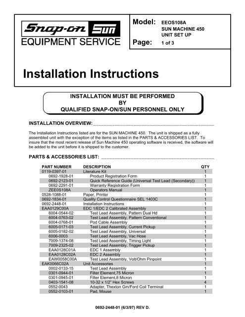
Model: <str<strong>on</strong>g>EEOS108A</str<strong>on</strong>g>SUN MACHINE <str<strong>on</strong>g>450</str<strong>on</strong>g>UNIT SET UPPage: 1 of 3Installati<strong>on</strong> Instructi<strong>on</strong>sINSTALLATION MUST BE PERFORMEDBYQUALIFIED SNAP-ON/SUN PERSONNEL ONLYINSTALLATION OVERVIEW:_____________________________________________The Installati<strong>on</strong> Instructi<strong>on</strong>s listed are for the SUN MACHINE <str<strong>on</strong>g>450</str<strong>on</strong>g>. The unit is shipped as a fullyassembled unit with the excepti<strong>on</strong> of the items as listed in the PARTS & ACCESSORIES LIST. Toinsure that the most recent release of <str<strong>on</strong>g>Sun</str<strong>on</strong>g> <str<strong>on</strong>g>Machine</str<strong>on</strong>g> <str<strong>on</strong>g>450</str<strong>on</strong>g> operating software is received, the software willbe added to the unit before it is shipped to the customer.PARTS & ACCESSORIES LIST: __________________________________________PART NUMBER DESCRIPTION QTY0119-0397-01 Literature Kit 10692-1928-01 Product Registrati<strong>on</strong> Form 10692-2123-01 Quick Reference Guide (Universal Test Lead (Sec<strong>on</strong>dary)) 10692-2291-01 Warranty Registrati<strong>on</strong> Form 1ZEE0S108A Operators Manual 10528-1088-01 Paper, Printer 10692-1834-01 Quality C<strong>on</strong>trol Questi<strong>on</strong>naire SEL 1403C 10692-2448-01 Installati<strong>on</strong> Instructi<strong>on</strong>s 1EAA0129C00A EDC 1/EDC 2 Calibrated Assembly 16004-0544-02 Test Lead Assembly, Pattern Dual Hd 16004-0763-02 Test Lead Assembly, Pattern C<strong>on</strong>venti<strong>on</strong>al 16004-0768-01 Pod Cable Assembly 16005-0171-03 Test Lead Assembly, Current Pickup 16005-0182-02 Test Lead Assembly, Universal 16006-0003 Test Lead Assembly, Vac Hose 17009-1374-08 Test Lead Assembly, Timing Light 17009-2325-02 Test Lead Assembly, Trigger Pickup 1EAA0128C01A EDC 1 Assembly 1EAA0128C02A EDC 2 Assembly 1EAW0058C00A Test Lead Assembly, Volt/Ohm Pinpoint 1EAK0066C02A Unit Accessories 10002-0133-15 Test Lead Assembly 10301-0944-01 Filter Element,75 Micr<strong>on</strong> 10301-0945-01 Filter Element,8 Micr<strong>on</strong> 10403-1541-08 10-32 x 1/2” Hex Screws 40552-0043 Adapter, Thext<strong>on</strong> Gm/Ford Coil Terminal 10552-0103-01 Pad, Mouse 10692-2448-01 (6/3/97) REV D.
Page 2 of 3PART NUMBER DESCRIPTION QTY0552-0116-01 Mouse, 3 Butt<strong>on</strong> Black 10552-0120-01 Adapter, Thext<strong>on</strong> Chry/Jeep/Eagle 10647-0170 Tee 10669-0220 Hose, Poly, 1/4 Id 24”0669-0623 Hose 10669-0733 Hose 10669-0734 Hose 10672-0035-01 Test Clip 10682-1049-01 Labels, Stickers 10692-2406-01 Banner 10787-0035 Cap 11747-0101 Test Adapter Assembly, Pat Pickup 11747-0102 Test Adapter Assembly, Hei Pickup 12161-0023 Hangers 43988-0255-01 Test Assembly, Exhaust Hose 3/16" 16002-0346 Test Lead Assembly 16002-0349 Jumper 16004-0544-02 DIS Pickup Assembly 16004-0775-02 Cable, Sec<strong>on</strong>dary “Y” Adapter 16004-0819-01 Adapter, Universal Pattern Pickup 16006-0003-02 Lead Assembly, Source Vac Hose 17009-1869-01 Test Assembly, Exhaust Probe Assembly 17009-2334-03 Test Lead Assembly, Mag Probe 17049-0004-01 Oxygen Sensor 17054-0062 Adapter, Chry C2 Mag 1EAW0060C00A Cable, Adapto 1EERC102A Remote C<strong>on</strong>trol 1REQUIRED TOOLS: ____________________________________________________• Complete Tool KitINSTALLATION INSTRUCTIONS: _________________________________________NOTE: Steps 1 through 6 will require two or more people.1. Cut and remove the straps. Carefully slide the unit cart<strong>on</strong> off of the shipping pallet. Remove the top ofthe shipping cart<strong>on</strong>.2. Locate the <str<strong>on</strong>g>Sun</str<strong>on</strong>g> <str<strong>on</strong>g>Machine</str<strong>on</strong>g> <str<strong>on</strong>g>450</str<strong>on</strong>g> Operating Software Package. The software could be located <strong>on</strong> theoutside of the cart<strong>on</strong> or <strong>on</strong> the inside if there is a slot in the shipping cart<strong>on</strong>. Remove the softwarepackage and set aside.3. Remove the cart<strong>on</strong> by sliding the cart<strong>on</strong> over top of the unit.4. Remove foam packing from around the sides of the unit.5. Lean the <str<strong>on</strong>g>Sun</str<strong>on</strong>g> <str<strong>on</strong>g>Machine</str<strong>on</strong>g> <str<strong>on</strong>g>450</str<strong>on</strong>g> so that half of the foam base can be removed.6. Lean the <str<strong>on</strong>g>Sun</str<strong>on</strong>g> <str<strong>on</strong>g>Machine</str<strong>on</strong>g> <str<strong>on</strong>g>450</str<strong>on</strong>g> so that other half of the foam base can be removed.7. Remove tape from ALL drawers and covers.8. Remove bubble wrap from Keyboard, located in the keyboard drawer.9. Inventory all items using the Parts & Accessories List and inspect for damage. The Unit Accessoriesare located in the bottom drawer of the unit. The Literature Kit is also located in the bottom drawer ofthe unit.NOTE: Any software or hardware owners’ manuals and pre-loaded software thatcome with the computer, such as Microsoft® DOS and Windows 3.11, arelocated in the bottom drawer of the unit.0692-2448-01 (6/3/97) REV D.
Page 3 of 3NOTE: Any REGISTRATION CARDS for the installed software such as Microsoft®DOS, Microsoft® Windows must be filled out and sent in by the customer toensure compliance with any software licensing agreements.10. Locate the four hangers (2161-0023) and the four 10-32 x 1/2” Hex Screws (0403-1541-08). Attachtwo hangers to the left side and two to the right side of the unit using the hex screws.11. The M<strong>on</strong>itor and M<strong>on</strong>itor Base Kit are shipped separately from the unit. Follow the Installati<strong>on</strong>Instructi<strong>on</strong> found in the M<strong>on</strong>itor Base Kit to install the M<strong>on</strong>itor.12. Discard the A.C. Cable supplied with the M<strong>on</strong>itor. Use the A.C. Cable found attached to the top of theunit.13. Locate the Mouse and install the Mouse cable end to COM 2: c<strong>on</strong>nector of the c<strong>on</strong>nector plate <strong>on</strong> theleft side of the unit.14. Locate the printer paper (0528-1088-01) in the bottom storage drawer. Load printer paper into papercassette of the Printer (100 Sheets maximum). A porti<strong>on</strong> of the remaining paper can be placed underthe Printer.15. There are two choices for EDC POD placement <strong>on</strong> the <str<strong>on</strong>g>Sun</str<strong>on</strong>g> <str<strong>on</strong>g>Machine</str<strong>on</strong>g> <str<strong>on</strong>g>450</str<strong>on</strong>g>. The first choice is the EDCPod holder kit; the sec<strong>on</strong>d is a Boom kit. These kits are shipped separately from the unit. Locate thekit that was shipped with your unit and follow the installati<strong>on</strong> instructi<strong>on</strong>s supplied with the kit. Once thekit is installed, proceed to the next step.16. C<strong>on</strong>nect all Test Leads and the Vacuum Hose to the respective c<strong>on</strong>nectors located <strong>on</strong> the EDC PODsof the <str<strong>on</strong>g>Sun</str<strong>on</strong>g> <str<strong>on</strong>g>Machine</str<strong>on</strong>g> <str<strong>on</strong>g>450</str<strong>on</strong>g>. Store any unused leads and accessories in the lower storage drawer.17. Locate the Oxygen Sensor (7049-0004-01) in the accessories bag. Remove the back panel of thetester. Install the Oxygen Sensor into the block and c<strong>on</strong>nect the wiring harness to the top of the sensor.18. Get the <str<strong>on</strong>g>Sun</str<strong>on</strong>g> <str<strong>on</strong>g>Machine</str<strong>on</strong>g> <str<strong>on</strong>g>450</str<strong>on</strong>g> software package that was set aside in step 2. Using the installati<strong>on</strong>instructi<strong>on</strong>s provided in the software package, install the CD ROM Software into the <str<strong>on</strong>g>Sun</str<strong>on</strong>g> <str<strong>on</strong>g>Machine</str<strong>on</strong>g> <str<strong>on</strong>g>450</str<strong>on</strong>g>.19. When installing the software you will be prompted to call SUN PARTS DEPARTMENT for a validati<strong>on</strong>code. Once the code has been entered, proceed through the set up screens until you get the choices ofExpress Setup or Custom Set up. Enter Custom Setup and from the custom setup screen select thefollowing:Install <str<strong>on</strong>g>Sun</str<strong>on</strong>g> <str<strong>on</strong>g>Machine</str<strong>on</strong>g> softwareInstall Oki OL600 DOS C<strong>on</strong>trol Paneland press ‹.20. Follow the screen prompts to complete the software loading. Refer to the <str<strong>on</strong>g>Sun</str<strong>on</strong>g> <str<strong>on</strong>g>Machine</str<strong>on</strong>g> 500 ServiceManual Chapter 5 for proper printer setup through the c<strong>on</strong>trol panel.NOTE: Do Not load the Okadata OL600e Windows drivers from the Software SupportDisks. Set up Windows using the HP-IIP printer driver for this printer.21. Complete the Field Quality C<strong>on</strong>trol Questi<strong>on</strong>naire SEL 1403C (0692-1834-01) and follow theinstructi<strong>on</strong>s <strong>on</strong> the form for mailing.22. Insert these Installati<strong>on</strong> Instructi<strong>on</strong>s in the rear of the <str<strong>on</strong>g>Sun</str<strong>on</strong>g> <str<strong>on</strong>g>Machine</str<strong>on</strong>g> <str<strong>on</strong>g>450</str<strong>on</strong>g> Service Manual when <strong>on</strong>ebecomes available for future reference.NOTE: This tester is equipped with a 4-gas analyzer: see the Emissi<strong>on</strong>s Chapter ofthe <str<strong>on</strong>g>Sun</str<strong>on</strong>g> <str<strong>on</strong>g>Machine</str<strong>on</strong>g> 500 Service Manual for the calibrati<strong>on</strong> and checkout.INSTALLATION COMPLETENOTE: There are several upgrade kits that are available for the <str<strong>on</strong>g>Sun</str<strong>on</strong>g> <str<strong>on</strong>g>Machine</str<strong>on</strong>g> <str<strong>on</strong>g>450</str<strong>on</strong>g>.Before installing any of these kits verify the proper operati<strong>on</strong> of the unit.Install the kits <strong>on</strong>e at a time verifying proper operati<strong>on</strong> of the unit and upgradeprior to installing the next upgrade kit.0692-2448-01 (6/3/97) REV D.


