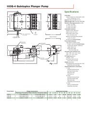
P15/PV15 - Process Pumps
P15/PV15 - Process Pumps
P15/PV15 - Process Pumps
- No tags were found...

You also want an ePaper? Increase the reach of your titles
YUMPU automatically turns print PDFs into web optimized ePapers that Google loves.
Section 3HOW IT WORKS—PUMPThe Wilden diaphragm pump is an air-operated, positive displacement, self-priming pump. These drawings show flow patternthrough the pump upon its initial stroke. It is assumed the pump has no fluid in it prior to its initial stroke.FIGURE 1 The air valve directs pressurizedair to the back side of diaphragm A. Thecompressed air is applied directly to theliquid column separated by elastomericdiaphragms. The diaphragm acts asa separation membrane between thecompressed air and liquid, balancing theload and removing mechanical stressfrom the diaphragm. The compressedair moves the diaphragm away fromthe center of the pump. The oppositediaphragm is pulled in by the shaftconnected to the pressurized diaphragm.Diaphragm B is on its suction stroke; airbehind the diaphragm has been forcedout to atmosphere through the exhaustport of the pump. The movement ofdiaphragm B toward the center of thepump creates a vacuum within chamber B.Atmospheric pressure forces fluid intothe inlet manifold forcing the inlet valveball off its seat. Liquid is free to movepast the inlet valve ball and fill the liquidchamber (see shaded area).FIGURE 2 When the pressurized diaphragm,diaphragm A, reaches the limit of its dischargestroke, the air valve redirects pressurizedair to the back side of diaphragm B. Thepressurized air forces diaphragm B awayfrom the center while pulling diaphragm Ato the center. Diaphragm B is now on itsdischarge stroke. Diaphragm B forces theinlet valve ball onto its seat due to thehydraulic forces developed in the liquidchamber and manifold of the pump. Thesesame hydraulic forces lift the dischargevalve ball off its seat, while the oppositedischarge valve ball is forced onto its seat,forcing fluid to flow through the pumpdischarge. The movement of diaphragm Atoward the center of the pump creates avacuum within liquid chamber A. Atmosphericpressure forces fluid into the inletmanifold of the pump. The inlet valve ballis forced off its seat allowing the fluid beingpumped to fill the liquid chamber.FIGURE 3 At completion of the stroke,the air valve again redirects air to theback side of diaphragm A, which startsdiaphragm B on its exhaust stroke. Asthe pump reaches its original startingpoint, each diaphragm has gone throughone exhaust and one discharge stroke.This constitutes one complete pumpingcycle. The pump may take several cyclesto completely prime depending on theconditions of the application.HOW IT WORKS—AIR DISTRIBUTION SYSTEMThe Pro-Flo ® patented air distribution system incorporates twomoving parts: the air valve spool and the pilot spool. The heart ofthe system is the air valve spool and air valve. This valve designincorporates an unbalanced spool. The smaller end of the spoolis pressurized continuously, while the large end is alternatelypressurized then exhausted to move the spool. The spool directspressurized air to one air chamber while exhausting the other.The air causes the main shaft/diaphragm assembly to shift toone side — discharging liquid on that side and pulling liquid inon the other side. When the shaft reaches the end of its stroke,the inner piston actuates the pilot spool, which pressurizes andexhausts the large end of the air valve spool. The repositioningof the air valve spool routes the air to the other air chamber.WIL-10110-E-02 8/06 3 WILDEN PUMP & ENGINEERING, LLC