Bridges - Buro Happold
Bridges - Buro Happold
Bridges - Buro Happold
- No tags were found...

You also want an ePaper? Increase the reach of your titles
YUMPU automatically turns print PDFs into web optimized ePapers that Google loves.
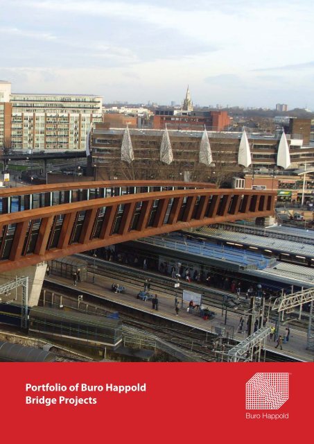
Portfolio of <strong>Buro</strong> <strong>Happold</strong>Bridge Projects
Contents<strong>Buro</strong> <strong>Happold</strong>Project ExamplesPonte Della MusicaM8 Harthill FootbridgeBaakenhafen BruckeRiver Dove BridgeStratford <strong>Bridges</strong> 2 & 3King Abdul Aziz FlyoverAlexandra BridgeClarence Dock Fixed BridgeMetro West LiffeyEmirates Stadium <strong>Bridges</strong>Stratford Town Centre LinkCanford FootbridgeThorne Pedestrian Swing BridgeGreenside Place Link BridgeMobius BridgeWroxham BridgeNovi Sad Friendship BridgeCalden Canal BridgeMulti-Storey Car Park Link BridgeSackler CrossingBaylor University BridgeNational Aquarium BridgeAtwater BridgeRector Street BridgeOrange County Great ParkDulles Corridor MetrorailHigh LineMill River Bridge4 Mile Run BridgeHarvard Alston Science ComplexCharles River Bridge
Ponte della MusicaRome, Italy<strong>Buro</strong> <strong>Happold</strong>In 2000 an international design competition was organisedby the Comune di Roma (the Municipality of Rome)for a new pedestrian bridge to cross the river Tiber.The first such bridge to be built in the city since Romantimes. The proposal by <strong>Buro</strong> <strong>Happold</strong> and Powell-WilliamArchi-tects was awarded first prize and subsequentlydeveloped for construc-tion.The winning scheme comprised two leaning steel archessupporting a steel deck. The total length of the bridgeis approximately 200m long, with a clear span of 130mbetween arch springing points. The springing points, inconcrete, incorporate staircases providing access fromthe river bank up to deck level. The deck itself is designedfor pedestrian usage but with provision for futureincorporation of a tramway.One of the important features of this bridge is that itconnects the Olympic Stadium in Rome with QuartiereFlaminio for the first time in 100 years.Following the competition the client appointed the winningteam, as-sisted by local firm, C. Lotti e Associati, todevelop the design to tender status; the detailed designwas undertaken by the contractor. Construc-tion of thebridge commenced in late 2008 and was completed anopened to the public in June 2011.Key project informationClientArchitectLocal EngineerMain ContractorFabricatorConstruction ValueServices provided by <strong>Buro</strong> <strong>Happold</strong>Comune di RomaPowell-Williams ArchitectC Lotti E AssociatiConstraMaeg€10.5mBridge engineering, infrastructure and transport engineering
M8 Harthill FootbridgeGlasgow, UKThe existing motorway overbridge at the Heart ofHarthill Services had fallen into a state of disrepair andfailed to comply with the requirements set-out in theDisability Discrimination Act (DDA) 1995. <strong>Buro</strong> <strong>Happold</strong>became the detailed designers after submittingthe preferred tender design in a team that includedcontractor Raynesway Construction Ltd and steelfabricator SHStructures.The scheme is a 90m helical truss with approach rampsand stairs. The bridge spans the M8 carriageway at highlevel, providing an iconic crossing for all users and alandmark symbol for drivers passing underneath.Prefabrication at every stage of the design was used tocreate an efficient construction phase where the mainspan was delivered to site in six sections and weldedtogether to create one unit. A complicated lift processsaw the one complete piece being raised over theexisting bridge and lowered onto discrete piers.The approach ramp structures are significant inthemselves and compliment the main span with tubularhollow sections and a bespoke parapet system thatreplicates the inclined helical grid.The footbridge was a finalist in the British ConstructionIndustry Awards 2009 and highly recommended in theACE and Saltire Awards..Key project informationClientTransport ScotlandContractor Raynesway Construction LimitedProject value £6,000,000Dates Constructed 2008Bridge Capability Statement6
<strong>Buro</strong> <strong>Happold</strong>7
Baakenhafen Brucke WestHamburg, GermanyThe Baakenhafen Brucke West will form an importantnew link into the major new harbour developmentin Hamburg. Comprising three traffic lanes within its21m width, it will also have cycle lanes and undulatingcantilever walkways providing a fluid form along bothsides and terraces with seating. The bridge will havethree spans and is a total of 164m in length. Unusually itincorporates a 30m long lift out section in its centre thatcan be removed by barge should there be a future needfor large vessels to pass through.<strong>Buro</strong> <strong>Happold</strong> have undertaken the full detailedengineering design of the bridge. The superstructureis a steel orthotropic plate deck on a ladder beamarrangement of transverse ribs connecting to ageometrically complex varying depth stiffened steelbox girders. The substructure consists of traditionalconcrete abutments at each end with intermediate piersthat will be formed from precast concrete shells loweredover bored under-reamed piles. Advanced analyticalmethods were required in order to undertake the designand great care was taken in the development of thebridge detailsThe project was won via an international designcompetition by a team comprising a joint venture of<strong>Buro</strong> <strong>Happold</strong> and Wilkinson Eyre at the end of 2011.The construction phase commenced in May 2012Key project informationClientHafen City HamburgArchitect Wilkinson EyreProject Value €12mDate Due for completion in 2013Services Provided by <strong>Buro</strong> <strong>Happold</strong>Bridge Capability StatementBridge engineering, mechanical and electrical design,construction supervision8
<strong>Buro</strong> <strong>Happold</strong>9
River Dove BridgeDerbyshire, UK<strong>Buro</strong> <strong>Happold</strong> was commissioned, as part of a Designand Build contract with Laing O’Rourke to designthe new Foulstone and Wombwell school and all theassociated infrastructure. One aspect of this was therequirement for a new crossing of the River Dove toform the primary vehicular access into the school.The bridge has a clear span of 21.5m and is a fullyintegral structure with the deck comprised of precastprestressed beams. Working with Laing O’Rourke’s inhouseprecast production facility, <strong>Buro</strong> <strong>Happold</strong> carriedout the full detailed design of the bridge which alsoincorporated precast units to provide a high qualityfinish to the end abutments.The surface is designed for combined use by vehicles,pedestrians, cyclists and horses. As it is a bridleway, theedge parapets are 1.8m high. The bridge is constructedto adoptable standards.The bridge was successfully completed in time for theschool opening in Autumn 2012.Key Project InformationClientBarnsley MBCContractorLaing O’RourkeProject ValuePart of a £55m schemeDates Opened 2012Services Provided by <strong>Buro</strong> <strong>Happold</strong>Bridge engineering, geotechnical design, mechanicaland electrical design, construction supervision.Bridge Capability Statement10
Stratford City Link <strong>Bridges</strong> 2 & 3London, UK<strong>Buro</strong> <strong>Happold</strong>Two new bridges which will link Stratford Town Centreto the new Olympic Village. Both bridges span railwayinfrastructure (above and below ground) which belongto CTRL (Channel Tunnel Rail Link) and Network Rail.<strong>Buro</strong> <strong>Happold</strong> was brought on board by the contractorto provide tender and detailed design services. <strong>Buro</strong><strong>Happold</strong> also provided support in seeking technicalapproval from the authorities. These included Form A(Tender Approval), Form B (Design Check Statement)and Form C (Design & Check of Temporary Works).Advanced soil-structure interaction modelling was usedto determine the impact of construction on adjacentstructures and infrastructure, which enabled CTRLplanning approval.Some of the construction work was undertakenduring track possession time (lifting of deck ontobridges). However, the significant proportion of workwas undertaken during normal operating times. Thisrequired extensive liaison with Network Rail and CTRLto ensure the works were undertaken in the correctmanner, and that all necessary approvals were in place.A close working relationship with the contractor wasessential to improve on the generic concept designproduced by others and to ensure buildability.Key Project InformationClientBovis Lend LeaseContractorVolker FitzpatrickDates Opened 2012Services provided by <strong>Buro</strong> <strong>Happold</strong>Ground engineering, bridge engineering11
King Abdul Aziz FlyoverRiyadh, KSAThe flyover carries vehicular traffic on the King Abul Azizroad over King Abdullah road in the centre of Riyadhin the Kingdom of Saudi Arabia. It will carry six lanes oftraffic, three in each direction.The flyover consists of a main steel arch 81.5m span overKing Abdullah Road with two approach multi-span bridgeseach comprising 5 spans (25m,30m,30m,30m,25m). Thetotal length of the elevated structure is 361.5mThe approach spans comprise post-tensioned voideddeck slab prestressed in both the longitudinal andtransverse directions.The piers support the voided deck via two bearingspositioned 3.5m from the bridge centre line. A spanby-spanmethod of construction is proposed for theapproaches. With the exception of the first and last span,the spans approximately start at a fifth span point andextend to the fifth span point of the next span.The central span is an 81.5m tied arch comprising afabricated steel box girder with an orthotropic steel decksystem consisting of closed longitudinal ribs and deckingplates. The steel deck is supported by cable systemsuspending from a single fabricated steel arch. The arch issupported at either end by a pier, which also supports theapproach deck, via two independent bearings positioned3.5m from the bridge centre line.The flyover will be designed to KSA standards inconjunction with ASHTO LRFD for all concrete elementsand BS 5400 for steelwork design.Key project informationBridge Capability StatementClientArriyadh Development Authority (SA)Contractor Saudi Oger LimitedProject value ConfidentialDate Scheme and detailed design 2011Construction started Sep 2011Services provided by <strong>Buro</strong> <strong>Happold</strong>Bridge engineering, ground engineering andsite supervision.12
Alexandra Arch BridgeSingaporeThe project was won in an International Design competitionorganised by the Singaporean governement in 2003. TheBridge Group at <strong>Buro</strong> <strong>Happold</strong> provided support to <strong>Buro</strong><strong>Happold</strong> office in Singapore who were part of a teamworking with local consultants LOOK Architects and Ecas-EJConsultants as a local engineering partner. The team wonthe commission for the bridge and also a 1.6km elevatedwalkway structure. The Bridge Group undertook concept anddetailed design of the bridge.The bridge is designed for pedestrian and cyclist traffic.It is an asymmetric structure comprising a single leaningarch supporting a deck profiled in cross section and curvedin plan by means of hanger fins. The arch rises 17m aboveground level with 60m between the springing points. The 4mwide granite-surfaced deck has a total length of 80m and isdesigned to act as a torsion box. The arch, deck and fins areall fabricated from steel with the whole assembly supportedby raking concrete piers founded on piled foundations.Construction started in Summer 2006 and the bridge wasopen to the public on May 10th 2008 by the Prime Minister ofSingapore, Lee Hsien Loong.Key Project InformationClientUrban Regeneration AuthorityValue£2.2mDates Opened 2008Services provided by <strong>Buro</strong> <strong>Happold</strong>Bridge EngineeringBridge Capability Statement14
<strong>Buro</strong> <strong>Happold</strong>15
Clarence Dock Fixed BridgeLeeds, UKThe Clarence Dock development is at the heart of Leedsand is the city’s new premier development located nextto the Royal Armouries building. The client was requiredto build a pedestrian bridge over the River Aire to fulfillthe section 106 agreement.<strong>Buro</strong> <strong>Happold</strong> were employed to carry out the feasibilitystudy, develop the bridge concept, and obtain thestatutory, legal and planning approvals for the bridge.The detailed design was undertaken by the contractorbut <strong>Buro</strong> <strong>Happold</strong> were retained to oversee constructionon behalf of the client.The bridge has a cable stayed deck supported fromtwo leaning frames. The design was inspired by cranes,making reference to the industrial heritage of the site.The bridge was lifted onto a central island using an 800tonne crane and was swung into position using a systemof temporary cables, tirfors and floating pontoons.Construction was completed in 2004.Key Project InformationClientBerkeley Clarence Dock CompanyContractor SpencerValue £1mDates Opened 2008Services provided by <strong>Buro</strong> <strong>Happold</strong>Bridge EngineeringBridge Capability Statement16
<strong>Buro</strong> <strong>Happold</strong>17
Metro West RiverLiffey BridgeDublin, Ireland<strong>Buro</strong> <strong>Happold</strong> collaborated closely with ExplorationsArchitecture on an international competition winningentry to cross the River Liffey in Dublin, Ireland. A380m span suspension bridge is proposed as thefirst significant bridge of this type in Ireland and apioneering development in medium span railroadsuspension systems. Its innovative outline will form asymbol for the Dublin light rail system contributing toits already outstanding European reputation, withoutcompromising the natural setting.The structure is designed to minimise the any visualobstruction across the valley perspective. With its lowrise towers and shallow cable profile, the bridge is aniconic yet subtle structure flying delicately over andreflecting the shape of the Liffey Valley.Carrying light rail and pedestrian traffic, the bridgeoffers unique views for all users. The central portion ofthe span consists of a belvedere supporting the deck,while the footway follows the cable profile. The towersconsist of inclined A-frames minimising the bending andmaximising structural efficiency.Key Project InformationClientRailway Procurement AgencyArchitectExploration ArchitectureValue €50mDates Competition win 2009Services provided by <strong>Buro</strong> <strong>Happold</strong>Bridge EngineeringBridge Capability Statement18
<strong>Buro</strong> <strong>Happold</strong>19
Emirates Stadium <strong>Bridges</strong>LondonArsenal Football Club’s new stadium is underconstruction. A new, state-of-the-art stadium has beenproposed that will better serve the aspirations of theClub and its supporters. <strong>Buro</strong> <strong>Happold</strong> ConsultingEngineers are providing civil, structural, access, firesafety and geotechnical engineering services.<strong>Buro</strong> <strong>Happold</strong> Group has developed designs for twoaccess bridges that will serve the new stadium atAshburton Grove in North London. The contract for theconstruction of bridges was awarded on a design andbuild basis.Approvals from Network Rail (Railtrack), LondonUnderground Limited, London Borough of Islingtonand Thames Water for the construction of the bridgeswere obtained by <strong>Buro</strong> <strong>Happold</strong> and the constructionof the bridge was substantially completed in 2004.The construction cost of the bridge structures alone isestimated at about £10m. Both bridges, which crossover commuter and freight railway lines, are of steeltruss construction, comprising steel tubular memberswith a steel/concrete composite deck.The first bridge, which was designed to cater solelyfor pedestrian/crowd access, is around 15m wide andspans a distance of approximately 80m in total. Thisbridge which is 700t was lifted into position in twosections using overhead cranes. The second bridgewhich is approximately 105m long and 22m wide andweighs 1,200t will carry vehicular and pedestrian traffic.It was constructed from the podium side and pushlaunched from one abutment to the other supported byintermediate trestles along the way.Key Project InformationBridge Capability Statement20ClientArsenal Football ClubArchitectHOK SportProject Value £10mConsulting Engineer <strong>Buro</strong> <strong>Happold</strong>ContractorSir Robert McAlpineDates Completed 2004Services Provided by <strong>Buro</strong> <strong>Happold</strong>Bridge Engineering, Ground Engineering & StadiaEngineering
<strong>Buro</strong> <strong>Happold</strong>21
Stratford Town Centre LinkLondon, UKThe Stratford Town Centre Link (STCL) provides a highquality pedestrian and public realm space that connectsWestfield Shopping Centre with the existing facilities inStratford. These two areas historically were severed bythe major railway corridor at Stratford Regional Station.The link crosses the railway in two spans of 64.3m, andprovides a 12m wide clear corridor. It is a half throughbridge structure, comprising Vierendeel trusses alongeach side. The trusses are characterised by having notriangulated elements and instead rely on frame actionprovided by the top and bottom chords and verticalelements, which are rigidly connected. For structuralefficiency, the two main trusses vary in depth from aminimum at the ends of the bridge and are increased toa maximum at the central pier.It will also be an important access route for the 2012Olympics.Key project informationClientWestfield Shopping TownsArchitect Knight ArchitectsProject value £35mServices provided by <strong>Buro</strong> <strong>Happold</strong>Conceptual design, scheme design, technical approval,planning, detailed designThe structure is fabricated from weathering steel, which,due to its stable rust layer, requires no painting. Thishas significant maintenance benefits in the railwayenvironment. The truss elements are so large thatspecially fabricated sections were required and providedthe opportunity for visually interesting and varying trussmembers with irregular polygonal cross sections. Designwas carried out during 2008 and 2009 and constructionduring 2010 and 2011.The high sides to the structure protect the railway fromfalling or thrown objects. Special glazing tests, involvingthe dropping of a steel sphere from a height of 15m,were carried out to prove the integrity of the laminatedglass to the approval authorities. The bridge lighting,which is simple yet striking, is effective in providing awell lit and non-threatening environment for users atnight.Bridge Capability Statement22An ingenious method of incremental launchingwas used for the bridge installation, which had tobe considered from an early stage in the bridgedesign. Showing considerable foresight, the Clientcommissioned a computer animation to clearlycommunicate the complex sequencing to the approvalauthorities and operatives. This culminated in the firstknown live bridge launch over an operational station inthe UK.The Westfield Shopping Centre was opened to thepublic in September 2011 and the bridge is popularlyused as the main access to the retail area.
<strong>Buro</strong> <strong>Happold</strong>23
Canford FootbridgeDorset, UK<strong>Buro</strong> <strong>Happold</strong> developed both the architectural andstructural concept, as well as preparing the detaileddesign, for a replacement footbridge that is to beconnected to an existing grade II listed masonry archbridge near Wimborne in Dorset.The new steel structure is to be supported from theexisting masonry arch bridge. The lateral and eccentricloads imposed by the new bridge required analysisand refurbishment of the existing arch structure wasrequired to provide an acceptable load path to theshared foundations.New piled foundations were required to supplement theexisting foundations and are located in a river and in aflood planeThe bridge was completed in early 2009 and was highlycommended in the 2009 IStructE awards.Key project informationClientBorough of PooleContractor CarillionProject value £2mDates Opened 2008Services provided by <strong>Buro</strong> <strong>Happold</strong>Bridge EngineeringBridge Capability Statement24
<strong>Buro</strong> <strong>Happold</strong>25
Thorne PedestrianSwing BridgeYorkshire, UKThe flyover across Stainforth and Keadby Canal inThorne is a crossing shared by traffic on the busy A614with pedestrian and cyclists. The client commissioned<strong>Buro</strong> <strong>Happold</strong> to provide consultancy services forconcept development, obtaining technical approvalsand town and country planning permission, contractadministration, detailed design of the structure,foundations and the moving mechanism andsupervision of construction for a bridge crossing thecanal.<strong>Buro</strong> <strong>Happold</strong> in conjunction with Broadway Malyan andThomson Engineering Consultants developed a numberof fixed and moveable bridge options. Ultimately amoveable bridge option was proposed and acceptedwhich satisfies the strict requirements of BritishWaterways requiring the canal to be navigable at alltimes. The scheme was completed in 2005.The bridge is an asymmetric swing bridge of a noveldesign with the pintle (pivot) located above and to theside of the deck and a counterweight which is located tothe side of the bridge. The length of the bridge is 16m.The deck construction consists of a configuration oftubular steel members. The bridge can be opened by ahydraulic mechanism housed in an enclosure.The project value was about £320,000. The bridge wona commendation in the ‘Community’ Category in theWaterways Renaissance Awards 2006Bridge Capability StatementKey Project InformationClientSilver Street Visions Thorn &Moorends RegenerationArchitectBroadway MalyanM&E EngineerThompson EngineeringConsultantsDates Constructed 2005Services provided by <strong>Buro</strong> <strong>Happold</strong>Bridge Engineering26
<strong>Buro</strong> <strong>Happold</strong>27
Greenside Place Link BridgeEdinburgh, UK<strong>Buro</strong> <strong>Happold</strong> worked closely with Broadway MalyanArchitects for the design of a new pedestrian bridgeover Leith Street in the heart of Edinburgh City centre.The bridge, which was opened to the public in April2004, connects the St James Shopping Centre on oneside of Leith Street to an extended Nottingham car parkterminal on the other which was also part of the project.The footbridge is supported on slender V-shapedcolumns and has a total length of 50m. It has a complexgeometry with an S-shaped curvature in plan.The structure consists of an aluminium deck supportedby hollow sections actively integrating with a system ofhelical tubes that wrap around the deck. It has a glazedroof and balustrades.The Greenside Place Bridge Link was the winner of2004 Saltire Society design award and has also won theprestigious Institution of Structural Engineers StructuresSpecial Award in 2005. The cost of construction of theproject was approximately £1.9m.Key Project InformationClientLaSalle InvestmentManagementArchitectBroadway Malyan ArchitectsConsulting Engineer <strong>Buro</strong> <strong>Happold</strong>ContractorBalfour Beatty RayneswayValue£1.9mDates Completed 2004Services Provided by <strong>Buro</strong> <strong>Happold</strong>Bridge Engineering, Building Engineering, GroundEngineering & Facade EngineeringBridge Capability Statement28
<strong>Buro</strong> <strong>Happold</strong>29
Mobius BridgeBristol, UK<strong>Buro</strong> <strong>Happold</strong> worked together with Hakes Associatesto win this competition. The winning design wasinspired by a ‘Mobius strip’, the name of a mathematicalform named after the mathematician August Mobius.A mobius strip is formed when one end of a longrectangular strip is twisted through 180 degreesand then joined to the other end to create a threedimensional object with only a single surface.The final design exhibits an intriguing mix of simplicityand complexity with the mobius strip manipulatedto provide an arch and a deck whilst maintaining themathematical form. The main span comprises a steelarch in compression, with the deck suspended byrelatively small diameter hanger cables. A connectionexists between the arch and the deck where the twocross over and the deck section spans the remainingdistance to the end as a beam. The deck, arch and pierare one and the same and it gives the structure aneconomy and lightness. The geometry of the bridge hasbeen carefully chosen to produce an effective structuralsolution that satisfies the site constraints.The bridge, once constructed, will create an instantlyrecognisable land mark. The team has already gainedplanning permission for the design and has beenretained by the client to progress the project in tothe detailed design phase with construction due forcompletion in 2013.Key Project InformationClientH D G ManrurArchitectHakes AssociatesProject value£1.7mDatesOngoingServices provided by <strong>Buro</strong> <strong>Happold</strong>Bridge Capability StatementGeometry and form optimisation, bridge structuralengineering, ground engineering, wind studies andcatergory 3 checks.30
<strong>Buro</strong> <strong>Happold</strong>31
Wroxham FootbridgeNorfolk Broads, UKWroxham Footbridge carries the A1151 footway overthe River Bure to link the communities of Wroxham andHoveton. The bridge was designed for Norfolk CountyCouncil by <strong>Buro</strong> <strong>Happold</strong>.An existing bridge over the River Bure was demolishedand replaced by a new 30m cable stay structure. Thesteel super structure is supported by pairs of forestaysand backstays attached to an 11m A- frame. Theforestays divide the main span into two approximatelyequal spans in order to reduce the depth of the mainlongitudinal girder supporting the deck. Transversediaphragms provide torsional rigidity to the deck andtransfer eccentric loads onto the main girders.The open deck section allows space for gas, water,electricity, foul water and telecommunication ducts.The underside of the deck is enclosed by advancedcomposite materials (fibre reinforced polymer panels)that are lightweight, durable, and unobtrusive.The 44 tonne steelwork was lifted into place by a 500tonne mobile crane during a single road and riverclosure in March 2003. The bridge was constructed at acost of approximately £600,000.Key Project InformationClientNorfolk County CouncilContractorBrehenyDates Constructed 2003Services provided by <strong>Buro</strong> <strong>Happold</strong>Bridge EngineeringBridge Capability Statement32
Novi Sad Friendship BridgeNorwich, UKThe bridge is named in honour of twinning linksbetween Norwich and Novi Sad. The project is theprovision of a new swing bridge and its approaches tocarry a footway and cycleway over the River Wensum inNorwich.The footway and cycleway, which is 4.5m wide, is animportant element in creating pedestrian and cycle linksbetween the Riverside Development and the City Centreareas.The bridge is a cable stayed structure with a main spanlength of 30m. The total length of the crossing is 70mwith side spans of about 10m length. The structure hasa light steel deck which is open in section. A hybrid fan/harp arrangement of stays supports the deck. The bridgerotates about the centre pedestal where a pair of towerssupports the stays.Key Project InformationClientNorfolk County CouncilContractorMay GurneyArchitectRonald YeeValue£1.1m33
Caldon Canal FootbridgeStoke-on-Trent, UKThe new steel bridge is the first phase of a masterplanby RENEW North Staffordshire to redevelop the areajust south of Hanley city centre. The development willprimarily involve new residential housing, but alsoincludes refurbishment of the famous BridgewaterPotteries Workshops which are located on the site.Opened in April 2009, the bridge is an important andeye-catching link in the new pedestrian route throughthe site between Hanley city centre and the newdevelopment.The bridge has been given special attention in themasterplan as it is viewed as setting the tone for therest of the development, and once complete will be avisually stunning structure with some unique features.These include a 3D patterned soffit, formed from adiagonal grillage of steel beams with custom-madealuminium coffers between them; a cantilevering glassbalustrade providing the edge protection; and anunusual arrangement on the south bank of the canalwhere the abutment appears to just touch the bridgedeck without any visible support.Key Project InformationClientRENEW North StaffordshireArchitectNORDValue £1mDates Completed 2009Services provided by <strong>Buro</strong> <strong>Happold</strong>Structural, bridge and ground engineering; costmanagement.Bridge Capability Statement3434
<strong>Buro</strong> <strong>Happold</strong>35
Multi-Storey Car Park Link BridgeTerminal 3, Heathrow AirportLondon, UKThis significant structure forms a pedestrian connectionto the new 2000+ space multi-storey car park fromTerminal 3 at Heathrow. It is now a recognisable featurecrossing over the main airport ring road.The bridge consists of two inclined steel arches thatmeet at midspan. The arch springing points are tied bya truss structure from which enclosed modular units aresuspended by macalloy bar hanger rods. The arches areformed from 666mm diameter circular hollow sectionsthat are bent to radius. The truss also consists of tubularsteel members. The bridge has a 45 degree skew at itsends.<strong>Buro</strong> <strong>Happold</strong>’s bridge engineering departmentdeveloped the concept for the link bridge and preparedfully detailed drawings for construction. Connectiondetails were designed to assist build-ability whilstconcealing bolted splices in the most visible members.One end of the bridge connects to the terminal buildingat the location of an existing link structure that is tobe demolished. Careful phasing of the work has beennecessary to avoid disruption due to closure of the link.Key Project InformationClientBAAArchitectGMWConsulting Engineer GMWM & EWSPContractorLaing O’ RourkeProject Value£1.3mDate Completed in 2006Bridge Capability StatementServices Provided by <strong>Buro</strong> <strong>Happold</strong>Bridge Engineering, Geotechnical Engineering &Construction Advice36
The Sackler Crossing Royal Botanic Gardens KewLondon, UK<strong>Buro</strong> <strong>Happold</strong> was commissioned to design a crossingover the Lake at Kew Gardens in collaboration withJohn Pawson Architects. The lake crossing at Kew formsa component of a larger vision for the Royal BotanicGardens. Taking the Palm House as the central pointof a notional circle, a grand circulation axis is createdthrough the landscape. The Lake crossing spans asection of the route which lies across the water.The bridge consists of a steel structure bolted down toconcrete piers spaced across the lake at approximately8m centres. The piers are steel oval-section columnsfounded on driven tubular piles. The main spinemembers are a pair of beams of rectangular hollowsection fabricated from steel plate. These are attachedto square members by tapering depth outriggers/finsapproximately 2m centres.Bronze balusters are fixed to the edge members withbolted connections. Granite planks are attached tothe steelwork using dowelled connections with hardneoprene pads placed between steel and stone.The project was completed in May 2006 and has beencommended for the high quality achieved in thenational press.Key Project InformationClientRoyal BotanicGardens, KewArchitectJohn PawsonProject Value£1.5mEngineer & Project Manager <strong>Buro</strong> <strong>Happold</strong>Length70mDates Completed in 2006Bridge Capability StatementServices Provided by <strong>Buro</strong> <strong>Happold</strong>Bridge Engineering, Ground Engineering38
<strong>Buro</strong> <strong>Happold</strong>39
Baylor University BridgeWaco, TX, USAThe Baylor University Bridge will provide access andconnection to the new Baylor Football Stadium, alsoengineered by <strong>Buro</strong> <strong>Happold</strong>, that will be constructedacross the Brazos River north of the main campus. Asthe Brazos river is dammed downstream, this portionof the river becomes a long lake called Lake Brazos. Thewater level is consistent and calm allowing for a floatingisland structure accessible from the south or campusside to be constructed alongside and below the bridgestructure. This floating island will accommodate campusgatherings and activities and will have the provision fordocking boats.The bridge is approximately 500 feet in lengthconfigured in a gentle curving arc across Lake Brazos.The bridge is supported by one pier adjacent tothe floating island structure keeping approximately2/3rd of the width of the lake navigable. The bridgeis approximately 30 feet wide to accommodate largenumbers of people for campus events and footballgames. The design is intended to not only providea comfortable crossing but along the way will beopportunities for gathering, possibly seating as well asviewing the river landscape and the new stadium.The intent of the bridge design is to develop an iconicsignature structure that is scaled to the campus andannounces the approach to the new stadium. Thestructure will be constructed out of steel and concreteand is intended to last a minimum of 75 years. The decksurface and some of the details will be masonry or stoneand will relate back to the campus in scale and color.Lighting will be integrated into the deck, railing andsuperstructure providing indirect illumination of theiconic bridge form.Bridge Capability Statement40Key project informationClientArchitectProject valueDatesBaylor UniversityPopulous$7.5MOngoingServices provided by <strong>Buro</strong> <strong>Happold</strong>Bridge design
National Aquarium FootbridgeBaltimore, MD, USA<strong>Buro</strong> <strong>Happold</strong><strong>Buro</strong> <strong>Happold</strong> engineered a pedestrian bridge designedby Cambridge Seven Associates. The bridge is a cablestayed design, 200 feet in length connecting pierstructures in Baltimore’s inner harbor development.The design consists of steel piers and masts and a rigidprofiled steel deck with incorporated handrails andlighting.The masts are positioned at opposite ends and onopposing sides of the bridge to provide a dramaticasymmetric arrangement for the stay cables thatsupport the mid span for about 100 feet. Designed forfoot traffic only, the deck is constructed using recycledredwood timber that spans the 8 feet between theslender steel edge beams. The support cables are 316stainless steel ¾” diameter spiral strand, and furtherstainless steel rigging and handrails complete thisarchitectural statement.Key project informationClientNational AquariumArchitect Cambridge Seven AssociatesProject value $500,000Dates Completed in 2000Services provided by <strong>Buro</strong> <strong>Happold</strong>Structural engineering41
Atwater BridgeLos Angeles, CA, USAThe crossing at Atwater Park will be the first newpedestrian bridge to be built across the Los AngelesRiver in almost 20 years. Implemented as a public privatepartnership comprised of private donations, managedand built by the LA River Corporation and ultimatelyowned by the City, the 300 foot cable stay steel span isunique in its geometry in that the 140 foot tall pylonand cable system supporting the bridge is leaningforward over the deck structure and tensioned back tothe river bank. Sited next to a major interstate highway,the strong visual dynamic of this composition gives thebridge the appearance of leaping across the river.Beyond accommodating equestrian, bicycle andpedestrian uses, The crossing is critical to theaccessibility and connectivity in this part of the City. Itwill accommodate equestrian, pedestrian and bicycleuses and be a critical link to Griffith Park and thenumerous riding stables found in the Atwater area.Additionally, by linking the LA River bicycle trail and theGreenway trail with access to Atwater and the NorthAtwater Park, an entire string of neighborhoods willhave access to Griffith Park and the west side of thehighway.Key project informationClientLos Angeles River Revitalization CorporationArchitect <strong>Buro</strong> <strong>Happold</strong>Project value $4.2MDates Completion expected in 2012Services provided by <strong>Buro</strong> <strong>Happold</strong>Bridge Capability StatementBridge architecture and engineering, lighting design,hydrology, public outreach42
Rector Street Pedestrian BridgeNew York, NY<strong>Buro</strong> <strong>Happold</strong><strong>Buro</strong> <strong>Happold</strong>The Rector Street Pedestrian Bridge, funded by FEMA(The Federal Emergency Management Agency) connectsthe residents of Battery Park City and the variousbusinesses of the World Financial Center to the rest oflower Manhattan. The 230 ft bridge spans from the EastSide of West Street to Battery Park City, directly south ofGround Zero. The bridge enables safe passage for up to4000 people per hour, provides shelter from the weatherand offers views to the surrounding areas.A steel roof truss system was mounted to theprefabricated structure, allowing for a roof and partialcladding of the ex-terior walls. The partial cladding incombination with 5ft long light planks in the flooringallow for the infusion of sunlight during the day andfor light to shine from the apertures at night. To guidepedestrians safely across the bridge, use of apertures inthe elevation and the light planks in the floor and stairriser emphasize the direction of flow of traffic and lightthe passageway.The bridge is a series of welded steel tube frames boltedto the prefabricated structure with frames located atapproximately 7-ft 4” centers along the entire length ofthe bridge. The frames are connected with a 3-inch steeldeck screwed directly to the frames, providing bracingfor the frames. The frames are stabilized with tensionrods at 8 locations along their length.Key project informationClientNew York State Department ofTransportation and The Battery ParkCity AuthorityArchitect SHoPProject value Not disclosedDates Completed in 2002Services provided by <strong>Buro</strong> <strong>Happold</strong>Structural Engineering43
Orange County Great ParkIrvine, CA, USAEnvisioned as the first great metropolitan park for the21st Century by the community, the 1300 acre OrangeCounty Great Park will be a major community resourceaccessible to approximately 10,000,000 regionalresidents. Located on the former El Toro Marine Air Basein Irvine, California, the park is a series of large scaleplaces and experiences unique to an urbanized parkenvironment, including sports fields, a multiuse “lawn”for events, a cultural terrace, botanical garden andhistory museum.The crowning element is the Great Canyon, a 2 mile long60 foot deep environment that has its own microclimate,a series of pools, streams and dense plantings. Thepark was master planned with access and connectionscoordinated across major surrounding developmentsincluding mixed use and transit-oriented development.The first phase, a 200 acre $65m project will be completein 2012. <strong>Happold</strong>’s work focused mainly on:• The development of alternative transportationstrategies and connections that linked and transferredresidents to and from these surroundingdevelopments.• Strategic advice on constructed wetlands andstream corridors as well as massive habitat restoration,migration patterns and impact on thesurrounding urbanized community..• The development of a sustainable managementsystem including life cycle carbon analysis.• Sustainability consulting throughout the constructionprocess.Key project informationBridge Capability Statement44ClientArchitectProject valueDatesOrange County Great Park CorporationKen Smith Landscape Architect$1.4BOn holdServices provided by <strong>Buro</strong> <strong>Happold</strong>Sustainability engineering, structural engineering,energy planning
Dulles Corridor MetrorailDulles, VA, USA<strong>Buro</strong> <strong>Happold</strong>Working with di Domenico + Partners, <strong>Buro</strong> <strong>Happold</strong> isproviding structural engineering for the Dulles CorridorMetrorail project by Dulles Transit Engineers. As anintegral collaborative team member, di Domenico+ Partners is focusing on design investigations andalternative concepts for prototypical components of thenew metrorail design including the guideway, stations,bridges and entries.Each of the new components is designed, individuallyand as a connected whole, to reinforce a distinct lineidentity for the new Metrorail with the Metro system.As the alignment makes it way across the landscape ofNorthern Virginia to Dulles International Airport, thetapered vertical supports and open crossheads evokethe organic profile of a graceful alley of trees. Thisconceptual “branching” of the above ground structurewill help to harmonize the form of the guideway withthe scenery of the natural landscape. Vertical supportelements act as frames through which some of the mostattractive and valuable real estate along the East Coastcan be viewed.In other locations in the Metro system, the standard,monumentally scaled “hammerhead” is used to supportthe vertical alignment of the Metrorail. The DullesCorridor route is a high profile, state-of-the-art projectwhich seeks to rethink this standard approach to verticalalignment supports. The new aerial guideways havea lighter, more open, tapering architectural languagewhich more easily integrates with station architectureand intrudes less upon the surrounding landscape.Key project informationClientArchitectDatesDulles Transit Engineersdi Domenico + Partners, LLPUnder constructionServices provided by <strong>Buro</strong> <strong>Happold</strong>Structural engineering45
The High LineNew York, NY, USABridge Capability Statement46The High Line, since its construction in the 1930’s andlast use in 1980, had fallen into disrepair. The initiative todetermine what to do with the elevated railroad line, thatspanned 22 blocks from West 34th Street to GansevoortStreet in the Manhattan’s meatpacking district, began in1999 when its demolition seemed imminent. <strong>Happold</strong>,working with Field Operations, was selected by theFriends of the High Line and the City of New York tocreate the master plan for the re-use and re-integration ofthe High Line.Inspired by the melancholic, unruly beauty of the line,<strong>Happold</strong> and Field Operations re-imagined this industrialconveyance into a postindustrial instrument of leisure,city life, and nature. The design strategy evolved bychallenging the traditional rules of ecological andpedestrian engagement, and combining organic andbuilt materials into a blend of changing proportions thataccommodate the wild, cultivated, intimate, and hypersocial.In stark contrast to the speed of Hudson River Park andthe streets below, this parallel linear experience is markedby slowness, distraction and other-worldliness thatpreserves it’s unique character. The design is to remainperpetually “unfinished”, sustaining emergent growth andchange over time forever creating a place of communityengagement, connectivity and inspiration.The success of the High Line has been reinforced withthe redevelopment that has occurred in parallel and isbeing planned along and around the structure. There is1.5m square feet of mixed use development completedor under construction with another 2.5m square feetin planning. It is estimated that the City will realizeapproximately $900m in revenue over the next thirtyyears with around $4 billion in private investment as adirect result of the High Line project.Key project informationClientFriends of the Highline (FHL)Architect Field Operations / DillerScofidio+RenfroProject value $52MDates Phase I: completed in 2009Phase II: completed in 2011Phase III: 2012Services provided by <strong>Buro</strong> <strong>Happold</strong>Structural engineering, MEP engineering, sustainability
Mill River BridgeStamford, CT, USA<strong>Buro</strong> <strong>Happold</strong>The goals and objectives of the latest Mill River CorridorPlan include the reclamation and enhancement of anenvironmental and open space resource in the heart ofthe city of Stamford, extension of the park system northand south of the project corridor and to improve thepedestrian movement quality and safety of the streets.The corridor is characterised by a linear park on bothsides of the river. There is an existing historic bridge whichcurrently takes vehicular traffic. To improve pedestrianconnectivity it has been proposed to replace thisvehicular bridge by an inspirational pedestrian bridgewhich can help with the regeneration of this area. Thebridge is to be 45m long and 5m wide and should be ableto accommodate pedestrians and cyclists.Olin Partnership invited <strong>Buro</strong> <strong>Happold</strong> to work with themto develop a number of bridge options. <strong>Buro</strong> <strong>Happold</strong>worked with Hakes Associates Architects.A number of options were considered:• Refurbishment of the existing bridge• Landscape Bridge• Architectural bridge (sinusoidal)The bridge replacement has been costed at about $1.5m.Key project informationClientArchitectCity of StamfordHakes Associates47
4 Mile Run Pedestrian-Cyclist BridgeVirginia, USAThe project consists of a new pedestrian and cyclingbridge to be built over the existing Four Mile Runflood control channel between the borders the City ofAlexandria and Arlington County in Virginia. The designideas for the bridge were first explored via a competitionprocess organized by the client in 2010.Key project informationClientNorthern VirginiaRegional CommissionStatusUnder design<strong>Buro</strong> <strong>Happold</strong> submitted a design concept for thecompetition as part of a team led by Olin and supportedby French architects Explorations Architecture. Thebridge will connect existing bike paths near South EadsStreet and Commonwealth Avenue. It is approximately375 feet from one side of the channel to the other in thislocation. The bridge will be the first bespoke pedestrianbridge to be built in the area and is intended to establisha design language for other bridges to follow. Theoverall project also includes redevelopment of thelandscape at the bridge although this is outside thescope of the bridge project.Bridge Capability Statement48
Harvard Allston Science Complex - <strong>Bridges</strong>Boston, Massachusetts, USA<strong>Buro</strong> <strong>Happold</strong>The Harvard Allston Science Complex consists ofapproximately 1 million square feet in four multistorylaboratory and office buildings above a single,15m deep basement which covers the entire site.The buildings range in height from 5 to 7 stories plusmechanical penthouses and are linked with fourpedestrian bridges, which provide circulation amongthe buildings at levels 3, 4 and 5.The bridges are supported on inclined steel columnsand the adjacent buildings. Horizontal and verticalloads due to wind, asymmetrical crowd loading andearthquake are resisted by the buildings while gravityand live loads are transferred via the columns ontotransfer structures in the underground car park andthen through the columns in the basement to thefoundation raft. In line with architectural intent tomaintain slender columns, it is envisaged that thecolumns will be pined at either end and therefore willbe subject to axial loads only.Before the design of bridges commenced, overall designhad been well under way a number of constraints hadbeen already in place. These included limiting loadson buildings, allowing for seismic event, minimizingthe number of columns and restricting their locationto certain areas and avoiding barriers around bridgesupports.As one can appreciate the project is quite challengingand its delivery within the above mentioned constrainswould not be possible without fruitful collaborationamong the respective parties from the design teamwho worked across 4 time zones. (Los Angeles, Boston,London, Stuttgart).Key project informationClientArchitectProject valueAllston Development GroupBehnisch ArchitektenNot disclosedServices provided by <strong>Buro</strong> <strong>Happold</strong>Structural Engineering, Bridge Engineering,Geotechnical Engineering, Site Supervision.49
Charles River <strong>Bridges</strong>Boston, USA<strong>Buro</strong> <strong>Happold</strong> bridge engineers and Hakes Associatesdeveloped designs for two complementary elegant andmemorable pedestrian bridges was part of the CentralArtery/Tunnel (CA/T) Project in Boston, a massive publicinfrastructure scheme in the US. Aiming to reducetraffic congestion and improve Boston’s environmentand creation of new parklands, the CA/T Project hasbeen described as ‘the largest, most complex andtechnologically challenging highway project everattempted in American history.’A joint venture of Carol R. Johnson Associates,Greenman-Pedersen, Vollmer Associates and Ammann& Whitney invited <strong>Buro</strong> <strong>Happold</strong> to assist in developingto scheme detail two bridges as part of the $20m NewCharles River Basin Surface Restoration and Pedestrian<strong>Bridges</strong> Project for the Massachusetts HighwayDepartment. Comprising the design of two pedestrian/cycleway bridges and about 19 acres of parkland alongthe north and south banks of the Charles River theproject will connect the Northern Gateway in Boston tothe CA/T Project. <strong>Buro</strong> <strong>Happold</strong> has also carried out anindependent check of the detailed design of the northbank bridge.The cost of the bridges is estimated to be between$7m and $9m respectively. The North Bank Bridge wascompleted in 2012 and is now open to the public.Key Project InformationClientArchitectConsulting EngineerValueMassachusetts HighwaysDepartmentHakes AssociatesJV (inc. <strong>Buro</strong> <strong>Happold</strong>)$16m for both bridgesServices provided by <strong>Buro</strong> <strong>Happold</strong>Structural engineeringBridge Capability Statement5050
<strong>Buro</strong> <strong>Happold</strong>51
<strong>Buro</strong> <strong>Happold</strong>nhagenBerlinMunichWarsaw<strong>Buro</strong> <strong>Happold</strong> OfficesAbu DhabiBathBelfastBerlinBirminghamBostonCairoChicagoCopenhagenDubaiEdinburghGlasgowHong KongJeddahKuwaitLeedsLondonLos AngelesManchesterMumbaiMunichNew YorkPuneRiyadhSan FranciscoWarsawSimon FryerAbu DhabiDubaiMumbaiPuneHong Kong<strong>Buro</strong> <strong>Happold</strong>17 Newman StreetLondonW1T 1PDTelephone: +44 (0)207 927 9700e-mail: simon.fryer@burohappold.comwww.burohappold.comAll images reproduced with the kindpermission of the copyright owners
The engineering of excellenceBridge Engineering Structural Engineering MEP EngineeringGround Engineering Civil Engineering Specialist Consultingwww.burohappold.com