calculation of eddy current losses using the electrodynamic ... - Komel
calculation of eddy current losses using the electrodynamic ... - Komel
calculation of eddy current losses using the electrodynamic ... - Komel

Create successful ePaper yourself
Turn your PDF publications into a flip-book with our unique Google optimized e-Paper software.
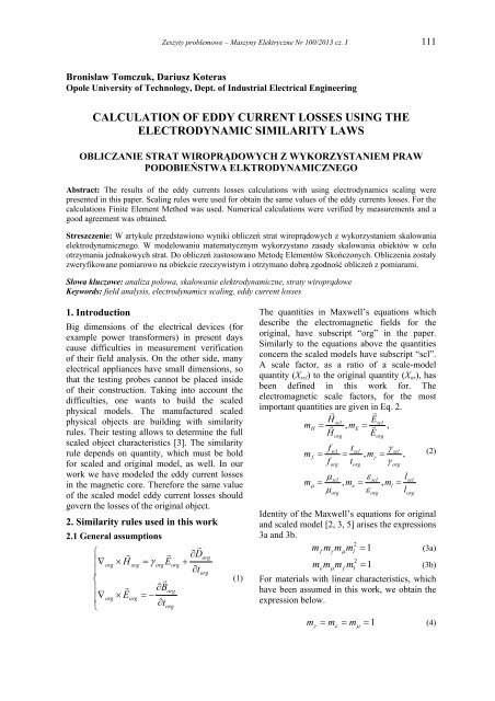
Zeszyty problemowe – Maszyny Elektryczne Nr 100/2013 cz. I 111Bronisław Tomczuk, Dariusz KoterasOpole University <strong>of</strong> Technology, Dept. <strong>of</strong> Industrial Electrical EngineeringCALCULATION OF EDDY CURRENT LOSSES USING THEELECTRODYNAMIC SIMILARITY LAWSOBLICZANIE STRAT WIROPRĄDOWYCH Z WYKORZYSTANIEM PRAWPODOBIEŃSTWA ELKTRODYNAMICZNEGOAbstract: The results <strong>of</strong> <strong>the</strong> <strong>eddy</strong> <strong>current</strong>s <strong>losses</strong> <strong>calculation</strong>s with <strong>using</strong> <strong>electrodynamic</strong>s scaling werepresented in this paper. Scaling rules were used for obtain <strong>the</strong> same values <strong>of</strong> <strong>the</strong> <strong>eddy</strong> <strong>current</strong>s <strong>losses</strong>. For <strong>the</strong><strong>calculation</strong>s Finite Element Method was used. Numerical <strong>calculation</strong>s were verified by measurements and agood agreement was obtained.Streszczenie: W artykule przedstawiono wyniki obliczeń strat wiroprądowych z wykorzystaniem skalowaniaelektrodynamicznego. W modelowaniu matematycznym wykorzystano zasady skalowania obiektów w celuotrzymania jednakowych strat. Do obliczeń zastosowano Metodę Elementów Skończonych. Obliczenia zostałyzweryfikowane pomiarowo na obiekcie rzeczywistym i otrzymano dobrą zgodność obliczeń z pomiarami.Słowa kluczowe: analiza polowa, skalowanie elektrodynamiczne, straty wiroprądoweKeywords: field analysis, <strong>electrodynamic</strong>s scaling, <strong>eddy</strong> <strong>current</strong> <strong>losses</strong>1. IntroductionBig dimensions <strong>of</strong> <strong>the</strong> electrical devices (forexample power transformers) in present dayscause difficulties in measurement verification<strong>of</strong> <strong>the</strong>ir field analysis. On <strong>the</strong> o<strong>the</strong>r side, manyelectrical appliances have small dimensions, sothat <strong>the</strong> testing probes cannot be placed inside<strong>of</strong> <strong>the</strong>ir construction. Taking into account <strong>the</strong>difficulties, one wants to build <strong>the</strong> scaledphysical models. The manufactured scaledphysical objects are building with similarityrules. Their testing allows to determine <strong>the</strong> fullscaled object characteristics [3]. The similarityrule depends on quantity, which must be holdfor scaled and original model, as well. In ourwork we have modeled <strong>the</strong> <strong>eddy</strong> <strong>current</strong> <strong>losses</strong>in <strong>the</strong> magnetic core. Therefore <strong>the</strong> same value<strong>of</strong> <strong>the</strong> scaled model <strong>eddy</strong> <strong>current</strong> <strong>losses</strong> shouldgovern <strong>the</strong> <strong>losses</strong> <strong>of</strong> <strong>the</strong> original object.2. Similarity rules used in this work2.1 General assumptions Dorgorg Horg orgEorgtorg Borgorg Eorg torg(1)The quantities in Maxwell’s equations whichdescribe <strong>the</strong> electromagnetic fields for <strong>the</strong>original, have subscript “org” in <strong>the</strong> paper.Similarly to <strong>the</strong> equations above <strong>the</strong> quantitiesconcern <strong>the</strong> scaled models have subscript “scl”.A scale factor, as a ratio <strong>of</strong> a scale-modelquantity (X scl ) to <strong>the</strong> original quantity (X or ), hasbeen defined in this work for. Theelectromagnetic scale factors, for <strong>the</strong> mostimportant quantities are given in Eq. 2.HEsclsclmH , mE ,H Emmfffsclorgorgsclorgtt, msclorg, msclorgorgsclorg,l, mllsclorg(2)Identity <strong>of</strong> <strong>the</strong> Maxwell’s equations for originaland scaled model [2, 3, 5] arises <strong>the</strong> expressions3a and 3b.m2 fm mm l1(3a)m m 2 m fm l1(3b)For materials with linear characteristics, whichhave been assumed in this work, we obtain <strong>the</strong>expression below.m m m 1(4)
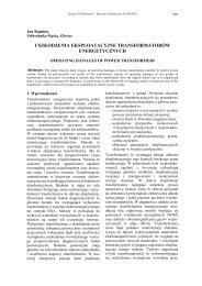
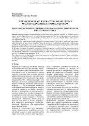
112 Zeszyty problemowe – Maszyny Elektryczne Nr 100/2013 cz. IThus, <strong>the</strong> magnetic field strength H <strong>current</strong> density J can be scaledmJmlmI 1m m mHHland <strong>the</strong>(5)2.2 The <strong>eddy</strong> <strong>current</strong> <strong>losses</strong> balanceLosses which are generating inside <strong>the</strong>conductors and magnetically s<strong>of</strong>t iron elementsinfluence heating <strong>of</strong> all electromagneticdevices. Thus, <strong>the</strong> computer aided design(CAD) should allow us to calculate <strong>the</strong> <strong>losses</strong> asexactly as possible. Using <strong>the</strong> field analysis, wehave computed <strong>the</strong> <strong>losses</strong> in original magneticcircuit, and inside its scaled duplicate. We havedetermined <strong>the</strong> similarity rules to define scaledobject <strong>eddy</strong> <strong>current</strong>s <strong>losses</strong>.In this paper <strong>the</strong> conductivity and magneticpermeability factors m =m =1 were assumed.Based on <strong>the</strong> expression (3a) <strong>the</strong> frequencyscale-factor can be given as m f =1/m 2 l . Thus, <strong>the</strong>relationship, between scale factors for magneticfield strength m H and geometric dimensions m l ,is equal to1mH (6)mlIn our ma<strong>the</strong>matical models we assumed <strong>the</strong>same number <strong>of</strong> turns N in <strong>the</strong> original andscaled model. Thus, <strong>the</strong> values <strong>of</strong> <strong>the</strong> excitation<strong>current</strong>s for scaled models is givenlaminated amorphous toroid which create a part<strong>of</strong> <strong>the</strong> magnetic leg. Due to <strong>the</strong> solid part, <strong>the</strong>magnetic flux density in all magnetic circuit isrelatively low. Thus, <strong>the</strong> circuit can be assumedas magnetically linear. We assumed <strong>the</strong> relativepermeability <strong>of</strong> <strong>the</strong> magnetic parts from <strong>the</strong>amorphous ribbon: r =20173 (for <strong>the</strong> yokes)and r =2067 (for <strong>the</strong> legs). Because <strong>the</strong> flux in<strong>the</strong> legs is perpendicular to wounding direction<strong>of</strong> <strong>the</strong> amorphous ribbon, <strong>the</strong> small permeabilityvalue is assumed. For <strong>the</strong> solid hollow cylinder,made from casting steel, <strong>the</strong> relativepermeability r =150 is assumed, and electricalconductivity =2.5·10 6 S/m have been included.a)Iscl m m I m I(7)Hlorglorg3. Analysed object and its ma<strong>the</strong>maticalmodel3.1 Analysed objectWe have studied <strong>the</strong> modular construction <strong>of</strong><strong>the</strong> amorphous, 1-phase transformer. Outlineand cross-section along YZ plane <strong>of</strong> <strong>the</strong>analysed object are presented in figures 1a) and1b). Moreover, in this figures <strong>the</strong> maindimensions and Cartesian system are given.Owing to modular construction <strong>of</strong> <strong>the</strong>amorphous transformer, we determined <strong>the</strong><strong>eddy</strong> <strong>current</strong> <strong>losses</strong> in <strong>the</strong> toroidal solidelement. It has been placed in <strong>the</strong> magneticcircuit as one part <strong>of</strong> its core. The core part wasmade from casting steel and situated in <strong>the</strong> rightside leg <strong>of</strong> <strong>the</strong> amorphous magnetic circuit (Fig.1b). Eddy <strong>current</strong> <strong>losses</strong> inside <strong>the</strong> solid toroidare several times higher than <strong>the</strong> ones inside <strong>the</strong>b)Fig. 1. Amorphous 1-phase transformer(original)a) Outline <strong>of</strong> <strong>the</strong> transformerb) Cross-section along YZ plane.
Zeszyty problemowe – Maszyny Elektryczne Nr 100/2013 cz. I 113The excitation winding has been wounded withN=116 turns and placed on <strong>the</strong> laminated (left)leg, Fig. 1b.3.2 Ma<strong>the</strong>matical modelFor numerical <strong>calculation</strong>s <strong>the</strong> Finite ElementMethod (FEM) has been implemented inmodule Elektra <strong>of</strong> <strong>the</strong> commercial packageOPERA 3D [1]. This module enables us toanalyse <strong>the</strong> electromagnetic fields taking intoaccount <strong>the</strong> effects <strong>of</strong> <strong>eddy</strong> <strong>current</strong>s. It can bedone <strong>using</strong> total A tand reduced A rmagneticvector potentials [1, 4]. B A t(8) B 0H S A r(9)In our ma<strong>the</strong>matical models, we assumedseveral values <strong>of</strong> rms values for <strong>the</strong> sinusoidalwaves <strong>of</strong> <strong>the</strong> excitation <strong>current</strong>: (1.42 to 9.50)A.The frequency <strong>of</strong> <strong>the</strong> supplying signal wasassumed to be f=50 Hz. Due to significant<strong>current</strong> <strong>losses</strong> inside <strong>the</strong> steel solid toroid <strong>the</strong><strong>losses</strong> in <strong>the</strong> amorphous parts, can be neglected.Moreover, in our <strong>calculation</strong>s we neglected <strong>the</strong><strong>losses</strong> appeared in <strong>the</strong> excitation coil. It can bepossible due to small cross section <strong>of</strong> its wires.4. Calculation results and measurementverificationIn this paper two variants <strong>of</strong> <strong>the</strong> field analysishave been carried out. The first variant W 1concerns <strong>the</strong> model two times smaller than <strong>the</strong>original object (m l =0.5). The second variant W 2relates to model which is two times bigger(m l =2) than <strong>the</strong> original. The assumedfrequency for W 1 variant was f scl =200 Hz. Thus,<strong>the</strong> scale factor for <strong>the</strong> frequency amounts m f =4.The rms values <strong>of</strong> <strong>the</strong> excitation <strong>current</strong>, has bechanged (I scl = 1.01÷6.74)A for consideredcases. In W 2 model <strong>the</strong> frequency f scl =12.5 Hzand its scale factor (m f =0.25) were arranged.Using Eq. 7 <strong>the</strong> rms <strong>current</strong> values forsinusoidal waves were changed from I scl = 2.0 toI scl = 13.3A, for <strong>the</strong> modeled objects.a)b)c)
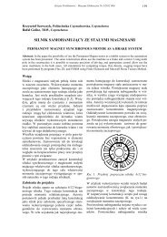
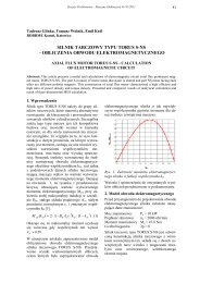
114 Zeszyty problemowe – Maszyny Elektryczne Nr 100/2013 cz. ICalculated values <strong>of</strong> <strong>the</strong> <strong>eddy</strong> <strong>current</strong> <strong>losses</strong> fordifferent excitations in both scaled variants andoriginal object are placed in <strong>the</strong> table 1.Table 1. Calculated values <strong>of</strong> <strong>the</strong> <strong>eddy</strong> <strong>current</strong><strong>losses</strong> inside <strong>the</strong> solid toroidI orgCalculationsm l =0.5 original m l =2[A] [W] [W] [W]1.42 5.44 5.85 6.003.06 24.90 27.29 28.005.25 73.05 80.07 82.167.23 138.40 151.70 155.669.50 239.2 262.56 269.42Fig. 2. Eddy <strong>current</strong> density distributions on <strong>the</strong>solid toroid surface and magnetic flux densityon plane YZ for excited <strong>current</strong> (originalobject) I org =5.25 Aa) original modelb) model with scaled factor m l =0.5c) model with scaled factor m l =2In figures 2a÷2c <strong>the</strong> <strong>eddy</strong> <strong>current</strong> densitiesdistributions on <strong>the</strong> surface <strong>of</strong> <strong>the</strong> casting steeli.e. solid toroid, for both original and scaled(two variants) numerical models, are presented.The <strong>calculation</strong>s have been carried out for rmsvalue <strong>of</strong> <strong>the</strong> excitation <strong>current</strong> I org =5.25 A. Thepresented distributions are similar to each o<strong>the</strong>r.Despite different dimensions and excitation<strong>current</strong> frequencies, <strong>the</strong> magnetic fields inside<strong>the</strong> analyzed magnetic circuits are notsignificantly different. For original object <strong>the</strong>maximal value <strong>of</strong> <strong>the</strong> <strong>eddy</strong> <strong>current</strong> density isslightly lower than 3 MA/m 2 , whereas for <strong>the</strong>scaled model with dimension factor m l =0.5(variant W 1 ) <strong>the</strong> maximum values reach almost8 MA/m 2 . In <strong>the</strong> case <strong>of</strong> two times bigger object(m l =2), this value is about 1.28 MA/m 2 .Eddy <strong>current</strong>s significantly influence <strong>the</strong> core<strong>losses</strong>, naturally. In this paper <strong>the</strong> <strong>losses</strong> <strong>of</strong> <strong>the</strong>solid steel toroid were calculated <strong>using</strong> <strong>the</strong>expression below2 J P eddV (10)V The relative differences between obtainedvalues for both scaled (variants W 1 and W 2 ) andoriginal models are lower than 10 %. Thus <strong>the</strong><strong>calculation</strong>s carried out in this work confirmcorrectness <strong>of</strong> <strong>the</strong> scaling rules. In Fig. 3 <strong>the</strong>calculated and measured values <strong>of</strong> <strong>the</strong> core<strong>losses</strong> inside <strong>of</strong> <strong>the</strong> solid toroid, for original andscaled objects, were given. As we can see, <strong>the</strong>presented values for <strong>the</strong> two objects come tonear.Fig. 3. The calculated and measured values <strong>of</strong><strong>the</strong> <strong>eddy</strong> <strong>current</strong> <strong>losses</strong> inside <strong>the</strong> solid toroidfor <strong>the</strong> original and scaled objects.5. ConclusionsIn this paper <strong>the</strong> <strong>eddy</strong> <strong>current</strong> <strong>losses</strong> inside <strong>the</strong>solid toroid, placed in <strong>the</strong> modular 1-phasemagnetic circuit from amorphous ribbon, werecalculated. The electromagnetic similarity ruleshave been analysed and used. The similarityrules were assumed to hold <strong>the</strong> same values <strong>of</strong><strong>the</strong> <strong>eddy</strong> <strong>current</strong> <strong>losses</strong>. Objects for two scaledfactors m l =0.5 and m l =2 have been modeled.
Zeszyty problemowe – Maszyny Elektryczne Nr 100/2013 cz. I 115Obtained values <strong>of</strong> <strong>the</strong> <strong>losses</strong> (table 1) confirm<strong>the</strong> correctness <strong>of</strong> <strong>the</strong> similarity rules. Thus, bycombining <strong>the</strong> scaled physical model and <strong>the</strong>ma<strong>the</strong>matical field problem solution, <strong>the</strong>designer can create, without expensiveprototyping, <strong>the</strong> accurate geometry <strong>of</strong> anelectromagnetic device.6. References[1] OPERA Manager User Guide Version 13,Cobham Technical Services, Oxford, England,2009.[2] Zakrzewski K., Tomczuk B., Waindok A.,Nonlinear scaled models in 3-d <strong>calculation</strong> <strong>of</strong>transformer magnetic circuits, XVIIISymposium Electromagnetic Phenomena inNonlinear Circuits, Poznan, Poland, 28-30 VI,2004, pp. 31-32.[3] Turowski J., Elektrodynamika Techniczna, WNTWarszawa 1993r.[4] Xu E.X., Simkin J., Total/Reduced magneticvector potential and electrical scalar potentialfor <strong>eddy</strong> <strong>current</strong> <strong>calculation</strong>, Compumag’03,Saratoga Springs, 13-17 VII 2003, pp. I / 8 – 9.[5] Zakrzewski K., Modelowanie pólelektromagnetycznych w projektowaniutransformatorów, Przegląd Elektrotechniczny, nr3, 2002, s. 59-63.D. Koteras was born in Swidnica, Poland in1972. He received <strong>the</strong> MS and PhD degrees inElectrical Engineering from Opole University<strong>of</strong> Technology in 1998 and 2006, respectively.Since 1998, he has been employed at <strong>the</strong>university. Presently, he is an adjunct.ReviewerPr<strong>of</strong>. dr hab. inż. Wojciech Szeląg7. AcknowledgementsThis paper is partially supported by <strong>the</strong>National Science Centre under grant no. NN510 533739.8. AuthorsPr<strong>of</strong>. Bronislaw Tomczuk, (Ph.D., D.Sc.),Department <strong>of</strong> Electrical Engineering, OpoleUniversity <strong>of</strong> Technology, ul. Proszkowska 76,45-758 Opole.PhD Eng. Dariusz Koteras, as above.B. Tomczuk was born in Poland in 1953. Hereceived his PhD and DSc degrees from <strong>the</strong>Technical University <strong>of</strong> Lodz (Poland) in 1985and 1995, respectively. Prior to that, hereceived <strong>the</strong> MSc degree in ElectricalEngineering with honours in 1977. Since 1978,he has been on <strong>the</strong> staff <strong>of</strong> <strong>the</strong> TechnicalUniversity <strong>of</strong> Opole, Poland. From 1996, he hasbeen within <strong>the</strong> pr<strong>of</strong>essor staff <strong>of</strong> Faculty <strong>of</strong>Electrical Engineering, Automatic Control andInformatics. He obtained his full pr<strong>of</strong>essor titlein 2007. At present, he is <strong>the</strong> Head <strong>of</strong> <strong>the</strong>Department <strong>of</strong> Industrial Electrical Engineeringat <strong>the</strong> Opole University <strong>of</strong> Technology.
116 Zeszyty problemowe – Maszyny Elektryczne Nr 100/2013 cz. I