Optimal Engine Design Using Nonlinear Programming and the ...
Optimal Engine Design Using Nonlinear Programming and the ...
Optimal Engine Design Using Nonlinear Programming and the ...

Create successful ePaper yourself
Turn your PDF publications into a flip-book with our unique Google optimized e-Paper software.
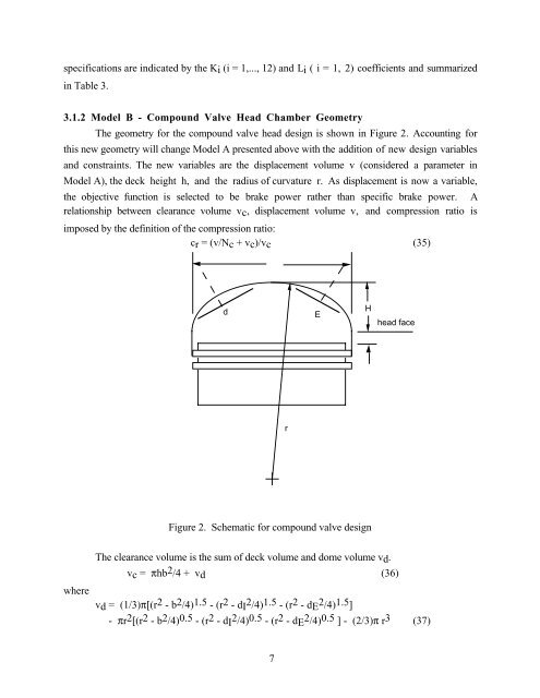
specifications are indicated by <strong>the</strong> Ki (i = 1,..., 12) <strong>and</strong> Li ( i = 1, 2) coefficients <strong>and</strong> summarizedin Table 3.3.1.2 Model B - Compound Valve Head Chamber GeometryThe geometry for <strong>the</strong> compound valve head design is shown in Figure 2. Accounting forthis new geometry will change Model A presented above with <strong>the</strong> addition of new design variables<strong>and</strong> constraints. The new variables are <strong>the</strong> displacement volume v (considered a parameter inModel A), <strong>the</strong> deck height h, <strong>and</strong> <strong>the</strong> radius of curvature r. As displacement is now a variable,<strong>the</strong> objective function is selected to be brake power ra<strong>the</strong>r than specific brake power. Arelationship between clearance volume vc, displacement volume v, <strong>and</strong> compression ratio isimposed by <strong>the</strong> definition of <strong>the</strong> compression ratio:cr = (v/Nc + vc)/vc (35)dEHhead facerFigure 2. Schematic for compound valve designwhereThe clearance volume is <strong>the</strong> sum of deck volume <strong>and</strong> dome volume vd.vc = πhb 2 /4 + vd (36)vd = (1/3)π[(r 2 - b 2 /4) 1.5 - (r 2 - dI 2 /4) 1.5 - (r 2 - dE 2 /4) 1.5 ]- πr 2 [(r 2 - b 2 /4) 0.5 - (r 2 - dI 2 /4) 0.5 - (r 2 - dE 2 /4) 0.5 ] - (2/3)π r 3 (37)7