INSTRUCTION MANUAL FOR PLASMA CUTTER - Cebotechusa.com
INSTRUCTION MANUAL FOR PLASMA CUTTER - Cebotechusa.com
INSTRUCTION MANUAL FOR PLASMA CUTTER - Cebotechusa.com

You also want an ePaper? Increase the reach of your titles
YUMPU automatically turns print PDFs into web optimized ePapers that Google loves.
<strong>INSTRUCTION</strong> <strong>MANUAL</strong> <strong>FOR</strong> <strong>PLASMA</strong> <strong>CUTTER</strong><br />
IMPORTANT: BE<strong>FOR</strong>E STARTING THE<br />
EQUIPMENT, READ THE CONTENTS<br />
OF THIS <strong>MANUAL</strong>, WHICH MUST BE<br />
STORED IN A PLACE FAMILIAR TO ALL USERS <strong>FOR</strong> THE<br />
ENTIRE OPERATIVE LIFE-SPAN OF THE MACHINE.<br />
THIS EQUIPMENT MUST BE USED SOLELY <strong>FOR</strong> WEL-<br />
DING OPERATIONS.<br />
1 SAFETY PRECAUTIONS<br />
WELDING AND ARC CUTTING CAN BE HARMFUL TO<br />
YOURSELF AND OTHERS.The user must therefore be educated<br />
against the hazards, summarized below, deriving from<br />
welding operations. For more detailed information, order the<br />
manual code 3.300.758<br />
ELECTRIC SHOCK - May be fatal.<br />
· Install and earth the welding machine according to<br />
the applicable regulations.<br />
· Do not touch live electrical parts or electrodes with<br />
bare skin, gloves or wet clothing.<br />
· Isolate yourselves from both the earth and the workpiece.<br />
· Make sure your working position is safe.<br />
FUMES AND GASES - May be hazardous to your health.<br />
· Keep your head away from fumes.<br />
· Work in the presence of adequate ventilation, and<br />
use ventilators around the arc to prevent gases from<br />
forming in the work area.<br />
ARC RAYS - May injure the eyes and burn the skin.<br />
· Protect your eyes with welding masks fitted with filtered<br />
lenses, and protect your body with appropriate<br />
safety garments.<br />
· Protect others by installing adequate shields or curtains.<br />
RISK OF FIRE AND BURNS<br />
· Sparks (sprays) may cause fires and burn the skin;<br />
you should therefore make sure there are no flammable<br />
materials in the area, and wear appropriate<br />
protective garments.<br />
NOISE<br />
This machine does not directly produce noise exceeding<br />
80dB. The plasma cutting/welding procedure<br />
may produce noise levels beyond said limit; users<br />
must therefore implement all precautions required by law.<br />
PACEMAKERS<br />
· The magnetic fields created by high currents may affect the<br />
operation of pacemakers. Wearers of vital electronic equipment<br />
(pacemakers) should consult their physician before<br />
beginning any arc welding, cutting, gouging or spot welding<br />
operations.<br />
EXPLOSIONS<br />
· Do not weld in the vicinity of containers under pressure,<br />
or in the presence of explosive dust, gases or<br />
fumes. · All cylinders and pressure regulators used in<br />
welding operations should be handled with care.<br />
ELECTROMAGNETIC COMPATIBILITY<br />
This machine is manufactured in <strong>com</strong>pliance with the instruc-<br />
6<br />
tions contained in the harmonized standard EN50199, and<br />
must be used solely for professional purposes in an<br />
industrial environment. There may be potential difficulties<br />
in ensuring electromagnetic <strong>com</strong>patibility in nonindustrial<br />
environments.<br />
IN CASE OF MALFUNCTIONS, REQUEST ASSISTANCE<br />
FROM QUALIFIED PERSONNEL.<br />
2 GENERAL DESCRIPTION<br />
This machine is a constant direct current power source,<br />
designed for cutting electrically conductive materials<br />
(metals and alloys) using the plasma arc procedure. The<br />
plasma gas may be air or nitrogen.<br />
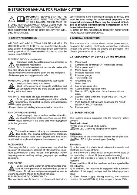
2.1 DESCRIPTION OF DEVICES ON THE MACHINE<br />
A) Power cord<br />
B) Compressed air fitting (1/4" female gas thread)<br />
C) Mains power switch<br />
D) Mains power led<br />
E) Pressure regulator knob<br />
F) Pressure gauge<br />
G) Thermostat LED<br />
H) Grounding cord<br />
I) Water trap<br />
L) Low air pressure LED<br />
M) Cutting current regulator knob<br />
N) Blocked LED; lights when hazardous conditions<br />
arise.<br />
O) LED that lights when the "SELF-RESTART PILOT"<br />
function is active<br />
P) Push-button to activate and deactivate the "SELF-<br />
RESTART PILOT" function.<br />
O) Plasma torch.<br />
2.2 SAFETY DEVICES<br />
This system <strong>com</strong>es equipped with the following safety<br />
devices:<br />
Overload cutout:<br />
To avoid overload while cutting.<br />
The LED G (see fig 1) lights when active.<br />
Pneumatic:<br />
Located on the torch inlet to prevent low air pressure.<br />
The LED L lights when tripped (see fig.1).<br />
➡➡<br />
Electrical:<br />
1) In the event of a short-circuit between the nozzle and<br />
electrode during arc striking<br />
2) In the event of a short-circuit between the contacts of<br />
the reed relay on circuit 22 (see exploded drawing).<br />
3) When the electrode is worn to the point it must be<br />
replaced.<br />
These conditions block the machine, and are signalled by<br />
the lit LED N.<br />
4) In addition, this machine is equipped with automatic<br />
selection of the supply voltage and the following protections:<br />
A) 230V Power supply: during start-up, the machine<br />
remains blocked (LED N lit) if the voltage is below 200V.
M<br />
G<br />
N<br />
D<br />
L<br />
O<br />
P<br />
Q<br />
H<br />
E<br />
F<br />
B<br />
C<br />
A<br />
I<br />
��<br />
SELF-<br />
RESTART<br />
PILOT<br />
®<br />
INVERTER INVERTER<br />
19 20 21<br />
18<br />
22<br />
17<br />
23<br />
16<br />
15<br />
A<br />
24<br />
25<br />
Art.296<br />
POWER <strong>PLASMA</strong> <strong>PLASMA</strong> 3100<br />
V<br />
Fig.1<br />
S<br />
I<br />
0<br />
®<br />
Via A.Costa, 24<br />
40057-Cadriano-Bologna-Italy<br />
After start-up, the machine runs at as low as 180V.<br />
B) 115V Power supply: during start-up, the machine<br />
remains blocked (LED N lit) if the voltage is below 100V.<br />
After start-up, the machine runs at as low as 90V.<br />
Do not remove or short-circuit the safety devices.<br />
Use only original spare parts.<br />
Always replace any damaged parts of the machine<br />
with original materials.<br />
Use only CEBORA torches type CP40.<br />
Do not run the machine without its housings. This<br />
would be dangerous to the operator and anyone else<br />
in the work area, and would prevent the machine from<br />
being cooled properly.<br />
2.3 EXPLANATION OF TECHNICAL SPECIFICATIONS<br />
EN 60974.1 The machine has been built according to<br />
EN 50199 this European standards.<br />
EN 50192<br />
N°..................... Serial number.<br />
Always indicate this for any request regar<br />
ding the machine.<br />
....... Single-phase static transformer-rectifier<br />
frequency converter.<br />
................... Drooping characteristic.<br />
.................Suitable for plasma cutting.<br />
TORCH TYPE........Type of torch that may be used with this<br />
machine.<br />
U 0. PEAK........Secondary open-circuit voltage. Peak<br />
value.<br />
X....................... Percentage duty cycle.<br />
The duty cycle expresses the percentage<br />
of 10 minutes for which the machine may<br />
work at a certain current I 2 and voltage<br />
U 2 without overheating.<br />
I 2....................... Cutting current.<br />
U 2..................... Secondary voltage at cutting current I 2.<br />
This voltage is measured when cutting<br />
with the gas nozzle in contact with the<br />
workpiece.<br />
If this distance increases, the cutting<br />
voltage also increases and the duty<br />
cycle X% may drop.<br />
U 1......................Rated supply voltage<br />
1~ 50/60Hz....... 50- or 60-Hz single-phase power supply.<br />
The machine is equipped with automatic<br />
voltage change.<br />
I 1....................... at the corresponding<br />
cutting current I 2 and voltage U 2.<br />
IP23.................. Housing protection rating.<br />
Class 3 as the second digit means that<br />
this machine is suitable for working out<br />
S<br />
doors in the rain.<br />
.................... Suitable for working in hazardous environments.<br />
NOTE: The machine has also been designed for use in<br />
environments with a pollution rating of 3. (See IEC 664).<br />
2.4 START-UP<br />
The machine must be installed by qualified personnel.<br />
All connections must be made in <strong>com</strong>pliance with cur-<br />
7
ent safety standards and full observance of safety<br />
regulations (see CEI 26-10 CENELEC HD427).<br />
Connect the air supply to the fitting B.<br />
If the system air contains a considerable amount of moisture<br />
and oil, it is best to use a drying filter to avoid excessive<br />
oxidation and wear of the consumer parts, damaging<br />
the torch and reducing the cutting speed and quality.<br />
If the air supply <strong>com</strong>es from a pressure regulator of a <strong>com</strong>pressor<br />
or centralized system, the regulator must be set to<br />
an output pressure of no more than 8 bar (0.8 Mpa). If the<br />
air supply <strong>com</strong>es from a <strong>com</strong>pressed air cylinder, the<br />
cylinder must be equipped with a pressure regulator.<br />
Never connect a <strong>com</strong>pressed air cylinder directly to<br />
the regulator on the machine! The pressure could<br />
exceed the capacity of the regulator, which might<br />
explode!<br />
Connect the power cord A : the yellow-green cable wire<br />
must be connected to an efficient grounding socket on the<br />
system. The remaining wires must be connected to the<br />
power supply line by means of a switch placed as close as<br />
possible to the cutting area, to allow it to be shut off quickly<br />
in case of emergency.<br />
The capacity of the cut-out switch or fuses installed in<br />
series with the switch must be equal to the current I 1<br />
absorbed by the machine.<br />
The absorbed current I 1 may be determined by reading<br />
the technical specifications shown on the machine under<br />
the available supply voltage U 1.<br />
Any extension cords must be sized appropriately for the<br />
absorbed current I 1.<br />
3 USE<br />
Read the standards CEI 26/9 - CENELEC HD 407 and CEI<br />
26.11 - CENELEC HD 433 carefully before using the<br />
equipment, and make sure the cable insulation is fully<br />
intact. Make sure the trigger has not been pressed.<br />
Turn the machine on using the switch C. The warning<br />
lamp D will light to indicate that the machine is on.<br />
Press the torch trigger briefly to open the flow of <strong>com</strong>pressed<br />
air. Since the arc is not lit, air leaves the torch for<br />
only 5 sec. Now adjust the pressure, shown on the pressure<br />
gauge F, to 3.5 bar (0.35 MPA) using the knob E on<br />
the regulator, then lock the knob by pressing it downward.<br />
Connect the grounding clamp to the workpiece.<br />
The cutting circuit must not be deliberately placed in direct<br />
or indirect contact with the protective wire except in the<br />
workpiece.<br />
If the workpiece is deliberately grounded using the protective<br />
conductor, the connection must be as direct as possible<br />
and use a wire of at least the same size as the cutting<br />
current return wire, and connected to the workpiece at the<br />
same point as the return wire using the return wire clamp<br />
or a second grounding clamp placed in the immediate vicinity.<br />
Every precaution must be taken to avoid stray currents.<br />
Use the knob M to select the cutting current.<br />
Make sure that the grounding clamp and workpiece have<br />
a good electrical contact, especially with painted, oxidized<br />
or insulated sheet metal.<br />
Do not connect the grounding clamp to the part of the<br />
material that is to be removed.<br />
Press the torch trigger to strike the pilot arc.<br />
If cutting does not begin within 2 seconds, the pilot arc<br />
8<br />
fig.2/A fig. 2/B<br />
goes out; press the trigger again to re-strike it.<br />
Begin cutting as shown in fig. 2a, avoid starting as shown<br />
in fig. 2b<br />
Hold the torch upright while cutting.<br />
When you have finished cutting and released the trigger,<br />
air will continue to leave the torch for approximately 40<br />
seconds to allow the torch to cool down.<br />
It is best not to turn the machine off until this cooldown<br />
period is <strong>com</strong>plete.<br />
To cut perforated or grid metal, activate the "Pilot self<br />
restart" function using the push-button P (LED O lit).<br />
When you have finished cutting, holding this push-button<br />
down will cause the pilot arc to restart automatically.<br />
Use this function only if necessary to avoid unnecessary<br />
wear on the electrode and nozzle.<br />
Should you need to make holes or begin cutting from the<br />
center of the workpiece, you must hold the torch at an<br />
angle and slowly straighten it so that the nozzle does not<br />
spray molten metal (see fig. 3). This must be done when<br />
making holes in pieces more than 3 mm thick.<br />
Turn the machine off when the task is <strong>com</strong>pleted.<br />
fig.3 fig. 4<br />
3.1 REPLACING CONSUMER PARTS<br />
Always shut off the machine before replacing consumer<br />
parts.<br />
The electrode must be replaced when it has a crater in<br />
the center approximately 1 mm deep.<br />
The gas nozzle must be replaced when the hole is no<br />
longer smooth and the cutting capacity is diminished.<br />
The diffuser must be replaced when some areas are<br />
blackened. Due to its small size, it is very important to<br />
position it correctly during assembly (see fig. 4).<br />
o The nozzle holder must be replaced when the
insulating part is deteriorated<br />
Make sure that the electrode T, the diffuser U and the<br />
gas nozzle V are mounted correctly, and that the nozzle<br />
holder W is firmly tightened.<br />
If any of these parts are missing, this will interfere<br />
with smooth operation of the machine and, especially,<br />
jeopardize operator safety<br />
4 CUTTING ERRORS<br />
4.1 INSUFFICIENT PENETRATION<br />
This error may be caused by the following:<br />
high speed. Always make sure that the arc fully penetrates<br />
the workpiece and is never held at a forward angle<br />
of more than 10 -15°. This will avoid incorrect consumption<br />
of the nozzle and burns to the nozzle holder.<br />
Excessively thick workpiece (see cutting speed diagrams,<br />
fig. 5).<br />
Fig. 5<br />
Grounding clamp not in good electrical contact with the<br />
workpiece.<br />
Worn nozzle and electrode.<br />
Cutting current too low.<br />
NOTE: When the arc does not penetrate, the molten metal<br />
scraps obstruct the nozzle.<br />
4.2 THE CUTTING ARC GOES OFF<br />
This error may be caused by:<br />
worn nozzle, electrode or swirl ring.<br />
air pressure too high.<br />
supply voltage too low.<br />
4.3 SHORTER LIFE OF CONSUMER PARTS<br />
This error may be caused by:<br />
oil or dirt in the arc intake,<br />
unnecessarily long pilot arc,<br />
low arc pressure.<br />
5 HELPFUL HINTS<br />
If the system air contains considerable amounts of moisture<br />
and oil, it is best to use a drying filter to avoid excessive<br />
oxidation and wear on consumer parts, damage to<br />
the torch and a reduction in the speed and quality of the<br />
cutting.<br />
Make sure that the new electrode and nozzle to be<br />
mounted are thoroughly clean and degreased.<br />
Always use original spare parts to avoid damaging<br />
the torch.<br />
6 MAINTENANCE<br />
Always cut off the power supply to the machine before any<br />
operation, which must always be carried out by qualified<br />
personnel.<br />
6.1 GENERATOR MAINTENANCE<br />
In the case of maintenance inside the machine, make sure<br />
that the switch C is in position "O" and that the power<br />
cord is disconnected from the mains.<br />
Even though the machine is equipped with an automatic<br />
condensation drainage device that is tripped each time the<br />
air supply is closed, it is good practice to periodically make<br />
sure that there is no condensation accumulated in the<br />
water trap I (fig.1).<br />
It is also necessary to periodically clean the interior of the<br />
machine from the accumulated metal dust, using <strong>com</strong>pressed<br />
air.<br />
6.2 PRECAUTIONS AFTER REPAIRS.<br />
After making repairs, take care to organize the wiring so that<br />
there is secure insulation between the primary and secondary<br />
sides of the machine. In particular, make sure that the<br />
casing 50 is mounted (see exploded drawing). Do not allow<br />
the wires to <strong>com</strong>e into contact with moving parts or those that<br />
heat up during operation. Reassemble all clamps as they<br />
were on the original machine, to prevent a connection from<br />
occurring between the primary and secondary circuits should<br />
a wire accidentally break or be disconnected.<br />
Also mount the screws with geared washers as on the original<br />
machine.<br />
9