instruction manual for wire welding machine - Cebotechusa.com
instruction manual for wire welding machine - Cebotechusa.com
instruction manual for wire welding machine - Cebotechusa.com

You also want an ePaper? Increase the reach of your titles
YUMPU automatically turns print PDFs into web optimized ePapers that Google loves.
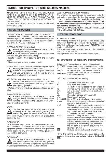
INSTRUCTION MANUAL FOR WIRE WELDING MACHINE<br />
IMPORTANT: BEFORE STARTING THE EQUIPMENT,<br />
READ THE CONTENTS OF THIS MANUAL, WHICH<br />
MUST BE STORED IN A PLACE FAMILIAR TO ALL<br />
USERS FOR THE ENTIRE OPERATIVE LIFE-SPAN OF<br />
THE MACHINE.<br />
THIS EQUIPMENT MUST BE USED SOLELY FOR WELD-<br />
ING OPERATIONS.<br />
1 SAFETY PRECAUTIONS<br />
WELDING AND ARC CUTTING CAN BE HARMFUL TO<br />
YOURSELF AND OTHERS. The user must there<strong>for</strong>e be<br />
educated against the hazards, summarized below, deriving<br />
from <strong>welding</strong> operations. For more detailed in<strong>for</strong>mation,<br />
order the <strong>manual</strong> code 3.300.758<br />
ELECTRIC SHOCK - May be fatal.<br />
• Install and earth the <strong>welding</strong> <strong>machine</strong> according<br />
to the applicable regulations.<br />
• Do not touch live electrical parts or electrodes<br />
with bare skin, gloves or wet clothing.<br />
• Isolate yourselves from both the earth and the workpiece.<br />
• Make sure your working position is safe.<br />
FUMES AND GASES - May be hazardous to your health.<br />
• Keep your head away from fumes.<br />
• Work in the presence of adequate ventilation,<br />
and use ventilators around the arc to prevent<br />
gases from <strong>for</strong>ming in the work area.<br />
ARC RAYS - May injure the eyes and burn the skin.<br />
• Protect your eyes with <strong>welding</strong> masks fitted with<br />
filtered lenses, and protect your body with appropriate<br />
safety garments.<br />
• Protect others by installing adequate shields or curtains.<br />
RISK OF FIRE AND BURNS<br />
• Sparks (sprays) may cause fires and burn the<br />
skin; you should there<strong>for</strong>e make sure there are no<br />
flammable materials in the area, and wear appropriate<br />
protective garments.<br />
NOISE<br />
This <strong>machine</strong> does not directly produce noise<br />
exceeding 80dB. The plasma cutting/<strong>welding</strong> procedure<br />
may produce noise levels beyond said<br />
limit; users must there<strong>for</strong>e implement all precautions<br />
required by law.<br />
PACEMAKERS<br />
• The magnetic fields created by high currents may affect<br />
the operation of pacemakers. Wearers of vital electronic<br />
equipment (pacemakers) should consult their physician<br />
be<strong>for</strong>e beginning any arc <strong>welding</strong>, cutting, gouging or<br />
spot <strong>welding</strong> operations.<br />
EXPLOSIONS<br />
• Do not weld in the vicinity of containers under pressure,<br />
or in the presence of explosive dust, gases or<br />
fumes. • All cylinders and pressure regulators used<br />
in <strong>welding</strong> operations should be handled with care.<br />
ELECTROMAGNETIC COMPATIBILITY<br />
This <strong>machine</strong> is manufactured in <strong>com</strong>pliance with the<br />
<strong>instruction</strong>s contained in the harmonized standard<br />
EN50199, and must be used solely <strong>for</strong> professional purposes<br />
in an industrial environment. There may be potential<br />
difficulties in ensuring electromagnetic <strong>com</strong>patibility in<br />
non-industrial environments.<br />
IN CASE OF MALFUNCTIONS, REQUEST ASSISTANCE<br />
FROM QUALIFIED PERSONNEL.<br />
2 GENERAL DESCRIPTIONS<br />
2.1 SPECIFICATIONS<br />
This <strong>welding</strong> <strong>machine</strong> is a power source made using<br />
INVERTER technology, suitable <strong>for</strong> synergic pulsed<br />
MIG/MAG <strong>welding</strong>, non-pulsed synergic MIG/MAG, conventional<br />
MIG/MAG.<br />
The equipment may be used only <strong>for</strong> the purposes<br />
described in the <strong>manual</strong>.<br />
The equipment must not be used to defrost pipes.<br />
2.2 EXPLANATION OF TECHNICAL SPECIFICATIONS<br />
IEC 60974.1 The <strong>welding</strong> <strong>machine</strong> is manufactured<br />
EN 50199 according to these international standards<br />
N°. Serial number. Must be indicated on any<br />
type of request regarding the <strong>welding</strong> <strong>machine</strong>.<br />
1~ f1<br />
f 2<br />
single-phase static frequency converter<br />
trans<strong>for</strong>mer-rectifier.<br />
MIG Suitable <strong>for</strong> MIG <strong>welding</strong>.<br />
U0. Secondary open-circuit voltage.<br />
X. Duty cycle percentage<br />
The duty cycle expresses the percentage of<br />
10 minutes during which the <strong>welding</strong> <strong>machine</strong><br />
may run at a certain current without overheating.<br />
I2. Welding current<br />
U2. Secondary voltage with current I2<br />
U1. Rated supply voltage<br />
1~ 50/60Hz 50- or 60-Hz single-phase power supply<br />
I1 Max Max. absorbed current at the corresponding<br />
current I2 and voltage U2. I1 eff This is the maximum value of the actual curent<br />
absorbed, considering the duty cycle.<br />
This value usually corresponds to the capacity<br />
of the fuse (delayed type) to be used as<br />
a protection <strong>for</strong> the equipment.<br />
IP23 C. Protection rating <strong>for</strong> the housing.<br />
Grade 3 as the second digit means that this<br />
equipment is suitable <strong>for</strong> use outdoors in the<br />
rain.The additional letter C means that the<br />
equipment is protected against access to<br />
the live parts of the power circuit by a tool<br />
(diameter 2.5 mm ).<br />
S Suitable <strong>for</strong> use in high-risk environments.<br />
NOTE: The <strong>welding</strong> <strong>machine</strong> has also been designed <strong>for</strong><br />
use in environments with a pollution rating of 3. (See IEC<br />
664).<br />
9
2.3 PROTECTIONS<br />
2.3.1 Block protection<br />
In the event of a malfunction, a number with the following<br />
meaning may appear on the display G:<br />
52 = Start button pressed during start-up.<br />
53 = start button pressed during thermostat reset.<br />
56 = Extended short-circuit between the <strong>welding</strong><br />
electrode and the material to be welded.<br />
Shut the <strong>machine</strong> off and turn it back on.<br />
If different numbers appear on the display, contact technical<br />
service.<br />
2.3.2 Mechanical protection (safety button)<br />
When the movable side is opened, this activates the safety<br />
button which prevents operation of the <strong>welding</strong><br />
<strong>machine</strong>. This protection, indicated when the flashing<br />
message "OPn" appears on display G, avoids hazardous<br />
situations when the operator replaces the roller of the<br />
<strong>wire</strong> feeder unit or the <strong>welding</strong> electrode.<br />
2.3.3 Thermal protection<br />
This <strong>machine</strong> is protected by a thermostat, which prevents<br />
the <strong>machine</strong> from operating if the allowable temperatures are<br />
exceeded. In these conditions the fan continues to operate<br />
and the display G flashes the abbreviation "OPn".<br />
10<br />
®<br />
INVERTER<br />
MIG<br />
MIG MIG 2035/M 2035/M<br />
PULSE Art.285<br />
3 INSTALLATION<br />
Make sure that the supply voltage matches the voltage<br />
indicated on the specifications plate of the <strong>welding</strong><br />
<strong>machine</strong>.<br />
Mount a plug with an adequate capacity <strong>for</strong> the supply<br />
cable, making sure that the yellow/green conductor is<br />
connected to the earth pin.<br />
The capacity of the overload cutout switch or fuses<br />
installed in series with the power supply must be equivalent<br />
to the absorbed current I1 of the <strong>machine</strong>.<br />
3.1 START-UP<br />
The <strong>machine</strong> must be installed by skilled personnel. All<br />
connections must be carried out according to current<br />
regulations, and in full observance of safety laws (regulation<br />
CEI 26-10 - CENELEC HD 427)<br />
3.2 CONTROLS ON THE FRONT PANEL.<br />
A- Yellow Hold LED<br />
Signals that the current shown on display G is the one<br />
actually used in <strong>welding</strong>. Activated at the end of each<br />
<strong>welding</strong> session.<br />
A H<br />
B<br />
C<br />
D<br />
E<br />
F<br />
HOLD<br />
5 6<br />
4 7<br />
3<br />
8<br />
2<br />
9<br />
1<br />
10<br />
888<br />
A<br />
SINERGIC<br />
5 6<br />
4 7<br />
3<br />
8<br />
2<br />
9<br />
1<br />
10<br />
V<br />
5 6 5 6<br />
4 7 4 7<br />
MIG<br />
PULSE<br />
3 8 3<br />
8<br />
2 9 2<br />
9<br />
1 10 1 10<br />
88<br />
P<br />
1<br />
2<br />
3<br />
4<br />
5<br />
0 1<br />
2<br />
3<br />
4<br />
5<br />
G<br />
I<br />
L<br />
M<br />
N<br />
O<br />
P<br />
Q<br />
R<br />
S<br />
Fig. 1
B- Wire speed adjustment knob.<br />
By adjusting this knob:<br />
• when conventional programs are used, the display G<br />
shows the speed in meters per minute.<br />
• when synergic programs are used (pulsed or conventional),<br />
the display G shows the current at which <strong>welding</strong><br />
will take place.<br />
• when pulsed synergic programs are used, the display Q<br />
shows, <strong>for</strong> approximately 2 seconds, the re<strong>com</strong>mended<br />
thickness <strong>for</strong> the current being set; after which it returns<br />
to displaying the number of the selected <strong>welding</strong> program.<br />
C - Green LED.<br />
Signals activation of the spot or dash <strong>welding</strong> mode when<br />
lit together with LED M.<br />
D - Setting knob.<br />
This knob adjusts the spot <strong>welding</strong> or working time during<br />
dash <strong>welding</strong>.<br />
E - Central adapter<br />
This is where the <strong>welding</strong> torch is to be connected.<br />
F - Earth socket<br />
Grounding cable socket.<br />
G - 3-digit display<br />
This display shows:<br />
• when selecting synergic programs (button R), the type<br />
of material corresponding to the program selected (FE =<br />
Iron, AL = Aluminium, SS = Stainless steel).<br />
• in conventional programs, be<strong>for</strong>e <strong>welding</strong>, the <strong>wire</strong><br />
speed and current after <strong>welding</strong>.<br />
• in synergic programs, be<strong>for</strong>e <strong>welding</strong>, the speed or preset<br />
current, and after <strong>welding</strong> the actual current used.<br />
• in conventional and pulsed or conventional synergic<br />
programs, the variations in arc length (knob I) and variations<br />
in impedance (knob P) from the re<strong>com</strong>mended zero<br />
position.<br />
• the abbreviation "OPn" (flashing) if the motor <strong>com</strong>partment<br />
door is opened.<br />
• the message "OPn" (flashing) if the thermostat is<br />
tripped.<br />
• in the service functions (see chapter 5 <strong>for</strong> further clarification)<br />
displays the messages: dSP, Job, PrF, PoF, Acc,<br />
bb, HSA, SC, Len, Slo, 3L, CrC, 2-4.<br />
• in the memory menu the letter P followed by two digits<br />
representing the memory number. Read chapter 6 <strong>for</strong> further<br />
clarification.<br />
H - Green LED.<br />
Signals that the program used <strong>for</strong> <strong>welding</strong> is pulsed synergic.<br />
I - Setting knob.<br />
Adjusts the <strong>welding</strong> voltage in conventional programs.<br />
Range from 1 to 10<br />
In synergic and pulsed synergic programs, the indicator<br />
of this knob must be set to the "SYNERGIC " symbol in<br />
the center of the setting range; this symbol represents the<br />
setting re<strong>com</strong>mended by the manufacturer. Adjusting this<br />
knob allows you to correct the arc length value. Changes<br />
to this figure, greater than or less than the "SYNERGIC"<br />
setting, are shown on the display G, which will show the<br />
previous size 2 seconds after the last correction.<br />
L - Green LED.<br />
Indicates that continuous <strong>welding</strong> mode is activated.<br />
M - Green LED.<br />
Indicates that dash <strong>welding</strong> mode is activated. It lights<br />
together with LED C.<br />
N - Setting knob.<br />
This knob adjusts the pause time between spot welds.<br />
O - Key.<br />
Pressing and releasing this key increases the numerical<br />
value of the display Q.<br />
When pressed together with the key R, allows selection of<br />
the service and memory functions and saves programs.<br />
(See chapter 6)<br />
P- Setting knob.<br />
In conventional programs adjustment from 1 to 10<br />
This knob adjusts the impedance value.<br />
For each synergic program, the optimum value is position<br />
0. The <strong>machine</strong> automatically sets the correct impedance<br />
value based on the program selected. The operator may<br />
correct the set value: adjusting the potentiometer<br />
towards + will produce warmer, less penetrating welds,<br />
while vice-versa adjusting towards - will produce colder<br />
and more penetrating welds<br />
When <strong>welding</strong> with a synergic program, adjusting + or -<br />
from the central 0 may require corrections to the working<br />
voltage using the potentiometer I.<br />
The variation is shown on the display G, which shows the<br />
previous setting 2 seconds after the last correction.<br />
Q - 2-digit display.<br />
This display shows:<br />
• the number of the selected program.<br />
• <strong>for</strong> 2 seconds, the value of the thickness when knob B<br />
is adjusted in pulsed synergic programs.<br />
• within the service functions, the numerical value of the<br />
figure shown on the display G or the messages "On, OF,<br />
Au, A, SP, 0, 1, 2, 4". Read chapter 5 <strong>for</strong> further clarification.<br />
• in the memory menu, indicates the program number to<br />
which the memory save or recall refers. Read chapter 6<br />
<strong>for</strong> further clarification.<br />
R - Key.<br />
Pressing and releasing this key reduces the numerical<br />
value of the display Q.<br />
When pressed together with key O, it allows the user to<br />
select the service and memory functions. (See chapters<br />
on the functions listed)<br />
S - 10-pin connector.<br />
This connector must be connected to the 10-pin male of<br />
the Pull 2003 torch.<br />
11
3.3 CONTROLS ON THE REAR PANEL<br />
T - Gas hose fitting.<br />
U-Switch.<br />
Turns the <strong>machine</strong> on and off.<br />
V- Points <strong>for</strong> attaching the 15Kg coil kit Art. 129<br />
3.4 CONNECTOR TYPE DB9 (RS 232) (Fig. 3)<br />
To be used <strong>for</strong> updating the microprocessor programs.<br />
12<br />
T<br />
V<br />
U<br />
0 1<br />
V<br />
®<br />
Via A.Costa, 24 - 40057-Cadriano-Bologna-Italy<br />
1~ f1<br />
f 2<br />
Nº<br />
MIG 2035/M<br />
PULSE<br />
15 A/14,7V-200 A/24V EN 60974-1<br />
EN 50199<br />
X(40°C) 35% 60% 100%<br />
U0<br />
I2 200A 160A 145A<br />
64V<br />
U2 24V 22V 21,2V<br />
S<br />
I1max = 32A<br />
U1 230V50/60 Hz<br />
I1eff = 20A<br />
MADE IN ITALY<br />
IP 23C<br />
W<br />
Art.<br />
285<br />
Fig. 2<br />
Fig. 3<br />
V<br />
4 WELDING<br />
4.1 Start-up<br />
Make sure that the <strong>wire</strong> diameter corresponds to the<br />
diameter indicated on the <strong>wire</strong> feeder roller, and that the<br />
selected program is <strong>com</strong>patible with the material and<br />
type of gas. Use <strong>wire</strong> feeder rollers with a "U"-shaped<br />
groove <strong>for</strong> aluminum <strong>wire</strong>s, and with a "V"-shaped groove<br />
<strong>for</strong> other <strong>wire</strong>s.<br />
4.1.1 Connecting the gas hose<br />
The gas cylinder must be equipped with a pressure regulator<br />
and flow gauge.<br />
If the cylinder is placed on the cylinder shelf of the <strong>wire</strong><br />
feeder, it must be fastened using the chain provided.<br />
Connect the gas hose leaving the rear of the <strong>machine</strong> to<br />
the pressure regulator, only after positioning the cylinder.<br />
The gas flow must be adjusted to approximately 8-10<br />
liters per minute.<br />
4.2 THE MACHINE IS READY TO WELD<br />
When using the Pull-2003 type torch, follow the <strong>instruction</strong>s<br />
enclosed with the torch.<br />
• Connect the earth clamp to the workpiece.<br />
• Set the switch U to 1.<br />
• Choose the program to be used from the list provided<br />
in an envelope on the mobile side panel (Fig. 4).<br />
Fig. 4<br />
• Display the number corresponding to the program on<br />
display Q using the keys O and R.<br />
• If a pulsed synergic program is used, turn the knob B<br />
until the display Q shows the thickness you will be using.<br />
At the same time the display G shows the current <strong>for</strong> the<br />
selected thickness.<br />
• If a synergic program is used, make sure that the indicator<br />
of the knobs I and P show the message "SYNER-<br />
GIC" and the scale zero, respectively.<br />
• Remove the gas nozzle.<br />
• Unscrew the contact tip.<br />
• Insert the <strong>wire</strong> in the <strong>wire</strong> liner of the torch, making sure<br />
that it is inside the roller groove and that the roller is in the<br />
correct position. Then close the door.
• Press the torch trigger to move the <strong>wire</strong> <strong>for</strong>ward until it<br />
<strong>com</strong>es out of the torch.<br />
Caution: keep your face away from the gun tube assembly<br />
while the <strong>wire</strong> is <strong>com</strong>ing out.<br />
• Screw the contact tip back on, making sure that the<br />
hole diameter is the same as that of the <strong>wire</strong> used.<br />
• Assemble the gas nozzle.<br />
• Open the cylinder<br />
4.3 WELDING CARBON STEEL<br />
In order to weld these materials you must:<br />
• Use a <strong>welding</strong> gas with a binary <strong>com</strong>position, usually<br />
ARGON + CO2 with percentages of Argon ranging from<br />
75% upward. With this blend, the <strong>welding</strong> bead will be<br />
well jointed and attractive.<br />
Using pure CO2 as a protection gas will produce narrow<br />
beads, with greater penetration but a considerably<br />
increase in splatters.<br />
• Use a <strong>welding</strong> <strong>wire</strong> of the same quality as the steel to<br />
be welded. It is best to always use good quality <strong>wire</strong>s,<br />
avoiding <strong>welding</strong> with rusted <strong>wire</strong>s that could cause<br />
<strong>welding</strong> defects.<br />
• Avoid <strong>welding</strong> rusted parts, or those with oil or grease<br />
stains.<br />
4.4 WELDING STAINLESS STEEL<br />
Series 300 stainless steels must be welded using a protection<br />
gas with a high Argon content, containing a small<br />
percentage of O2 or carbon dioxide CO2 (approximately<br />
2%) to stabilize the arc.<br />
Do not touch the <strong>wire</strong> with your hands. It is important to<br />
keep the <strong>welding</strong> area clean at all times, to avoid contaminating<br />
the joint to be welded.<br />
4.5 WELDING ALUMINUM<br />
In order to weld aluminum you must use:<br />
• Pure Argon as the protection gas.<br />
• A <strong>welding</strong> <strong>wire</strong> with a <strong>com</strong>position suitable <strong>for</strong> the base<br />
material to be welded.<br />
• Use mills and brushing <strong>machine</strong>s specifically designed<br />
<strong>for</strong> aluminum, and never use them <strong>for</strong> other materials.<br />
• For <strong>welding</strong> aluminum you must use the torch: PULL<br />
2003 Art. 2003.<br />
5 SERVICE FUNCTIONS<br />
The abbreviations of these functions are shown on the<br />
display G.<br />
From within this menu, the operator may customize the<br />
<strong>machine</strong> according to his needs.<br />
To enter these functions press the key R and, while holding<br />
it down, briefly press and release the key O; release<br />
the key R when the message "dSp" appears.<br />
The same movement is used to exit these functions and<br />
return to the <strong>welding</strong> programs.<br />
Press the torch trigger to switch from one function to<br />
another.<br />
Exiting the service functions confirms the changes made.<br />
CAUTION. Welding is not possible from within the service<br />
functions.<br />
5.1 DESCRIPTION OF THE FUNCTIONS<br />
• dSp (display)<br />
Active only in pulsed synergic <strong>welding</strong> programs.<br />
The display Q reads "A," which means that the display G<br />
in normal conditions displays the Amperes. Pressing the<br />
key O causes display Q to show SP (speed). This selection,<br />
in <strong>welding</strong> conditions, will make display G show the<br />
<strong>wire</strong> speed in meters per minute.<br />
NOTE: The speed will be shown be<strong>for</strong>e <strong>welding</strong>, because<br />
after <strong>welding</strong> the display G shows the current used and<br />
LED A remains lit.<br />
• Job<br />
Active in all <strong>welding</strong> programs.<br />
The display Q reads "0", LED L is lit, and the <strong>machine</strong> is<br />
ready <strong>for</strong> continuous <strong>welding</strong>.<br />
Pressing the key O causes LED L to shut off, and display<br />
Q reads "1"; LEDs C and M light, and the <strong>machine</strong> is<br />
ready <strong>for</strong> dash <strong>welding</strong>.<br />
Pressing the key O again makes the display Q read "2";<br />
LED M shuts off and LED C remains lit, indicating that the<br />
<strong>machine</strong> is ready <strong>for</strong> spot-<strong>welding</strong>.<br />
• 2 - 4 (<strong>manual</strong>-automatic)<br />
The display Q shows the number 2 = two-stage = <strong>manual</strong><br />
<strong>welding</strong><br />
If the key O is pressed, display Q shows the number 4 =<br />
4-stage = Automatic.<br />
• (HSA) Automatic Hot Start<br />
Active only in pulsed synergic <strong>welding</strong> programs .<br />
Caution: If the function HSA is activated, the function 3L<br />
is automatically not included.<br />
Display Q shows the message OF =OFF = Off<br />
Pressing the key O causes the display Q to show the<br />
message On = Active.<br />
If this function is activated, pressing the torch trigger<br />
causes the following messages to appear in sequence:<br />
-SC (Start current)<br />
Range 1-20 (10-200%) of the <strong>wire</strong> speed corresponding<br />
to the <strong>welding</strong> current set using knob B in<br />
the <strong>welding</strong> programs. Manufacturer setting 13<br />
(130%). Changed using keys O and R.<br />
-Len (Duration)<br />
This is the duration, expressed in seconds, of the previously<br />
displayed start current.<br />
Range 0.1-10 sec., manufacturer setting 0.7.<br />
Changed using keys O and R.<br />
-Slo (Slope)<br />
Range 0.1-10 sec., manufacturer setting 0.5.<br />
Changed using keys O and R.<br />
Defines the interface time between the first current<br />
(SC) and the <strong>welding</strong> current set using knob B in the<br />
<strong>welding</strong> programs.<br />
How it works in practice:<br />
Welding takes place in <strong>manual</strong> mode (two stages).<br />
The operator begins <strong>welding</strong> with the current corresponding<br />
to the percentage greater than or less than<br />
the <strong>wire</strong> speed set in SC (in this specific instance,<br />
30% higher). This current will have a duration, in seconds,<br />
corresponding to the time set in Len (in this<br />
specific instance, 0.7 sec), after which the current will<br />
13
drop to the current set using knob B (<strong>welding</strong>) in the<br />
time set with Slo (in this specific instance, 0.5 sec).<br />
We re<strong>com</strong>mended this function <strong>for</strong> spot <strong>welding</strong><br />
sheet aluminium.<br />
If this function is not activated, pressing the torch trigger<br />
activates the function:<br />
• 3L (three levels)<br />
Active in pulsed synergic curves<br />
Caution: If the function 3L is activated, the function HSA<br />
is automatically not included.<br />
Display Q shows the message OF =OFF = Off<br />
Pressing the key O causes the display Q to show the<br />
message On = Active.<br />
If this function is activated, pressing the torch trigger<br />
causes the following messages to appear in sequence.<br />
-SC (Start current)<br />
Range 1-20 (10-200%) of the <strong>wire</strong> speed corresponding<br />
to the <strong>welding</strong> current set using knob B in the<br />
<strong>welding</strong> programs. Manufacturer setting 13 (130%).<br />
Changed using keys O and R.<br />
-Slo (Slope)<br />
Range 0.1-10 sec., manufacturer setting 0.5.<br />
Changed using keys O and R.<br />
Defines the interface time between the first current<br />
(SC) and the <strong>welding</strong> current set using the knob B in<br />
the <strong>welding</strong> programs, and between the <strong>welding</strong> current<br />
and the third "crater filler" current CrC.<br />
-CrC "Crater filler" current<br />
Range 1-20 (10-200%) of the <strong>wire</strong> speed corresponding<br />
to the <strong>welding</strong> current set using knob B in the<br />
<strong>welding</strong> programs. Manufacturer setting 6 (60%).<br />
Changed using keys O and R.<br />
How it works in practice:<br />
Welding takes place in automatic mode, thus the execution<br />
times are decided by the operator.<br />
Especially re<strong>com</strong>mended <strong>for</strong> MIG <strong>welding</strong> of aluminium.<br />
Three currents are available, which may be called up<br />
during <strong>welding</strong> using the torch start button.<br />
Welding begins when the torch button is pressed. The<br />
<strong>welding</strong> current used will be the one set using the SC<br />
function (in this specific instance 13 =130%). This<br />
current will be kept <strong>for</strong> as long as the torch trigger is<br />
held down; when released, the first current changes<br />
to the <strong>welding</strong> current, set with the knob B, within the<br />
time established by the Slo function (in this specific<br />
instance, 0.5 sec.), and will be kept until the torch<br />
trigger is pressed again. The next time the torch trigger<br />
is pressed, the <strong>welding</strong> current will switch to the<br />
third or "crater-filler" current, set with the function<br />
CrC (in this specific instance, 6 = 60%), in the time<br />
established by the function Slo (in this specific<br />
instance, 0.5 sec), and will be maintained as long as<br />
the torch trigger is held down. Welding stops when<br />
the trigger is released.<br />
If this function is not activated, pressing the torch trigger<br />
activates the next function.<br />
• PrF (Pre-gas)<br />
Active in all <strong>welding</strong> programs.<br />
Range 0.0 - 9.9 sec. Setting 0.1 sec. Changed using keys<br />
O and R.<br />
14<br />
• PoF (post-gas)<br />
Active in all <strong>welding</strong> programs.<br />
Range 0.1 - 9.9 sec. Setting 3.0 sec. Changed using keys<br />
O and R.<br />
• Acc (Soft Start)<br />
Active only in pulsed synergic <strong>welding</strong> programs .<br />
Range Auto - 1-99%<br />
This is the <strong>wire</strong> speed, expressed as a percentage of the<br />
speed set <strong>for</strong> the <strong>welding</strong>, be<strong>for</strong>e the <strong>wire</strong> touches the<br />
workpiece.<br />
Note: This adjustment is important in order to always<br />
achieve good starts.<br />
Manufacturer setting "Au" automatic.<br />
Changed using keys O and R. If, after changing, you wish<br />
to return to the manufacturer setting, press keys O and R<br />
simultaneously until the abbreviation "Au" appears on<br />
display Q.<br />
• bb (Burn-back)<br />
Active in all <strong>welding</strong> programs.<br />
Range 00 - 99. Manufacturer setting "Au" automatic.<br />
Serves to adjust the length of the <strong>wire</strong> leaving the gas<br />
nozzle after <strong>welding</strong>. The higher the number, the more the<br />
<strong>wire</strong> burns.<br />
• PPF (Push Pull Force)<br />
Adjusts the drive torque of the push-pull torch motor.<br />
Serves to make the <strong>wire</strong> advance in a linear fashion.<br />
Range 9/-9, manufacturer setting 0.<br />
Changed using keys O and R.<br />
6 SAVING AND CALLING UP MEMORIES<br />
Ten memory slots are available, from P01 to P10.<br />
• To save, weld a small section using the parameters you<br />
wish to save, then:<br />
-Press the key R and, holding it down, press the key<br />
O until the flashing abbreviation P01 appears on the<br />
display G, then release the buttons.<br />
NOTE: The flashing abbreviation indicates free programs,<br />
those that do not flash are saved programs.<br />
Display Q indicates the number of the program to<br />
which that saved <strong>welding</strong> program refers.<br />
-Use the keys O and R to choose the program number<br />
to save, then press the key O until the program<br />
abbreviation no longer flashes.<br />
-Release the key O to exit saving.<br />
-Should you intend to overwrite a program, when the<br />
button O is held down <strong>for</strong> longer than 3 sec, the number<br />
starts flashing, then returns to steady mode to<br />
signal overwriting.<br />
Overwriting must take place while the display G<br />
shows the program number (5 sec).<br />
• To call up a saved program, repeat the same steps<br />
described above<br />
(keys R and O held down until the abbreviation PXX<br />
appears); the last program saved appears. Five seconds<br />
after the last time the keys R and O are pressed, the<br />
<strong>machine</strong> is ready to weld.<br />
Be<strong>for</strong>e <strong>welding</strong> with a saved program, display G shows its<br />
number. When <strong>welding</strong> begins display G shows the cur-
ent, and when it ends LED A lights. All knobs are disabled.<br />
To see the setting of the service function related to the<br />
saved program, press the key R and hold it down; after 2<br />
sec. the display G shows the first message dSP. Pressing<br />
the torch trigger will display the abbreviations of the various<br />
functions in sequence, and display Q shows the setting.<br />
To return to <strong>welding</strong> with a saved program, release the<br />
key R.<br />
To exit saved programs, press the key R and, while holding<br />
it down, briefly press and release the key O.<br />
7 MAINTENANCE<br />
• Safety gas nozzle<br />
This nozzle must be periodically cleaned to remove splattered<br />
metal. Replace if distorted or squashed.<br />
• Contact tip.<br />
Only a good contact between this contact tip and the <strong>wire</strong><br />
can ensure a stable arc and optimum current output; you<br />
must there<strong>for</strong>e observe the following precautions:<br />
A) The contact tip hole must be kept free of grime and<br />
oxidation.<br />
B) Splattered metal sticks more easily after long <strong>welding</strong><br />
sessions, blocking the <strong>wire</strong> flow.<br />
The tip must there<strong>for</strong>e be cleaned more often, and<br />
replaced if necessary.<br />
C) The contact tip must always be firmly screwed onto<br />
the torch body. The thermal cycles to which the torch is<br />
subjected can cause it to loosen, thus heating the torch<br />
body and tip and causing the <strong>wire</strong> to advance unevenly.<br />
• Wire liner.<br />
This is an important part that must be checked often,<br />
because the <strong>wire</strong> may deposit copper dust or tiny shavings.<br />
Clean it periodically along with the gas lines, using<br />
dry <strong>com</strong>pressed air.<br />
The liners are subjected to constant wear and tear, and<br />
there<strong>for</strong>e must be replaced after a certain amount of time.<br />
• Gearmotor group.<br />
Periodically clean the set of feeder rollers, to remove any<br />
rust or metal residue left by the coils. You must periodically<br />
check the entire <strong>wire</strong> feeder group: hasp, <strong>wire</strong><br />
guide rollers, liner and contact tip.<br />
8 ACCESSORIES<br />
Art. 1434 Wire feeder.<br />
Art. 1242 Torch 3.5mt<br />
Art. 129 Kit <strong>for</strong> coil diameter 300 Kg 15<br />
Art. 2003 Pull 2003 torch with UP/DOWN <strong>com</strong>mand<br />
on grip.<br />
15