instruction manual for wire welding machine - Cebotechusa.com
instruction manual for wire welding machine - Cebotechusa.com
instruction manual for wire welding machine - Cebotechusa.com

Create successful ePaper yourself
Turn your PDF publications into a flip-book with our unique Google optimized e-Paper software.
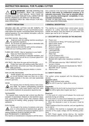
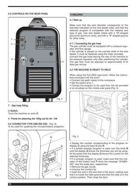
3.3 CONTROLS ON THE REAR PANEL<br />
T - Gas hose fitting.<br />
U-Switch.<br />
Turns the <strong>machine</strong> on and off.<br />
V- Points <strong>for</strong> attaching the 15Kg coil kit Art. 129<br />
3.4 CONNECTOR TYPE DB9 (RS 232) (Fig. 3)<br />
To be used <strong>for</strong> updating the microprocessor programs.<br />
12<br />
T<br />
V<br />
U<br />
0 1<br />
V<br />
®<br />
Via A.Costa, 24 - 40057-Cadriano-Bologna-Italy<br />
1~ f1<br />
f 2<br />
Nº<br />
MIG 2035/M<br />
PULSE<br />
15 A/14,7V-200 A/24V EN 60974-1<br />
EN 50199<br />
X(40°C) 35% 60% 100%<br />
U0<br />
I2 200A 160A 145A<br />
64V<br />
U2 24V 22V 21,2V<br />
S<br />
I1max = 32A<br />
U1 230V50/60 Hz<br />
I1eff = 20A<br />
MADE IN ITALY<br />
IP 23C<br />
W<br />
Art.<br />
285<br />
Fig. 2<br />
Fig. 3<br />
V<br />
4 WELDING<br />
4.1 Start-up<br />
Make sure that the <strong>wire</strong> diameter corresponds to the<br />
diameter indicated on the <strong>wire</strong> feeder roller, and that the<br />
selected program is <strong>com</strong>patible with the material and<br />
type of gas. Use <strong>wire</strong> feeder rollers with a "U"-shaped<br />
groove <strong>for</strong> aluminum <strong>wire</strong>s, and with a "V"-shaped groove<br />
<strong>for</strong> other <strong>wire</strong>s.<br />
4.1.1 Connecting the gas hose<br />
The gas cylinder must be equipped with a pressure regulator<br />
and flow gauge.<br />
If the cylinder is placed on the cylinder shelf of the <strong>wire</strong><br />
feeder, it must be fastened using the chain provided.<br />
Connect the gas hose leaving the rear of the <strong>machine</strong> to<br />
the pressure regulator, only after positioning the cylinder.<br />
The gas flow must be adjusted to approximately 8-10<br />
liters per minute.<br />
4.2 THE MACHINE IS READY TO WELD<br />
When using the Pull-2003 type torch, follow the <strong>instruction</strong>s<br />
enclosed with the torch.<br />
• Connect the earth clamp to the workpiece.<br />
• Set the switch U to 1.<br />
• Choose the program to be used from the list provided<br />
in an envelope on the mobile side panel (Fig. 4).<br />
Fig. 4<br />
• Display the number corresponding to the program on<br />
display Q using the keys O and R.<br />
• If a pulsed synergic program is used, turn the knob B<br />
until the display Q shows the thickness you will be using.<br />
At the same time the display G shows the current <strong>for</strong> the<br />
selected thickness.<br />
• If a synergic program is used, make sure that the indicator<br />
of the knobs I and P show the message "SYNER-<br />
GIC" and the scale zero, respectively.<br />
• Remove the gas nozzle.<br />
• Unscrew the contact tip.<br />
• Insert the <strong>wire</strong> in the <strong>wire</strong> liner of the torch, making sure<br />
that it is inside the roller groove and that the roller is in the<br />
correct position. Then close the door.