instruction manual for wire welding machine - Cebotechusa.com
instruction manual for wire welding machine - Cebotechusa.com
instruction manual for wire welding machine - Cebotechusa.com

Create successful ePaper yourself
Turn your PDF publications into a flip-book with our unique Google optimized e-Paper software.
2.3 PROTECTIONS<br />
2.3.1 Block protection<br />
In the event of a malfunction, a number with the following<br />
meaning may appear on the display G:<br />
52 = Start button pressed during start-up.<br />
53 = start button pressed during thermostat reset.<br />
56 = Extended short-circuit between the <strong>welding</strong><br />
electrode and the material to be welded.<br />
Shut the <strong>machine</strong> off and turn it back on.<br />
If different numbers appear on the display, contact technical<br />
service.<br />
2.3.2 Mechanical protection (safety button)<br />
When the movable side is opened, this activates the safety<br />
button which prevents operation of the <strong>welding</strong><br />
<strong>machine</strong>. This protection, indicated when the flashing<br />
message "OPn" appears on display G, avoids hazardous<br />
situations when the operator replaces the roller of the<br />
<strong>wire</strong> feeder unit or the <strong>welding</strong> electrode.<br />
2.3.3 Thermal protection<br />
This <strong>machine</strong> is protected by a thermostat, which prevents<br />
the <strong>machine</strong> from operating if the allowable temperatures are<br />
exceeded. In these conditions the fan continues to operate<br />
and the display G flashes the abbreviation "OPn".<br />
10<br />
®<br />
INVERTER<br />
MIG<br />
MIG MIG 2035/M 2035/M<br />
PULSE Art.285<br />
3 INSTALLATION<br />
Make sure that the supply voltage matches the voltage<br />
indicated on the specifications plate of the <strong>welding</strong><br />
<strong>machine</strong>.<br />
Mount a plug with an adequate capacity <strong>for</strong> the supply<br />
cable, making sure that the yellow/green conductor is<br />
connected to the earth pin.<br />
The capacity of the overload cutout switch or fuses<br />
installed in series with the power supply must be equivalent<br />
to the absorbed current I1 of the <strong>machine</strong>.<br />
3.1 START-UP<br />
The <strong>machine</strong> must be installed by skilled personnel. All<br />
connections must be carried out according to current<br />
regulations, and in full observance of safety laws (regulation<br />
CEI 26-10 - CENELEC HD 427)<br />
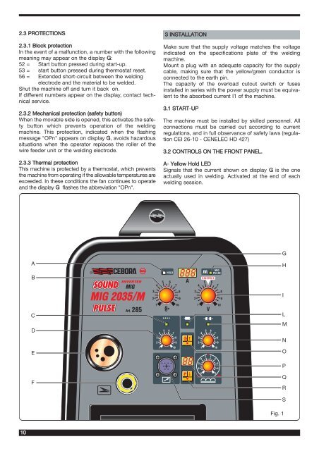
3.2 CONTROLS ON THE FRONT PANEL.<br />
A- Yellow Hold LED<br />
Signals that the current shown on display G is the one<br />
actually used in <strong>welding</strong>. Activated at the end of each<br />
<strong>welding</strong> session.<br />
A H<br />
B<br />
C<br />
D<br />
E<br />
F<br />
HOLD<br />
5 6<br />
4 7<br />
3<br />
8<br />
2<br />
9<br />
1<br />
10<br />
888<br />
A<br />
SINERGIC<br />
5 6<br />
4 7<br />
3<br />
8<br />
2<br />
9<br />
1<br />
10<br />
V<br />
5 6 5 6<br />
4 7 4 7<br />
MIG<br />
PULSE<br />
3 8 3<br />
8<br />
2 9 2<br />
9<br />
1 10 1 10<br />
88<br />
P<br />
1<br />
2<br />
3<br />
4<br />
5<br />
0 1<br />
2<br />
3<br />
4<br />
5<br />
G<br />
I<br />
L<br />
M<br />
N<br />
O<br />
P<br />
Q<br />
R<br />
S<br />
Fig. 1