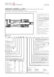
Hydraulic cylinders type CC • round heads
Hydraulic cylinders type CC • round heads
Hydraulic cylinders type CC • round heads

Create successful ePaper yourself
Turn your PDF publications into a flip-book with our unique Google optimized e-Paper software.
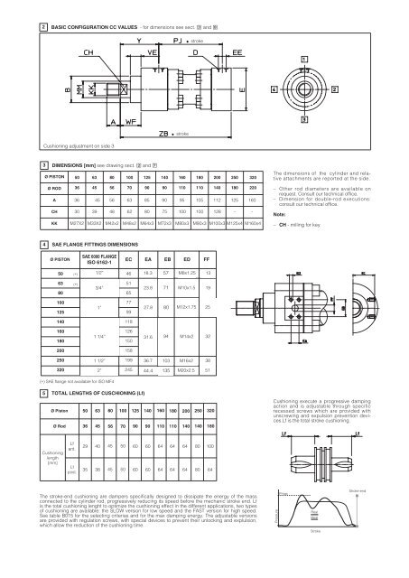
2 BASIC CONFIGURATION <strong>CC</strong> VALUES - for dimensions see sect. � and �<br />
Cushioning adjustment on side 3<br />
3 DIMENSIONS [mm] see drawing sect. � and �<br />
Ø PISTON 50<br />
Ø ROD<br />
A<br />
CH<br />
KK<br />
Ø Piston<br />
Ø Rod<br />
Cushioning<br />
length<br />
[mm]<br />
36<br />
36<br />
30<br />
M27X2<br />
Lf<br />
ant.<br />
Lf<br />
post.<br />
63<br />
45<br />
39<br />
80<br />
56<br />
100<br />
5 TOTAL LENGTHS OF CUSCHIONING (Lf)<br />
45<br />
M33X2<br />
56<br />
48<br />
M42x2<br />
70<br />
63<br />
62<br />
M48x2<br />
4 SAE FLANGE FITTINGS DIMENSIONS<br />
Ø PISTON<br />
50<br />
63<br />
80<br />
100<br />
125<br />
140<br />
160<br />
180<br />
200<br />
250<br />
320<br />
(∗)<br />
(∗)<br />
SAE 6000 FLANGE<br />
ISO 6162-1<br />
1/2”<br />
3/4”<br />
1”<br />
46<br />
51<br />
65<br />
77<br />
99<br />
118<br />
125<br />
90<br />
85<br />
80<br />
M64x3<br />
1 1/4”<br />
126<br />
150<br />
31.6<br />
1 1/2”<br />
2”<br />
(∗) SAE flange not available for ISO MF4<br />
158<br />
199<br />
245<br />
140<br />
29 40 45 50 60 60 64 64 64 80 100<br />
90<br />
stroke<br />
160<br />
110<br />
stroke<br />
180<br />
110<br />
50 63 80 100 125 140 160 180 200 250 320<br />
36 45 56 70 90 90 110 110 140 140 180<br />
35 38 45 50 60 60 64 64 64 80 64<br />
The stroke-end cushioning are dampers specifically designed to dissipate the energy of the mass<br />
connected to the cylinder rod, progressively reducing its speed before the mechanic stroke end. Lf<br />
is the total cushioning lenght to optimize the cushioning effect in the different applications, two <strong>type</strong>s<br />
of cushioning are available: the SLOW version for low speed and the FAST version for high speed.<br />
See table B015 for the selecting criterias and for the max damping energy. The adjustable versions<br />
are provided with regulation screws, with special devices to prevent their unlocking and explulsion,<br />
which allow the reduction of the cushioning time.<br />
90<br />
75<br />
M72x3<br />
95<br />
100<br />
M80x3<br />
105<br />
100<br />
EC EA EB ED FF<br />
18.3<br />
23.8<br />
27.8<br />
36.7<br />
44.4<br />
57<br />
71<br />
80<br />
94<br />
103<br />
135<br />
M8x1.25<br />
M10x1.5<br />
M12x1.75<br />
M14x2<br />
M16x2<br />
M20x2.5<br />
200<br />
140<br />
112<br />
128<br />
250<br />
180<br />
125<br />
320<br />
220<br />
M90x3 M100x3 M125x4 M160x4<br />
13<br />
19<br />
25<br />
32<br />
38<br />
51<br />
-<br />
160<br />
-<br />
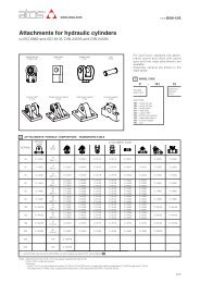
The dimensions of the cylinder and relative<br />
attachments are reported at the side.<br />
– Other rod diameters are available on<br />
request. Consult our technical office.<br />
– Dimension for double-rod executions:<br />
consult our technical office.<br />
Note:<br />
– CH - milling for key<br />
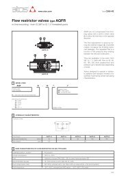
Cushioning execute a progressive damping<br />
action and is adjustable through specific<br />
recessed screws which are provided with<br />
unscrewing and expulsion prevention devices.Lf<br />
is the total stroke cushioning.<br />
Pressure<br />
Pmax<br />
Real<br />
Ideal<br />
Stroke<br />
Stroke-end