Hydraulic cylinders type CC • round heads
Hydraulic cylinders type CC • round heads
Hydraulic cylinders type CC • round heads

Create successful ePaper yourself
Turn your PDF publications into a flip-book with our unique Google optimized e-Paper software.
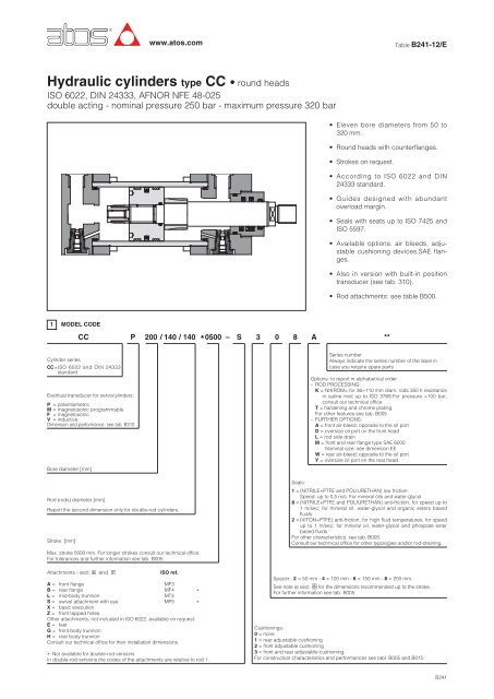
<strong>Hydraulic</strong> <strong>cylinders</strong> <strong>type</strong> <strong>CC</strong> <strong>•</strong> <strong>round</strong> <strong>heads</strong><br />
ISO 6022, DIN 24333, AFNOR NFE 48-025<br />
double acting - nominal pressure 250 bar - maximum pressure 320 bar<br />
1 MODEL CODE<br />
Cylinder series<br />
<strong>CC</strong><br />
<strong>CC</strong>=ISO 6022 and DIN 24333<br />
standard<br />
P<br />
Eventual transducer for servo<strong>cylinders</strong>:<br />
P = potentiometric<br />
M = magnetosonic programmable<br />
F = magnetosonic<br />
V = inductive<br />
Dimension and performance: see tab. B310<br />
Bore diameter [mm]<br />
Rod (rods) diameter [mm]<br />
Report the second dimension only for double-rod <strong>cylinders</strong>.<br />
Stroke [mm]<br />
www.atos.com<br />
200 / 140 / 140 0500 –<br />
Max. stroke 5000 mm. For longer strokes consult our technical office.<br />
For tolerances and further information see tab. B005.<br />
Attachments - sect. � and � ISO ref.<br />
A = front flange MF3<br />
B = rear flange MF4 *<br />
L = mid-body trunnion MT4<br />
S = swivel attachment with eye MP5 *<br />
X = basic execution<br />
Z = front tapped holes<br />
Other attachments, not included in ISO 6022, available on request:<br />
E = feet<br />
G = front body trunnion<br />
H = rear body trunnion<br />
Consult our technical office for their installation dimensions.<br />
* : Not available for double-rod versions.<br />
In double-rod versions the codes of the attachments are relative to rod 1.<br />
*<br />
S<br />
3<br />
0 8 A<br />
Table B241-12/E<br />
<strong>•</strong> Eleven bore diameters from 50 to<br />
320 mm.<br />
<strong>•</strong> Round <strong>heads</strong> with counterflanges.<br />
<strong>•</strong> Strokes on request.<br />
<strong>•</strong> According to ISO 6022 and DIN<br />
24333 standard.<br />
<strong>•</strong> Guides designed with abundant<br />
overload margin.<br />
<strong>•</strong> Seals with seats up to ISO 7425 and<br />
ISO 5597.<br />
<strong>•</strong> Available options: air bleeds, adjustable<br />
cushioning devices,SAE flanges.<br />
<strong>•</strong> Also in version with built-in position<br />
transducer (see tab. 310).<br />
<strong>•</strong> Rod attachments: see table B500.<br />
Series number<br />
Always indicate the series number of the label in<br />
case you require spare parts<br />
Options: to report in alphabetical order<br />
– ROD PROCESSING:<br />
K = NIKROM= for 36÷110 mm diam. rods 350 h resistance<br />
in saline mist up to ISO 3768.For pressure >100 bar,<br />
consult our technical office<br />
T = hardening and chrome plating<br />
For other features see tab. B005<br />
– FURTHER OPTIONS:<br />
A = front air-bleed; opposite to the oil port<br />
D = oversize oil port on the front head<br />
L = rod side drain<br />
M = front and rear flange <strong>type</strong> SAE 6000.<br />
Nominal size: see dimension EE<br />
W = rear air-bleed; opposite to the oil port<br />
Y = oversize oil port on the rear head<br />
Seals:<br />
1 = (NITRILE+PTFE and POLIURETHAN) low friction.<br />
Speed: up to 0,5 m/s. For mineral oils and water-glycol<br />
8 = (NITRILE+PTFE and POLIURETHAN) anti-friction, for speed up to<br />
1 m/sec; for mineral oil, water-glycol and organic esters based<br />
fluids.<br />
2 = (VITON+PTFE) anti-friction, for high fluid temperatures, for speed<br />
up to 1 m/sec; for mineral oil, water-glycol and phospate ester<br />
based fluids.<br />
For other characteristics, see tab. B005.<br />
Consult our technical office for other typologies and/or rod-draining.<br />
Spacer: 2 = 50 mm - 4 = 100 mm - 6 = 150 mm - 8 = 200 mm.<br />
See note at sect. � for the dimensions recommended up to the stroke.<br />
For further information see tab. B005<br />
Cushionings:<br />
0 = none<br />
1 = rear adjustable cushioning<br />
2 = front adjustable cushioning<br />
3 = front and rear adjustable cushioning<br />
For construction characteristics and performances see tabl. B005 and B015.<br />
**<br />
B241
2 BASIC CONFIGURATION <strong>CC</strong> VALUES - for dimensions see sect. � and �<br />
Cushioning adjustment on side 3<br />
3 DIMENSIONS [mm] see drawing sect. � and �<br />
Ø PISTON 50<br />
Ø ROD<br />
A<br />
CH<br />
KK<br />
Ø Piston<br />
Ø Rod<br />
Cushioning<br />
length<br />
[mm]<br />
36<br />
36<br />
30<br />
M27X2<br />
Lf<br />
ant.<br />
Lf<br />
post.<br />
63<br />
45<br />
39<br />
80<br />
56<br />
100<br />
5 TOTAL LENGTHS OF CUSCHIONING (Lf)<br />
45<br />
M33X2<br />
56<br />
48<br />
M42x2<br />
70<br />
63<br />
62<br />
M48x2<br />
4 SAE FLANGE FITTINGS DIMENSIONS<br />
Ø PISTON<br />
50<br />
63<br />
80<br />
100<br />
125<br />
140<br />
160<br />
180<br />
200<br />
250<br />
320<br />
(∗)<br />
(∗)<br />
SAE 6000 FLANGE<br />
ISO 6162-1<br />
1/2”<br />
3/4”<br />
1”<br />
46<br />
51<br />
65<br />
77<br />
99<br />
118<br />
125<br />
90<br />
85<br />
80<br />
M64x3<br />
1 1/4”<br />
126<br />
150<br />
31.6<br />
1 1/2”<br />
2”<br />
(∗) SAE flange not available for ISO MF4<br />
158<br />
199<br />
245<br />
140<br />
29 40 45 50 60 60 64 64 64 80 100<br />
90<br />
stroke<br />
160<br />
110<br />
stroke<br />
180<br />
110<br />
50 63 80 100 125 140 160 180 200 250 320<br />
36 45 56 70 90 90 110 110 140 140 180<br />
35 38 45 50 60 60 64 64 64 80 64<br />
The stroke-end cushioning are dampers specifically designed to dissipate the energy of the mass<br />
connected to the cylinder rod, progressively reducing its speed before the mechanic stroke end. Lf<br />
is the total cushioning lenght to optimize the cushioning effect in the different applications, two <strong>type</strong>s<br />
of cushioning are available: the SLOW version for low speed and the FAST version for high speed.<br />
See table B015 for the selecting criterias and for the max damping energy. The adjustable versions<br />
are provided with regulation screws, with special devices to prevent their unlocking and explulsion,<br />
which allow the reduction of the cushioning time.<br />
90<br />
75<br />
M72x3<br />
95<br />
100<br />
M80x3<br />
105<br />
100<br />
EC EA EB ED FF<br />
18.3<br />
23.8<br />
27.8<br />
36.7<br />
44.4<br />
57<br />
71<br />
80<br />
94<br />
103<br />
135<br />
M8x1.25<br />
M10x1.5<br />
M12x1.75<br />
M14x2<br />
M16x2<br />
M20x2.5<br />
200<br />
140<br />
112<br />
128<br />
250<br />
180<br />
125<br />
320<br />
220<br />
M90x3 M100x3 M125x4 M160x4<br />
13<br />
19<br />
25<br />
32<br />
38<br />
51<br />
-<br />
160<br />
-<br />
The dimensions of the cylinder and relative<br />
attachments are reported at the side.<br />
– Other rod diameters are available on<br />
request. Consult our technical office.<br />
– Dimension for double-rod executions:<br />
consult our technical office.<br />
Note:<br />
– CH - milling for key<br />
Cushioning execute a progressive damping<br />
action and is adjustable through specific<br />
recessed screws which are provided with<br />
unscrewing and expulsion prevention devices.Lf<br />
is the total stroke cushioning.<br />
Pressure<br />
Pmax<br />
Real<br />
Ideal<br />
Stroke<br />
Stroke-end
6 ATTACHMENTS<br />
Front tapped holes: Z<br />
Front flange attachment: A (ISO MF3)<br />
Rear flange attachment: B (ISO MF4)<br />
Mid-body trunnion: L (ISO MT4)<br />
Swivel attachment with eye: S (ISO MP6)<br />
B241
7 ATTACHMENTS - dimension in sect. �<br />
Front tapped holes: Z Diameters ø 140÷250<br />
Front flange attachment: A (ISO MF3)<br />
Rear flange attachment: B (ISO MF4)<br />
Mid-body trunnion: L (ISO MT4)<br />
Swivel attachment with eye: S (ISO MP6)<br />
stroke<br />
stroke<br />
stroke<br />
stroke<br />
stroke<br />
stroke<br />
stroke<br />
stroke<br />
stroke<br />
stroke
8 DIMENSIONS [mm] see drawing sect. � and �.<br />
Ø PISTON<br />
Ø ROD<br />
α, β<br />
AA<br />
B f9<br />
BG min<br />
CX H7<br />
D<br />
Emax<br />
EE<br />
EE1<br />
EP<br />
EX H12<br />
FB H13<br />
FC<br />
Lf (indicative)<br />
LTmin<br />
MSmax<br />
MT [Nm]<br />
NF<br />
RT<br />
TD f8<br />
TL<br />
TM h14<br />
UC max<br />
UM<br />
UVmax<br />
minimum stroke for<br />
version with attachments<br />
A,B,S,X (1)<br />
VD min<br />
VE<br />
WC<br />
WF<br />
minimum stroke<br />
for version with<br />
L attachment (1)<br />
XVmin<br />
XVmax<br />
Y<br />
(1) For strokes shorter than that one indicated on table, consult our technical office.<br />
Ø PISTON 50 63<br />
PJ<br />
ZB<br />
ZP<br />
XO<br />
50<br />
36<br />
63<br />
45<br />
32,5°, 25° 32°, 26°<br />
90<br />
63<br />
20<br />
32<br />
29<br />
108<br />
1/2”<br />
3/4”<br />
27<br />
32<br />
13,5<br />
132<br />
30<br />
40<br />
40<br />
30<br />
25<br />
n°8<br />
holes M10<br />
M8<br />
32<br />
25<br />
112<br />
160<br />
162<br />
108<br />
70<br />
4<br />
29<br />
22<br />
47<br />
175<br />
260<br />
105<br />
75<br />
23<br />
40<br />
36<br />
124<br />
3/4”<br />
1”<br />
35<br />
40<br />
13,5<br />
150<br />
40<br />
50<br />
50<br />
50<br />
32<br />
125<br />
180<br />
189<br />
124<br />
70<br />
4<br />
32<br />
25<br />
53<br />
185<br />
285<br />
80 100 125 140 160 180 200 250 320<br />
56 70 90 90 110 110 140 180 220<br />
35°, 20° 35°, 20° 35°, 20° 27,5°, 17,5° 25°, 20° 25°, 20° 25°, 20° 27°, 18° 25°, 28°<br />
128 152 188 215 241 275 295 365 458<br />
90 110 132 145 160 185 200 250 320<br />
23 30 33 33 43 40 40 58 70<br />
50 63 80 90 100 110 125 160 200<br />
36 42 42 52 52 52 52 58 69<br />
148 175 214 255 270 315 330 412 510<br />
3/4" 1" 1" 1 1/4” 1 1/4" 1 1/4” 1 1/4" 1 1/2" 1 1/2”<br />
1” 1 1/4” 1 1/4” 1 1/2” 1 1/2” 1 1/2” 1 1/2” 2” 2”<br />
40 52 66 65 84 88 102 130 162<br />
50 63 80 90 100 110 125 160 200<br />
17,5 22 22 26 26 33 33 39 45<br />
180 212 250 285 315 355 385 475 600<br />
45 55 60 60 65 65 65 90 100<br />
63 71 90 113 112 135 160 200 250<br />
63 71 90 113 112 118 160 200 250<br />
85 152 255 255 304 370 490 950 1750<br />
28 32 36 40 40 45 50 56 63 80<br />
n°8 n°8<br />
holes M18 holes<br />
M10 M12<br />
n°8<br />
holes<br />
M14<br />
n°8<br />
holes M22<br />
M16<br />
n°12<br />
holes M27<br />
M16<br />
n°12<br />
holes<br />
M18<br />
n°12<br />
holes -<br />
M20<br />
n°12<br />
holes<br />
M22<br />
n°12<br />
holes<br />
M27<br />
n°12<br />
holes<br />
M33<br />
40 50 63 80 90 100 110 125 160 200<br />
40 50 63 70 80 90 100 125 160<br />
150 180 224 265 280 320 335 425 530<br />
215 260 300 340 370 425 455 545 680<br />
230 280 350 405 440 500 535 675 850<br />
150 180 219 260 280 315 333 412 510<br />
20 25 50 50 50 70 70 80 120<br />
4 5 5 5 5 5 5 8 8<br />
36 41 45 45 50 55 61 71 88<br />
28 32 36 36 40 45 45 50 56<br />
60 68 76 76 85 95 101 113 136<br />
150 160 245 250 260 350 390 460 560<br />
290 320 410 440 465 540 590 690 820<br />
85+<br />
stroke<br />
120 134 153 181 185 205 220 260 310<br />
100+<br />
stroke 140+<br />
stroke 160+<br />
stroke 165+<br />
stroke 190+<br />
stroke 205+<br />
stroke 190+<br />
stroke 200+<br />
stroke 230+<br />
stroke 260+<br />
130<br />
stroke<br />
98 112<br />
80 100 125 140 160 180 200 250 320<br />
120 133 155 171 205 208 235 250 278 325 350<br />
244 274 305 340 396 430 467 505 550 652 764<br />
265 298 332 371 430 465 505 550 596 703 830<br />
305 348 395 442 520 580 617 690 756 903 1080<br />
The dimensions of the cylinder and relative<br />
attachments are reported at the side<br />
(sect. �).<br />
– Other rod diameters are available on<br />
request. Consult our technical office.<br />
– Dimension for double-rod executions:<br />
consult our technical office.<br />
Note:<br />
– EE - oil ports and drain are threaded<br />
according to GAS standards; with counterbore<br />
dimension D, according to DIN 3852-<br />
2 (big size series).<br />
When oversize oil port are provided, the<br />
dimension EE becomes EE1.<br />
– SAE FLANGES (opt. “M”) pre-arrangements<br />
for SAE flanges can be provided<br />
according to ISO 6162 with nominal<br />
dimension EE.<br />
– XV - For L-attachment. The XV value must<br />
be included between XV min. and XV<br />
max. and must always be reported in the<br />
model code. For execution with L-attachment,<br />
if the standard stroke is shorter than<br />
the min. value reported in the table, proper<br />
spacers are inserted and then it is<br />
necessary to take into account the complessive<br />
dimensions.<br />
– SPACERS: For strokes longer than 1000<br />
mm proper spacers (also for shorter<br />
strokes, on request) are designed to<br />
increase the rod and bore guide, protecting<br />
it from overloads and easy wear.<br />
Spacers can be omitted for cylinder<br />
working retracted.<br />
The table below shows the recommended<br />
dimensions depending on the stroke: for<br />
strokes longer than the ones shown in<br />
table, consult our technical office.<br />
strokes<br />
[mm]<br />
spacer<br />
code<br />
length<br />
[mm]<br />
1001<br />
÷<br />
1500<br />
1501<br />
÷<br />
2000<br />
2001<br />
÷<br />
2500<br />
2501<br />
÷<br />
3000<br />
2 4 6 8<br />
50 100 150 200<br />
– Inductive stroke sensors available on<br />
request. Consult our technical office.<br />
– MT: screw tightening torque (class 12.9).<br />
To obtain the real total dimensions add the<br />
values on the side to the stroke-end values<br />
and to the eventual spacers (see drawings<br />
of sect. � and �).<br />
N.B.: - for strokes, consider the following<br />
tolerances:<br />
<strong>•</strong> 0 + 1,2 mm for strokes up to 1000 mm<br />
<strong>•</strong> 0 + 2,5 mm for strokes longer than<br />
1000 mm<br />
B241
9 MASSES OF <strong>CC</strong> CYLINDER (in kg ± 5% tolerance)<br />
Ø Bore<br />
[mm]<br />
Ø Rod<br />
[mm]<br />
63 45<br />
80 56<br />
100 70<br />
125 90<br />
140 90<br />
180 110<br />
160 110<br />
200 140<br />
for 100 mm<br />
stroke<br />
20,1<br />
35,5<br />
58<br />
100<br />
144<br />
262<br />
189<br />
335<br />
each 100<br />
mm<br />
more<br />
2,6<br />
4,1<br />
6,5<br />
10,9<br />
14,2<br />
22,1<br />
17,1<br />
27,2<br />
attachment<br />
A, B<br />
4,2<br />
7,4<br />
11,4<br />
16,1<br />
22,5<br />
42,5<br />
29<br />
56<br />
10 <strong>CC</strong> TYPICAL SECTION WITH FRONT AND REAR CUSHIONING<br />
10/07<br />
BASIC MASSES<br />
for single rod x-execution<br />
For double executions and for Ø higher than 200, consult our technical office.<br />
Version with seals <strong>type</strong> G1<br />
11 MODEL CODE FOR SPARE KIT OF SEALS<br />
Spare kit of seals<br />
Type of seals<br />
Cylinder series<br />
attachment<br />
L<br />
4,8<br />
7,5<br />
12,6<br />
22<br />
31,1<br />
52,2<br />
40,3<br />
64<br />
Piston diameter [mm]<br />
ADDITIVE MASSES<br />
depending on attachment and options<br />
attachment<br />
S<br />
4,1<br />
6,3<br />
10,3<br />
19,6<br />
28,7<br />
59,8<br />
37,8<br />
82<br />
front<br />
cushioning<br />
0,3<br />
0,5<br />
0,8<br />
1,2<br />
1,2<br />
2,5<br />
1,7<br />
2,5<br />
rear<br />
cushioning<br />
POS. DESCRIPTION MATERIAL POS. DESCRIPTION MATERIAL POS. DESCRIPTION<br />
MATERIAL<br />
1 Rod Chrome-plated steel 10 “O” ring seal Nitrile rubber 21 s Steel and nitrile rubber<br />
2 Wiper Nitrile rubber PTFE 11 Piston Steel<br />
22 Counter flange Steel<br />
2.1 Wiper Poliurethan 12 Piston seal Nitrile rubber and PTFE 23 Cylinder housing Steel<br />
3 Rod seal Nitrile rubber PTFE 13 Low-friction guide ring PTFE<br />
24 “O” ring seal Nitrile rubber<br />
3.1 Rod seal Poliurethan 14 Screw stop pin steel<br />
25 Rear cushioning piston Hardened steel<br />
4 Rod guide ring Cast iron or bronze 15 “O” ring seal Nitrile rubber 26 Piston locking nut Steel<br />
5 Anti-extrusion PTFE<br />
16 Anti-extrusion PTFE<br />
27 Screw stop pin Steel<br />
6 “O” ring seal Nitrile rubber 17 Forward cylinder head Steel<br />
28 Counter flange Steel<br />
7 Anti-extrusion PTFE<br />
18 “O” ring seal and Anti-extrusion Nitrile rubber and PTFE 29 Rear cylinder head Steel<br />
8 “O” ring seal Nitrile rubber 19 Stop ring Steel<br />
30 screw TCEI Steel class 12.9<br />
9 Forward cushioning piston Hardened steel 20 Metering rod Steel<br />
SP – G 8 – <strong>CC</strong> – 200 / 140/140 **<br />
1<br />
1<br />
1,5<br />
2<br />
2<br />
5<br />
3<br />
5<br />
25 mm<br />
spacer<br />
1<br />
1,65<br />
2,3<br />
4,3<br />
5,3<br />
8,7<br />
6,3<br />
11<br />
Series number<br />
Always indicate the series number of the<br />
label<br />
Rod (rods) diameter [mm]<br />
Indicate the second dimension for double rod <strong>cylinders</strong> only