CR51-Version 179 - IEEE
CR51-Version 179 - IEEE
CR51-Version 179 - IEEE
- No tags were found...

Create successful ePaper yourself
Turn your PDF publications into a flip-book with our unique Google optimized e-Paper software.
Climate ChangeDon’t Ignore – Deal With it!Climate Change Technology Conference 2006Engineering Opportunities and Challengesin the 21st CenturyMay 9-12, 2006Ottawa Congress CentreThe Engineering Institute of Canada and it Societies offertheir inaugural Climate Change Conference. Come anddiscover the latest technology that looks at the opportunitiesand the challenges.Featured SpeakersAllan Amey, CEO, Climate Change CentralPierre Coulombe, President, NRCTravis Engen, President and CEO, AlcanJohn Grace, Director, Fluidization Research CentreMartin Hoffert, Professor, New YorkUniversityDonald Lemmen, NRCanMarc Rosen, Dean of Engineering, UOITVolker Thomsen, President, St.Lawrence CollegeMalcolm Wilson, Director, International Test Centrefor CO 2 CaptureVisit www.ccc2006.ca
<strong>IEEE</strong> CanadaOfficersDirector/President - W.O. (Bill) KennedyDirector/President Elect - Robert HannaPast Director/President - Mohd. El-HawarySecretary - Elmer BourqueTreasurer - Rob AndersonGroup ChairsExternal Relations: Scott LowellMember Services Group Chair: Hilmi TuranliPublications & Communications: Om MalikArea ChairsCanada Central: Bruno DiStefanoCanada East: Gerard DunphyCanada West: Dave KempOperating Committee ChairsAwards & Recognition - Vijay BhargavaCONAC - Witold KinsnerEducational Activities - Scott LowellGOLD Programme - Verona WongLife Member Chapter Coordinat.- Ron PottsMembership Development: Hilmi TuranliRegional Student Rep. - Lori HoganSections/Chapters Suppt. - Ferial El-HawaryStandards - Jim GurneyStrategic Planning - Robert HannaStudent Activities - Janet BradleyTranslation Chair - Marc ProvencherWomen in Engineering - Anna ZyzniewskiDirector Emeritus - Ray FindlayDirector Emeritus - Wally ReadPublicationsCanadian Review - (see on this page)CJECE -Witold Kinsner & Xavier MaldaqueElectr. Newsletter Editor - Jeffery MackinnonWebmaster - Robert AldenSection ChairsCanadian Atlantic - Scott MelvinHamilton - Blair MacCuishKingston - Hisham El-MasryKitchener/Waterloo -Anthony KormosLondon - Ashfaq Kash HusainMontréal - Amir AghdamNew Brunswick - Brent PetersenNewfoundland & Labrador - Mike JanesOttawa - Maike MillerPeterborough - Sean DunneQuebec - Andre MorinNorth Saskatchewan - Andrew KostiukNorthern Canada - Keith BrownSaint Maurice - Dominic RivardSouth Saskatchewan - Raman ParajapeSouthern Alberta - Lawrence WhitbyToronto - Kostas PlataniotisVancouver - Dejan LenasiVictoria - David GregsonWinnipeg - Ani Gole<strong>IEEE</strong> Canada AdministratorCathie LowellThe <strong>IEEE</strong> Canadian Review is published 3 times/year as follows:Winter (to appear in April); Spring/Summer (to appear in August);Fall (to appear in December). Its principal objective is to project animage of the Canadian electrical, electronics, communications andcomputer engineering professions and their associated academic andbusiness communities to:(i)(ii)<strong>IEEE</strong> Canadian ReviewGeneral InformationCanadian members of <strong>IEEE</strong>;Canadian members of the profession and community who arenon-members of <strong>IEEE</strong>;(iii) The associated Canadian academic (i.e. universities, colleges,secondary schools), government and business communities.To ensure that the <strong>IEEE</strong> Canadian Review has the desired breadthand depth, editors are responsible for screening articles submittedaccording to the following general themes:1- National Affairs 4- Education 7- Computers2- International Affairs 5- Power 8 - Electronics3- Industry 6- CommunicationsAdvertising PolicyOrganizations are invited to place corporate advertising in the <strong>IEEE</strong>Canadian Review. For information regarding rates and copyrequirements, please contact the Managing Editor.CirculationThe circulation of the <strong>IEEE</strong> Canadian Review is the entiremembership of <strong>IEEE</strong> Canada, representing over 12,000 subscribers.Information for AuthorsAuthors are invited to contribute submissions in electronic form tothe <strong>IEEE</strong> Canadian Review. Please contact one of the editors.Responsibility for the content rests upon the authors and not the<strong>IEEE</strong>, or its members.Annual Subscription PriceFree of charge to all <strong>IEEE</strong> members in Canada. For <strong>IEEE</strong> membersoutside Canada: $20.00/year. Non-members: $35.00/year. Corporationsand libraries: $37.50/year. Additional copies may be ordered ata cost of $7.50 each from the Managing Editor.Reprint PermissionAbstracting is permitted with credit to the source. Libraries are permittedto photocopy for private use of patrons. Instructors are permittedto photocopy isolated articles for non-commercial classroomuse without fee. For other copying, reprint or republication, pleasewrite to the Managing Editor. The <strong>IEEE</strong> Canadian Review is printedin Canada, postage paid at Toronto, (Ontario).Change of address• Do-it-yourself with My<strong>IEEE</strong>: http://www.ieee.org/myieee• Email: address.change@ieee.org• Tel: 1 (800) 678-4333• Mail: <strong>IEEE</strong> Service Center445 Hoes Lane, P.O. Box 1331Piscataway, NJ 08855-1331, USAMember of / membre constituant deEngineering Institute of Canadal'Institut canadien des ingénieursManaging Co-EditorsCo-Rédacteurs en chefEric HoldrinetConsulat général du Canada à L.A.550 S. Hope Str., 9th FloorLos-Angeles, CA 90405, USAtel: (213) 346-2758fax: (213) 346-2767e.holdrinet@ieee.orgTerrance J. MalkinsonEngagement Services OrganizationGE Capital ITS Inc.Calgary, AB T2P 3P2tel: 403-282-1065t.malkinson@ieee.orgAdvertising ManagerDirecteur de la publicitéVijay K. SoodHydro-Québec (IREQ)1800 boulevard Lionel-BouletVarennes, Québec. J3X 1S1tel: (450) 652-8089fax: (450) 652-8181v.sood@ieee.orgAssociate EditorsAdjoints à la rédactionSamuel PierreDept. of Computer EngineeringEcole Polytechnique of MontrealP.O. Box 6079Station Centre-VilleMontreal, QC H3C 3A7tel: (514) 340-4711 Ext. 4685samuel.pierre@polymtl.caCamille-Alain RabbathDefence Research & Dev. Canada2459 Pie-XI Blvd. NorthVal-Belair, QC G3J 1X5tel: 418-844-4000 x4756camr@ieee.orgAlain Zarka4375 rue BeaubienQuébec (QC) G2A 3Z2tel: 418-847-5324azarka@ieee.orgHabib HamamFaculté d'ingénierieUniversité de Moncton165, avenue MasseyMoncton, NB E1A 3E9tel: 506-858 4762habib.hamam@ieee.orgThe National Library of CanadaISSN 1481-2002La Bibliothèque nationale du Canada<strong>IEEE</strong> Canadian Review - La Revue canadienne de l’<strong>IEEE</strong> is published by The Institute of Electrical and Electronics Engineers, Inc.’s Canadian unit. All rights reserved. © 2005 by The Instituteof Electrical and Electronics Engineers, Inc., 3 Park Avenue, New York, NY 10016-5997, U.S.A. The editorial content of this magazine does not represent official positions of the <strong>IEEE</strong> orits organisational units. Return Canadian undeliverable addresses to: <strong>IEEE</strong> Canada, C/O Cathie Lowell, Administrator, 18 Robinhood Drive, Dundas, Ontario, L9H 4G1.2<strong>IEEE</strong> Canadian Review — Fall / Automne 2005
Canadian Newslog / Coupures de presse CanadienneNewslog EditorCoupures de presseRédacteur desAlexandre Abecassis is a patentagent trainee in Montreal atOgilvy Renault, Lawyers andPatent and Trade-mark Agents.Alexandre Abecassis travaille àMontréal chez Ogilvy Renault,Avocats et agents de brevets etde marques de commerce,comme agent de brevets enformation.Send any news clippings you wouldlike to contribute via e-mail toalexandre.abecassis@ieee.orgVeuillez faire parvenir les coupuresde presse proposées par e-mail àalexandre.abecassis@ieee.orgOTTAWA, ON, May 31, 2005.XINK Laboratories has announcedthe first on-press manufacture offunctional UHF RFID transponderlabel. The antenna of the RFIDtransponder label was printed usingXINK silver UHF antenna ink andthe resulting four-color adhesiveRFID label real over 14 feet.VANCOUVER, BC, Oct. 13, 2005.Nicer Canada has announced thecompletion of the BC’s CivicElection Campaign Call center. Inthe project, a large VoIP gatewaywas installed to provide more than96 phone lines to handle large callcentre operations. The VoIP gatewayenables the providing of featuressuch as fax through email, remoteextension, inter-office calls for multiplelocations, telephone conference,interactive voice response system,etc.MONTREAL, QC, Oct. 31, 2005.Ubisoft Canada, a large video gameproducer, has launched its UbisoftCampus which is a training centeroffering programs developed tocover competencies required in theproduction of video games. A scholarshipprogram has also been developedin order to encourage studentsto pursue a career in the video gameindustry.OTTAWA, ON, Oct. 27, 2005. 3,000bar code scanners have been suppliedby Metrologic Instruments toPG Elections who will be usingthem in the Canadian electoralprocess. Each voter, equipped with abar coded voter identification cardwill go to the polls, have their cardscanned using the scanner and thenmake their choice of leaders.OTTAWA, ON, Oct. 24, 2005.Dinmar has announced that theOttawa Hospital in Ontario has completedthe first stage of a broad-scaleAdvertising in in the the <strong>IEEE</strong> Canadian Review<strong>IEEE</strong> Canada lets you advertise to a highly knowledgeable workforcewith high disposable incomes. The <strong>IEEE</strong> Canada platformwas designed specifically to meet your needs and includes:✓ Innovative tools and services selling your products to ourmembers.✓ Quick and easy program integration.You can expect more from the <strong>IEEE</strong> Canada team.We provide:✓ Technical Integration - Responsible for technical support andintegration assistance.✓ Account Development - Provides support in the areas of programpromotion, performance and growth.Did You Know that the <strong>IEEE</strong> Canadian Review✓✓✓✓Is a National journal reaching some 16,000 Electrical andComputer engineers.Reaches some of the most highly paid technical talent in Canada.Is published three times per year.Is available Online at www.ieee.ca.To learn more about advertising opportunities, contact:V. Sood, Advertising Managerv.sood@ieee.orgPhone: 450-652-8089implementation of the company’sJava(TM)-based electronic healthrecord platform. The platformenables over 6000 clinicians toaccess instantly patient lists andintuitive summaries along withdetailed results and configurableviews. Care providers also benefitfrom a wide variety of automatedclinical decision support assistants,which streamline workflow andimprove care quality.MISSISSAUGA, ON, Oct. 3, 2005.Certicom has announced thatnCipher has licensed Certicom’sIntellectual Property portfolio tomeet customer demand for ellipticcurve cryptography (ECC) and alsoto meet requirements from theNational Security Agency (NSA) forsecuring classified and unclassifiedgovernment communications. Theagreement allows nCipher to useECC and other related Certicompatents as the public-key securitytechnology in its hardware securitymodules and software solutions.MONTREAL, QC, Sep. 21, 2005.The Université of Montréal andUbisoft have signed an agreementfor the joint development ofresearch and training projects in thefield of game design. Their primarycollaboration will be on designing agraduate program to be offered onthe Ubisoft campus, which willinclude a range of research activitiesdirectly linked to game design.OTTAWA, ON, Sep. 8, 2005. ProtusIP solutions has launched an interactivevoice messaging solution thatincludes a new survey and pollingfeature designed for companies whorequire immediate feedback withinbusiness operations. Organizationcan now send telephone surveys tokey contacts and expect an immediateresponse, along with detailed,real-time reports.MONTREAL, QC, Aug. 30, 2005.Electronic Arts has announced a$2.6M training program that willprovide its growing workforce ofgame makers in Montreal with thetechnical and creative skills theyneed to stay on the cutting-edge asthey develop the next-generation ofinteractive entertainment. The curriculumwill feature courses in:performance technology, graphics,engineering as well as project andpeople management.MARKHAM, ON, Sep. 21, 2005. Anew RFID center will be built andwill act as a focal point for Canadianindustry RFID discussions. It willprovide not only educational capabilitybut also a product testing facility.The center will focus on theretail, produce and consumer packagedgood industries and demonstrateshow RFID can enable a moreaccurate and cost effective way ofimplementing food traceability offrozen, fresh and dry food.MONTREAL, QC, Aug. 31, 2005.CAE has signed a 10-year agreementwith UK-based Virgin AtlanticAirways to provide training forpilots of the carrier’s entire fleet ofAirbus A340-600 and Boeing 747-400 aircraft. The total contract valuemay vary between $60M and $92Mover 10 years depending on options.MONTREAL, QC, May 30, 2005.Nstein Technologies has won the“Excellence OCTAS”, the highesthonour awarded by the Federationde l’Informatique du Quebec (FIQ),at the OCTAS 2005 Gala, as well asthe “Technology InnovationOCTAS” for the early warning andmonitoring solution derived from itsGlobal Intelligent InformationManagement technology platform.TORONTO, ON, May 18, 2005.University de Sherbrooke has selectedDELL servers to power two newhigh-performance computing clusters(HPCC) used for scientificresearch in areas such as astrophysics,computational chemistry,bi-engineering, fluid dynamics, datamining, temperature superconductivity,nanoelectronics, pharmaceuticaldevelopment and weather andclimate forecasting. The supercomputerwill have a theoretical performanceof 8.3 trillion operations persecond (TeraFLOPS).MONTREAL, QC, Oct. 25, 2005.Bell Canada has announced that itsIP telephony service is available forcustomers in the Greater MontrealArea. The service is already offeredin Toronto. It will be possible tokeep an existing phone number withthe new service.CALGARY, AB, Oct. 5, 2005. Telushas announced the launch of a wirelessfield ticketing solution designedfor the oil and gas industry thatallows companies to electronicallycapture crucial operational statusand billing information from thefield.OTTAWA, ON, Aug. 26, 2005.Canarie, Canada’s research and educationnetwork organization andRogers Telecom announced a multimilliondollar contract wherebyRogers will provide a wide range ofnetwork services to support theCA(*) net 4 network. The CA(*) net4 network is Canada’s nationalresearch and innovation network.<strong>IEEE</strong> Canadian Review — Fall / Automne 2005 3
Director’s ReportWhen the members of Region 7 lent me the Presidency of <strong>IEEE</strong>Canada I laid out a course of action on what I would do overthe next two years. The time has quickly passed and in mylast article for the Canadian Review I find myself lookingback at what I was able to accomplish. Also, <strong>IEEE</strong> Canada isfaced with some new challenges and I want to briefly discuss those.Probably the most important thing that was accomplished was the newgovernance structure. This is now in place and with the Tampa meetingthe Operations Manual for Region 7 has been presented and approved.<strong>IEEE</strong> Canada’s revised Bylaws were approved at the June RAB meeting.The new structure allows the ExCom to oversee all activities in Region7 and when you open a door, you expose some opportunities. More onthis later.On the finance side, we put in place two important committees, Auditand Investment. The Audit Committee met in Saskatoon during theSpring Meeting and delivered its report to the <strong>IEEE</strong> Canada Board. Theirrecommendations have been accepted and are now incorporated into ouroperating procedures. An Investment Committee that reported in Tampais examining how we protect our assets and how we access our surplusfunds for the good of <strong>IEEE</strong> Canada.I wanted to develop a Power System Seminar that I would be able tooffer to Sections when I visited. That has been done and over the lasttwo years it has been presented to six Sections in Canada, Association ofProfessional Engineers Geologist and Geophysicists of Alberta andRegion 5. I have visited 12 Sections and helped celebrate significantanniversaries in some. By year’s end I will have participatedin two <strong>IEEE</strong> Milestone events, the Nelson RiverHVDC in Winnipeg and the 735 kV transmission in Quebec.The addition of a third meeting concurrent with the studentshas allowed the ExCom to interface with the students.Members of the ExCom were called on to make presentationsto the SAC meeting. When I visited Sections I tried to findtime to address the student branches. Two of the PowerSystem Seminars were coordinated by the student branches.Telus has very generously established a prize for a studentcompetition. The first contest was held this year with thefinals held in Vancouver preceding the student and ExCommeetings. Lakehead University team captured first prize and on Saturdaynight they demonstrated their award winning project at the conclusion ofthe joint dinner for the students and ExCom. The agreement betweenTelus and <strong>IEEE</strong> Canada will run for five years, and we can expect morecompetition over the next four years.Thanks to hard work by the Quebec Section, Sections Congress 2008will be held in Quebec City in 2008. In August I visited Quebec Cityalong with staff from Piscataway for a site visit of the facilities forSections Congress. The local chair, Paul Fortier, is assembling his teamand I’m sure <strong>IEEE</strong> Canada will once again show the <strong>IEEE</strong> world a goodparty.I want to conclude by bringing two issues to the attention of <strong>IEEE</strong>Canada members. They are also opportunities for us to enhance andstrengthen <strong>IEEE</strong> Canada.The first is engaging Sections. The <strong>IEEE</strong> Canada Board and especiallyits ExCom exists to assist the Sections in exposing <strong>IEEE</strong> to others. Partof <strong>IEEE</strong>’s mission statement is “enabling members’ careers”. TheExCom depends on the Sections for the delivery of <strong>IEEE</strong> products andservices and in this regard I’m talking about technical matters. While theExCom and the <strong>IEEE</strong> Canada Board can develop and facilitate these programswe depend on the local Sections to deliver the goods! In our fastchanging world, we must be doing this.The second issue is finances. Past <strong>IEEE</strong> Canada Treasurers were foresightedenough to hedge our funds against the declining Canadian dollar.This had a good and a bad side. The bad side was it cost our membersmore each year as the Canadian dollar declined against its Americancounterpart. The “good” was that <strong>IEEE</strong> Canada finances experienced“windfall” gains from the declining dollar. Now the converse is true.With the Canadian dollar at record highs, the cost of membership isgoing down. However, the “windfall” gains are gone. For every 1 centincrease in the Canadian dollar, <strong>IEEE</strong> finances are affected by approximately$3,000.These are not problems; rather they are opportunities for us to enhancethe stature of <strong>IEEE</strong> and <strong>IEEE</strong> Canada.Finally, I want to thank all those <strong>IEEE</strong> members who made my visits totheir Sections more memorable, and also to the student members whomade the local arrangements for the Power System Seminar.Rapport du PrésidentLorsque les membres de la Région 7 m’ont élu président del’<strong>IEEE</strong> Canada, j’ai dressé un agenda des réalisations que j’espéraisaccomplir durant les deux ans de ce mandat. Deux ansplus tard, dans ce dernier article, je veux passer en revue ce quia été accompli. Également, je veux mentionner certain desnouveaux défis auquel fait face l’<strong>IEEE</strong>.La principale réalisation a été la mise en place de la nouvelle structure degouvernance. Le manuel d’opération de la Région 7 a été approuvé cetautomne. La révision des Règlements de l’<strong>IEEE</strong> Canada a été approuvéeen juin. La nouvelle structure de gouvernance permet au Comité Exécutifde superviser toutes les activités de la Région 7. Ceci ouvre de nouvellespossibilités dont nous parlerons plus loin.Coté finances nous avons créé deux comités importants: Vérification etInvestissement. Le premier s’est réuni au printemps et a présenté sonrapport au comité de direction. Ses recommandations ont été approuvéeset font désormais partie de notre manuel d’opération. Le Comitéd’Investissement qui a présenté son rapport à Tampa examine commentprotéger nos actifs et, encore plus important, comment utiliser nos surpluspour le plus grand bénéfice de l’<strong>IEEE</strong> Canada.Un séminaire sur les Systèmes électriques a été créé et présenté à sixSection au Canada, à l’Association Professionnelle des Ingénieurs,Géologues et Géophysiciens de l’Alberta, et à la Région 5. J’ai visitédouze Sections et célébré avec certaines d’entre elles des anniversairesimportants. D’ici la fin de l’année, je vais avoir participé à l’inaugurationde deux réalisations d’envergures pour l’<strong>IEEE</strong> : le HVCC dela rivière Nelson à Winnipeg et la ligne de transmission de735Kv au Québec.L’addition d’une troisième réunion concurrente à celle desétudiants a permis au Comité Exécutif d’interagir avec eux.Lors de mes visites de Sections, j’ai tâché de trouver dutemps pour rencontrer les membres étudiants. Deux des séminairessur les Systèmes électriques ont été présentés à lademande de branches étudiantes.Telus a généreusement établi un prix pour une compétitionétudiante. Le premier concours a eu lieu cette année, avec lesfinales à Vancouver avant les réunions des étudiants et duComité Exécutif. L’équipe de l’U.Lakehead a remporté lepremier prix et présenté son projet lors du souper conjoint Etudiants -Comité Exécutif. L’entente entre Telus et <strong>IEEE</strong> Canada s’étend sur cinqans; nous pouvons nous attendre à de nouvelles compétitions au coursdes quatre prochaines années.Grâce au travail acharné de la Section de Québec, le congrès des Sectionss’y tiendra en 2008. En août, avec des employés de Piscataway,nous avons visité les installations. Le président de la Section, PaulFortier, recrute son équipe et je suis sûr qu’avec eux l’<strong>IEEE</strong> Canadamontrera à la communauté de l’<strong>IEEE</strong> comment elle sait recevoir.Avant de terminer, je dois attirer votre attention sur deux sujets d’importancepour les membres de l’<strong>IEEE</strong> Canada:L’implication des Sections: Le Comité de direction de <strong>IEEE</strong> Canada etson Comité Exécutif sont là pour aider les Sections à introduire l’<strong>IEEE</strong> àune nouvelle audience. Une des missions de l’<strong>IEEE</strong> est d’aider les membresdans leurs carrières. Le Comité Exécutif dépend des Sections pourla dissémination des produits et services de l’<strong>IEEE</strong>, spécialement l’informationtechnique. Le Comité Exécutif et le Comité de direction peuventfaciliter la livraison de ces programmes, mais il revient aux Sectionsde les présenter aux membres. Dans ce monde en changement, nousdevons remplir notre mission.Nos finances: Les Trésoriers précédents ont prévenu un impact tropimportant du déclin du dollar canadien par l’utilisation d’instrumentsfinanciers. Ceci a eu un bon et un mauvais coté: il en a coûté plus à nosmembres chaque année lors du déclin de la devise canadienne vis-à-visde la devise américaine; par contre l’<strong>IEEE</strong> Canada a accumulé de petitsgains de taux de changes. Maintenant la situation est inversée. Avec undollar canadien élevé, le coût pour les membres diminue, mais les gainsaccumulés ont disparu. Pour chaque augmentation de 1 cent du dollarcanadien, les finances de l’<strong>IEEE</strong> Canada sont affectées par environ$3,000.Ces sujets ne sont pas que des problèmes: ce sont des occasionsd’améliorer la stature de l’<strong>IEEE</strong> et de <strong>IEEE</strong> Canada.J’aimerai, en terminant, remercier tous les membres de <strong>IEEE</strong> qui ontrendu mémorables mes visites des différentes sections, et les membresétudiants qui se sont occupés des arrangement locaux lors des présentationsdu séminaire sur les Systèmes électriques.W.O. (Bill) Kennedy, P.Eng., FEIC, SM<strong>IEEE</strong> · 2004 - 2005 <strong>IEEE</strong> Canada President4<strong>IEEE</strong> Canadian Review — Fall / Automne 2005
History / Histoire<strong>IEEE</strong> Honours Historical Achievement in Electrical EngineeringFollowing on the three previous Canadian dedications atDeCew Falls in Ontario (2004) and Signal Hill and Heart’sContent in Newfoundland (both in 1985), The Institute ofElectrical and Electronics Engineers (<strong>IEEE</strong>) History Centerrecently recognized The Nelson River High Voltage DirectCurrent (HVDC) Transmission System as a pioneering engineeringproject in the long distance transmission of electrical power and energy.The Manitoba Electrical Museum, located in Winnipeg, Manitoba, wasthe site of the Milestone Dedication Ceremony on June 3rd 2005. Membersof the <strong>IEEE</strong> Winnipeg Section together with Manitoba Hydro staffand retirees as well as other organizations that played a part in the projectwere in attendance. Mr. Bill Kennedy, President of <strong>IEEE</strong> Canada,unveiled a commemorative plaque that reads:byLindsay Ingram, LS<strong>IEEE</strong>and Public Affairs Manitoba Hydro<strong>IEEE</strong> MILESTONE IN ELECTRICAL ENGINEERINGAND COMPUTINGHIGH VOLTAGE DIRECT CURRENT, 1972On 17 June 1972, the Nelson River High Voltage Direct Current(HVDC) transmission system began delivery of electricpower. It used the highest operating voltage to deliver thelargest amount of power from a remote site to a city. Thebipolar scheme gave superior line reliability and the innovativeuse of the controls added significantly to the overall systemcapabilities. Finally, the scheme used the largest mercuryarc valves ever developed for such an application.JUNE 2005INSTITUTE OF ELECTRICAL & ELECTRONICS ENGINEERSIn the 1960s, the key to developing Northern Manitoba’s rich hydroelectricresources was finally discovered in the form of long distance highvoltage direct current (HVDC) technology. Lower line losses than conventionalAC transmission gave HVDC the edge and the system hasgone on to prove itself a highly reliable system that is now the backboneof the supply of power and energy, delivering over 75% of theprovince’s electricity output to Manitobans and export customers. ManitobaHydro has gone on to become world renowned for its expertise andresearch and development in this field.Manitoba Hydro’s HVDC system consists of two transmission lines carriedby two rows of identical steel towers running 895 kilometers fromGillam in northern Manitoba south to the Dorsey converter station closeto Winnipeg. One line has its northern terminus at the Radisson converterstation close to Gillam and the other extends another 42 kilometersto the Henday converter station. Manitoba Hydro’s three largesthydroelectric generating stations are located on the Nelson River atKettle, Long Spruce, and Limestone, representing a total capacity of3570 Mw for transmission.The Government of Canada assisted with a financing agreement tomake the project possible. Atomic Energy Canada Ltd. on behalf of thegovernment was responsible for the construction of the project and theprimary consultant was Teshmont Consultants LP.For Manitoba Hydro: Len Bateman, Bob BrennanFor <strong>IEEE</strong>: Bill Kennedy, Lindsay Ingram, Dr. Ani GoleNelson River HVDC Mercury Arc ValvesConstruction of the transmission lines began in January 1968 and thefirst transmission of power took place in June 1972. The two transmissionlines, known as Bipole 1 and Bipole 2, consisting of some 4000guyed steel towers, took about three years to build. Having to traverselarge tracts of muskeg country meant that much of the work had to bedone during the winter when the ground was frozen.The three converter stations, comprised of switchyards and converterbuildings containing the valves, are extremely large facilities and are theheart of the conversion process. The original Bipole 1 mercury arcvalves have now been replaced with solid state thyristor valves.HVDC transmission of electricity, particularly over such a long distancewas relatively new in the late 1960s and ’70s. Manitoba Hydro and localengineering consultants specializing in the new technology gained aninternational reputation for expertise in this technology and visitors fromaround the world have come to Manitoba to witness the Nelson Riversystem in action. Manitoba consultants and manufacturers have workedon HVDC systems in many parts of the world.With its high reliability, flexibility of operation, and inherent stability,the Nelson River HVDC Transmission System has proven its worth.The <strong>IEEE</strong> Winnipeg Life Members Chapter submitted this Milestoneproposal and nomination with the support of Manitoba Hydro staff andretired personnel.About the AuthorLindsay Ingram is a retired Director of theSystem Planning Division with Manitoba Hydrowhere he spent 33 years. In retirement, hebecame Interim Director of the Manitoba HVDCResearch Centre located in Winnipeg, followedby consulting assignments. He is currently avolunteer board member of the ManitobaElectrical Museum and is also a Life Member ofthe <strong>IEEE</strong>, the Association of ProfessionalEngineers and Geoscientists of the Province ofManitoba, and the Canadian Society for SeniorEngineers (CSSE/EIC).<strong>IEEE</strong> Canadian Review — Fall / Automne 2005 5
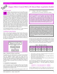
Telecommunications / TélécommunicationsTechnological Advances in DSL1.0 IntroductionThe deregulation of the telecommunication in the 90s broughtabout a competitive environment for broadband technology.Although DSL, Digital Subscriber Line, has been late to enterthe market compared to cable networks, it has made progress incapturing market share - capitalizing on cost as well as bundling with otherservices. Figure 1 represents the Top 20 countries in terms of DSL users.by Naresh Kurada MSEE<strong>IEEE</strong> Toronto SectionAbstractThe deregulation of Telecommunication in the 1990s has unleashedthe Broadband Access technology epitomized by the service providedthrough the cable networks as well as that provided by DSLthrough POTS. Furthermore, the rising demand by Internet users forfeature rich high bandwidth applications has fuelled the adoption ofthose technologies – not only by households but also by Small andMedium Enterprises as an economical alternative to expensiveleased lines. These obvious business drivers have led broadbandaccess providers to turn copper into gold. The purpose of this paperis to try and put into perspective the DSL technology and its future.Figure 1 [1]DSL access technology providers believe that it is the bundling of servicessuch as IP Video over DSL and Voice over IP over DSL to become a Full-Service Network which will give it a competitive edge. These servicesdemand higher bandwidths than those present today. As a result DSL accesstechnology is evolving rapidly, as well as its implementation.2.0 DSL basicsThe premises of DSL technology are:i. Copper wire can carry a wide range of frequencies well into the MHzrange, with limitations only due to the physical characteristics of thewire (<strong>IEEE</strong> specs rely on testing a UTP category 5 cable to withstand100MHz)ii. The maximum information in bits/sec is described by Shannon theorem.This ideally implies that a UTP category 5 cables can carry 100Mbps.Although a few MHz of frequencies can be transmitted, only frequencies inthe range of (0~4000) Hz are used by telephone lines for voice communications;the rest of the frequencies are not used. It is these unused frequenciesthat DSL exploits for Broadband Technology. A typical DSL access technologydeploys either FDM (Frequency Division Multiplexing) or Echo-Canceling techniques to transmit and to receive data on a pair of copperwires. The Echo Cancelling technique not only requires sensitivity ofTransmitter and Receiver to signals deemed useful but also requiresadvanced DSP circuitry to achieve good results and is therefore not popular.It is most often superseeded by FDM wherein the entire available frequencybandwidth is divided into 3 or more bandwidths. The 3 basic bandwidthsare the following:1. (0~4) KHz for voice2. (20~138) KHz Upstream3. (140 -1100) KHz Downstream.Based on the upstream and downstream speeds, bit-rate, symmetry factorand number of copper pairs used, DSL is classified as in Table 1. The transmissionrates are a function of the thickness and distance of the copper wirebeing used [9].SommaireLa dérèglementation des télécommunications dans les années ’90a permis la diffusion de technologies d’accès à large bande tellescelles fournies par les réseaux câblés et par les réseaux DSL viaservice téléphonique ordinaire. De plus, la demande croissanteprovenant des usagers de l’internet pour des applications riches età large bande a stimulé l’adoption de ces technologies – non seulementpar les ménages mais aussi les petites et moyennes entreprisescomme alternative économique aux coûteuses lignes dédiées.Ces facteurs commerciaux déterminants ont mené les fournisseursd’accès à large bande à transmuter le cuivre en or. Le but de cetarticle et de mettre en perspective la technologie DSL et son avenir.ATU C/R are the ADSL Transmission Units at the Central office andReceiver ends (also known as the DSL Modem or CSU/DSU), see Figure 2.The splitter is basically a filter used to separate out frequencies in the rangeof (0-4) KHz, which are used by the telephone lines. The ATU C/R also consistsof transmitter and receiver filters. Depending on the type of DSL thetransmitter and receiver filter out frequencies consistent with the DSLupstream and downstream bandwidths. Further, the DSL CSU/DSU alsoperforms framing and line coding functions. This system reference modeloffers the features of interoperability as well as those of scalability for providingVoice-over-IP telephone services.XDSL Upstream Downstream Bit-Rate Symmetry CopperpairsADSL ~2Mbps ~640Kbps N/A Asymm. 1HDSL ~1.544 Mbps ~1.544 Mbps High Symm. 2HDSL2 ~1.544 Mbps ~1.544 Mbps High Symm. 1RDSL N/A N/A Adaptive Asymm. 1SDSL ~1.544 Mbps ~1.544 Mbps N/A Symm. 1VDSL ~2.3 Mbps ~52 Mbps Variable Asymm. 1Table 1: DSL Classification [9]3.0 DSL and the OSI reference ModelDigital subscriber line is a physical layer technology. However, as with anyaccess technology - The DSL CSU/DSUs i.e. ATU-R and ATU-R performs6<strong>IEEE</strong> Canadian Review — Fall / Automne 2005
Flag (0x7E)ATM FUNI FrameHeaderData to beFramed(Default size:1600 bytes)Figure 2: DSL System Reference Model [2]framing and signaling functions. The framing functions are usually referencedto the Data Link Layer (Layer 2) of the OSI reference model and theDSL line itself is referenced to the physical layer of the OSI referencemodel. The Layer 2 function of the ATU-R and ATU-C differ in nature sincethe DSLAM (DSL Access Multiplexor) /ATU-C is connected to theBroadband Service provider through an ATM (Asynchronous TransferMode) network. However the ATU-R and ATU-C communicate in accordanceto the implementation of the PPPoE (Point to Point Protocol overEthernet). Being a physical layer technology the ATU C/R provide serviceto the Data link layer i.e. PPPoE.Figure 3 illustrates a typical DSL network. The DSLAM/ATU-C is connectedto the Broadband Services through the ATM network. The ATU-Rrelies heavily on the Internet Engineering Task Force Request for Comments(IETF RFC) document RFC 1662 “PPP in HDLC-like Framing” [3].32-bit CyclicRedundancyCheck(CRC)Flag (0x7E)Figure 4: ATM Frame UNI Format [3]Figure 5: Full-Serviced Network [11]Figure 3: Typical DSL Network [11]However, depending on the requirements of interfacing a variation to thisRFC is often used in accordance to RFC 2516 PPPoE [4]. This is essentiallybecause the user in most cases connects to the ATU-R through theEthernet. Once these PPPoE frames reach the ATU-C and the DSLAM, theoverlay network model as described in RFC 1483 is implemented [3]. Thedata undergoes the SAR (Segmentation And Re-assembly) functions of theATM following the ATM Frame UNI Format (FUNI) [3]. The ATM FUNIframe format is as illustrated in Figure 4 [3].This framing conforms to multiplexing techniques defined in RFC 1483“Multi-Protocol Encapsulation Over ATM AAL5”[3][5]. It is important tonote that the PPP connection must be made to Broadband network (server)and not to the DSLAMs. In this way there will be a mechanism to obtainuser information for Operation, Administration and Maintenance (OAM).The Network Topology shown in figure 3 widely addresses the currentneeds of a Home user. However, to address the needs of business users suchas those requiring a Branch network, provisions for establishing a VPN(Virtual Private Network) tunnel must be made accordingly.Line CodingOnce the data is framed in the Data Link layer it has to coded into digitalsignals as well as modulated. A variety of coding and modulation techniquescan be deployed. The most popular ones as described by the DSL Forum arethe Discrete Multi Tone (DMT) and CAP (Carrierless Amplitude andPhase). DMT is a multi carrier technique. The DMT/ ANSI StandardT1.413standard calls for 256 sub bands of 4 KHz each, wherein the data linkframe is encoded using a coding technique such as Reed-Solomon, QAM(Quadrature Amplitude Modulation) etc. which results in symbols. Thesesymbols are transmitted on multiple carrier frequencies [6]. Unlike DMT,CAP line-coding uses a single pass band. The Data Link frames are encodedusing trellis coding [7][8]. DSL signaling conforms to ITU G.992.1,G.992.2, and ANSI T1.413-Issue 2.The DSL frame in the time domain isrecognized by the respective line coding at the beginning and end of the dataidentifier.4.0 Future of DSL and the evolution of VDSLFigure 5 is a typical Full Serviced Network encompassing the goals of TriplePlay (convergence, of voice, data and video). The DSL access technologythat can cater to these bundling of services is VDSL (Very high bit rate DSL).VDSL has been viewed as providing the “last mile” access to the home. Alogical approach for VDSL is that the access multiplexer (DSLAM) willnow reside at a flexibility point in the network, such as at a FDI/SAC, or inthe basement of a multiple-dwelling unit. Therefore, in this instance, it is notpossible to migrate CO-based ADSL to VDSL [11].Further, for the support for QoS (Quality of Service) Enabled IP Services forevolving DSL deployment and interconnection, BRAS (Broadband RemoteAccess Server) outlines a common methodology for delivering QoS-enabledapplications to DSL subscribers from one or more Service Providers [12]Figure 6 illustrates the access network incorporating BRAS. The BRAS providesfor the aggregation of various services such as ATM, IP, L2TP, andEthernet etc. Thus, it acts to streamline as well as to provide a commonarchitecture for the access network. BRAS will provide a congestion managementfunction that will allow the synthesis of IP QoS through downstreamelements that are not QoS aware, which enables DSL providers tosupport enhanced IP applications [12].<strong>IEEE</strong> Canadian Review — Fall / Automne 2005 7
G.998.3 describes a method for bonding of multiple digital subscriberlines (DSL) using Time-Division Inverse Multiplexing (TDIM)[15].5.0 ConclusionsFigure 6: Access network incorporating BRAS [12]DSL BondingDSL Bonding allows two or more DSL lines to be aggregated and provide asingle interface whose bandwidth can be appropriately scaled to serve presentand future needs, while still leveraging the simplicity and low cost ofDSL installation [13].The major driver for DSL Bonding is to the flexibility of providing a bandwidththat is actually required by the users (a range of bandwidths betweenthose of T1 and T3) and not limited by the standardized bandwidths providedby ADSL or VDSL. This is comparable to the Inverse Multiplexing overATM technique. Suitable DSL technologies for bonding in the residentialand video applications include both ADSL and VDSL. This huge bandwidthfinds applications in situations where service providers intend to broadcastTV over the Internet, thereby enablingthem to compete with cable TV operators.Figure 7 illustrates the concept of bonding.Figure 7: Bonding Concept [13]DSL Bonding Techniques [13]i. Physical Layer Bonding: The data rates of a number of DSL linksare grouped to provide a single link of higher bandwidth. Althoughthis type of bonding has the advantage of protocol transparency, it islimited only to SHDSL as well as the number of lines that can begrouped. SHDSL currently limits bonding to a maximum of 2-pairs.ii. ATM Layer Bonding (IMA): Inverse Multiplexing for ATM (IMA)is fully specified in the ATM Forum standard AFPHY-0086.001 andis applicable to any ATM UNI/NNI including the DSL loop in caseswhere ATM framing is used over DSL. IMA introduces a commonmultiplexing sublayer between the ATM layer and the individualATM. Transmission convergence sublayers of physical links beinggrouped. An IMA sublayer implementation typically consists ofgrouping [1,32] SHDSL transceivers.iii. Multilink PPP (ML-PPP): as defined in RFC 1990, it can be used togroup multiple PPP links into a single virtual bundle. In the transmitdirection, ML-PPP takes a PPP packet, optionally fragments it andforming a new ML-PPP header. Each resulting fragment (or wholepacket) is transmitted across a separate physical link. At the receiver,the per-fragment headers are used to reconstruct the complete packets.Further, ITU / ATIS (T1E1) ratified the G.BOND G.998 standard toallow all DSL technologies to multiplex various data streams. TheG.998.1 describes a method for bonding of multiple digital subscriberlines (DSL) to transport ATM streams. G.998.1 describes a method forbonding of multiple digital subscriber lines (DSL) for Ethernet transport.Recent surveys suggest that DSL (Digital Subscriber Line) and IP (InternetProtocol) will be the preferred transport technologies for video intomorrow’s networks. We should see a converged IP-based networks forvoice, video and data appear within three years [14]. However, the singlebiggest hurdle in this direction is government regulation - and not thetechnology. The number of DSL subscribers has crossed the 100 millionmark in 2004. With the bundling of services such as broadcast television,VoIP over DSL, as well as the techniques that have been discussed here,DSL will be viewed as serious competition to the Cable Modem network.6.0 AcknowledgmentI would like to thank Mr. Frank Chan of Bell Canada for providing valuableinsight into the DSL technology.7.0 References[1] DSL Forum News DSL Subscribers to 31 December 2004 -FACTS PIELLE Consulting, March 2005http://www.dslforum.org/pressroom.htm?page=latestnews/analyst_corner.html[2] TR Technical Report TR-001 ADSL Forum SystemReference Model, May 1996[3] Technical Report TR-003 Framing and Encapsulation Standards forADSL: Packet Mode, June 1997[4] L. Mamakos, K. Lidl, J. Evarts, D. Carrel, D. Simone RFC 2516 -“A Method for Transmitting PPP Over Ethernet (PPPoE)”, February1999.[5] J.Heinanen, “RFC 1483 - Multiprotocol Encapsulation over ATMAdaptation Layer 5”, July 1993[6] ANSI T1.413-1995; Telecommunications - Network and CustomerInstallation Interfaces - Asymmetric Digital Subscriber Line(ADSL) Metallic Interface.[7] J. J. Werner, “Tutorial on Carrierless AM/PM”, T1E1 contribution:T1E1.4/93-058.[8] Committee T1-Telecommunications Draft Technical Report, Issue2, No. T1E1.4/96-006R2, A Technical Report on High-Bit-RateDigital Subscriber Lines (HDSL), April 22, 1996[9] ADSL Tutorial DSLForum[10] Technical Report DSL Forum TR-094 Multi-Service DeliveryFramework for Home Networks, August 2004[11] Technical Report TR-004 Network Migration, December 1997[12] Technical Report DSL Forum TR-092, Broadband Remote AccessServer (BRAS) Requirements Document, August 2004[13] D.Bees, Flexible Bandwidth Services with DSL Bonding PMCSierra August 2002[14] DSL Forum News DSL Subscribers Worldwide Sail Past the 100Million Mark.[15] http://www.itu.int/ITU-T/e-flash/011-dec04.html#001About the authorNaresh Kurada obtained his B.Eng. in InstrumentationEngineering from BangaloreUniversity, India in 1996 and started working asan Instrument Engineer in Kuwait. He left forCanada in 1998 and expanded his career into DataCommunications. In 2004 he obtained his MSEEwith an emphasis in Telecommunications fromthe University of Texas at Arlington and is currentlypursuing his MBA at the Schulich School ofBusiness - York University while working in DataCommunications for the Bank of Montreal. Naresh serves in the <strong>IEEE</strong>Toronto Section as Vice Chair of the PCS Chapter and Newsletter Editor.8<strong>IEEE</strong> Canadian Review — Fall / Automne 2005
Systems/SystèmesPassivity as a Framework for Design and Analysis of Networked Systems:From Power Systems to Formation Flight1.0 IntroductionInterconnected power systems, control of autonomous vehiclesfor defence applications [1], and control of communicationnetworks [2] are among complex adaptive networked systems[3] that are either in use today or are emerging and expected tobe pervasive technologies in a not so distant future. Such systems arecharacterized by multiple, possibly simple, and adaptive agents, whichare distributedly controlled by feedback of local information.Components of these networked systems may be geographically dispersedand evolving in a competing or cooperating environment. In anenvironment prompt to rapid changes, distributed control offers theadvantages of complying with limited data-rate communication andbounded computation capabilities, and of being more reliable to componentfailure than centralized control and decision making processes.However, obtaining a clear understanding of the behavior of networkedsystems often remains a difficult task. In particular, achieving performancerequirements must be accompanied with a guarantee of stabilityaround a desired behavior. Among techniques that allow dynamical systemanalysis, passivity is an interesting approach to stability analysis ofmulti-agent dynamical systems for its invariance property through thefeedback interconnection of any number of systems. Passivity providesthe engineer with a powerful tool for nonlinear systems stability analysisand control synthesis. Passivity-based stabilization of dynamical systemshas been investigated quite extensively over the last thirty years[4]-[6]. Induction motors [7], robots [8], smart actuators [9], and hapticenvironments [10] are among the applications that have benefited frompassivity.We present passivity as a framework for the design and the analysis ofnetworked systems, giving application examples of power systems andformation flight controllers. The basics of passivity are explained, thena general framework for analyzing interconnected systems is described.2.0 Limitation factorsOne of the first results on passivity dates back to the 1950s, where theconnection between passivity and stability of linear networks was establishedby the work of Youla et al., [11], in the context of circuit theory.Passivity can be introduced by considering the RLC circuit of Figure 1.by Nicolas Léchevin 1,2 , Camille Alain Rabbath 1,3 ,Pierre Sicard 2 , Ziwen Yao 41 Defence Research and Development Canada - Valcartier2 Université du Québec à Trois-Rivières3 McGill University, 4 B.C. Transmission CorporationAbstractLarge interconnected dynamical systems characterize many engineering,biological, and societal systems and are expected to beomnipresent in future technologies. Distributed control of electricalpower systems, human neural networks, and emerging collectivebehaviors are example of complex systems whose understanding,although intricate, is fundamental to prediction and controlpurposes. Analyzing condition of stability of equilibrium for agiven system is often a prerequisite in the derivation of mechanismsthat allow achieving a desired behavior. The passivityapproach, which is reminiscent of circuit theory, is reviewed as amean to analyze stability of interconnected systems and to designdistributed controllers that use local information. It is shown, bymeans of examples of a power system and a formation of autonomousvehicles, how stability can be warranted from an energy-balanceconsideration known as passivity.SommaireDe nombreux phénomènes, qu’ils soient d’ordre sociétal,biologique ou technologique, résultent de la mise en réseau de systèmesdynamiques. Les réseaux électriques, les réseaux de neuroneshumains ou l’émergence de comportements collectifs appartiennentà une classe de systèmes que l’on peut qualifier de complexe.Bien que difficile, leur compréhension est néanmoins requisesi l’on souhaite prédire et maîtriser leur comportement. Cefaisant, la stabilité du ou des points d’équilibres de tels systèmes estune des notions importantes à considérer. Cet article se propose derevoir le potentiel que présente l’approche de passivité dans l’analysede la stabilité et la synthèse de commande décentralisée de certainsréseaux. Provenant initialement de la théorie des circuits électriques,le formalisme énergétique propre à la passivité permetd’appréhender avec succès l’analyse de certains réseaux tels queles réseaux électriques et le groupement de véhicules autonomes.Figure 1: RLC CircuitKirchhoff’s laws and simple algebraic manipulations lead to the followingenergy-balance equation:The input-output pair (u,y) = ((v e ,-i s ),(i e ,v s )) is said to be passive withstorage functionand with dissipation in current.More generally, for lumped multi-input multi-output nonlinear systems Σ,passivity expresses an energy-like balance for input-output pair (u,y)characterized by:εIf δ and ε are zero, the system is lossless. If δ>0 (respectively, ε>0), thesystem is strictly output passive (respectively, strictly input passive); thatis, dissipation occurs at the output or the input, or both. In other words, apassive system is a system that cannot store more energy than supplied.A memoryless nonlinearity restricted to the first and third quadrants, asillustrated in Figure 2(a), is passive if the u-axis is included in the functiondefinition space and strictly passive otherwise. This can be shown<strong>IEEE</strong> Canadian Review — Fall / Automne 2005 9
y using (2), given that the product of u and y is always positive and thatby definition the stored energy for this element is zero, so that energy isdissipated at all time, unless u or y equals zero. Henceforth, V-I characteristicof a diode and saturation characteristic of a magnetic circuit(without hysteresis) are examples of memoryless passive componentmodels.For a dynamic model, the phase angle of passive (respectively strictlypassive) linear systems is within [−π/2 rad , π/2 rad] (respectively, (−π/2 rad, π/2 rad) ). A complete set of passivity (positive realness) conditionsis presented in [12]. Hence, the negative feedback of two strictlypassive systems, ∑ 1 and ∑ 2 , has a phase angle less than 180° and is characterizedby an infinite gain margin as shown in Fig 2(c).Relationships between passivity and stability are fundamental results thatare well known in the fields of nonlinear systems [4]. Energy-balanceinequality (2) with dissipation suggests that one expects stability or atleast stabilizability of Σ. From the use of inner product u T y in (2), passivityis naturally geared to the space (L 2 ) of finite energy signals. Moreprecisely, from (2) and condition δ>0, it can be shown that strictly outputpassive systems are bounded-input bounded-output (BIBO) stable in theL 2 space, as illustrated in Figure 2(b). This means that such systems havefinite input-output gains. Furthermore, a connection with the internal stabilityof systems, that is, stability of the states around an equilibrium, canbe established provided some form of observability or detectability ismet [5].Circuit theory can be helpful for the understanding of passivity invarianceresults [13]. For instance, series and parallel connections of passiveelectrical components, such as resistor, capacitor, and inductor, remainpassive. Furthermore, Tellegen’s Theorem [13] implies that a networkmade up of passive N-ports will itself be passive. Equivalent results inmechanics, for instance, can also be found by considering mass, spring,and dashpot. Extension of these facts to nonlinear systems is possible bymeans of the passivity theorem, which states that the feedback connectionof two passive systems is passive [4]-[5]. Several other versionsexist that relate strict passivity to input-output stability. Roughly speaking,these theorems result in the invariance of stability or, at least, stabilizabilityof passive systems that are in a feedback interconnection. Thisproperty is particularly well suited to analyze the behavior of networkedsystems that can be represented as a feedback interconnection of passiveor to-be-passivated subsystems [14].3.0 Passivity and Networked SystemsNetworks of dynamical systems are generally represented as sets of ordinaryor partial differential equations and a matrix H of operators K i thatmodels the interconnection structure of the network. K i is typically usedto model the dynamics between two adjacent subsystems that we indistinctivelycall nodes or agents. For instance, in the context of electricalnetwork, K i can be a function of impedances between a node i and itsadjacent nodes j. The matrix H is often related to the generalizedLaplacian of the graph, [15], that characterizes the relationship betweenneighboring nodes of a network. Adjacency of each node and directednessof edges (i j for directed edge), as illustrated in Figure 3(a), areinformation embedded in H.From the structure of Figure 3(b) and applying the passivity theorem, stabilityof the networked system is obtained if the feedforward-path subsystemis passive and the feedback-path subsystem is strictly passive.Depending on the control system’s degrees-of-freedom, forward-pathFigure 2: Input-output sector and energy propertiesand feedback-path subsystems can be rendered passive, if not already,provided some structural properties of each subsystem is satisfied [5].Figure 3: Graph and closed-loop representationof a network systemPassivity techniques have been recently used to solve stabilization problemof multi-agent systems. For instance, the interpretation of an optimization-basednetwork flow control as a closed-loop system and the useof passivity can be used to prove the stability of a class of network flowregulation, which is typical of internet congestion control [16]. Thisapproach has also been used for the decentralized power control of codedivision multiple access systems. A gradient-based law, which isobtained from a game-theoretical formulation, is shown to converge to aNash equilibrium by means of passivity argument applied to a closedloopmodel that results from the feedback interpretation of an optimizationproblem [17].4.0 Passivity for the Stability Analysis of ElectricalPower SystemsPassivity can be used to analyze power systems stability when the networkedsystem is faced with: (i) voltage disturbance ṽ o located at anobservation point or a connection point o to another subnetwork; (ii) disturbanceṽ cj at a point where the electrical component C j is connectedδto the power grid (Figure 4). In order to work within an input-outputpoint of view, the power system is decomposed by using the component-orientedmodeling technique [18]. By component is meant anelectrical load, a generator or a compensator. Figure 3(b) suggests anobvious closed-loop interpretation for electrical power network, wherethe power grid is represented by an admittance matrix H. Each componentconnected to the network is modeled as a voltage or current sourcein feedback with H as shown in Figure 4. Each component or aggregateof components is supposed to be controllable through channels u vi andu ci . When no perturbation occurs, the system lies in its equilibriumpoint 0 x; when perturbations occur, the system is described witherror signals ˜x =x- 0 x, where x is any current i and voltage v of the network.Assume the power grid can be approximated as a linear time-invariant N-port. To ensure strict passivity of the forward-path subsystem of Figure4, the complex admittance H(jω) has to verify the following strict-positiverealness constraint H(s – ε) + H*(s – ε) ≥ 0 for Re(s) ≥ 0 and someε > 0.It was proven in [19] that a radialpower network whose linesare represented with the T-equivalent model shown for onephase in Figure 1, is strictlyinput passive with only currentsource components. A generalizationto both types of componentsin feedback necessitatesconsidering small parasiticshunt resistances in parallelwith C j .A direct application of passivitytheorem indicates that finiteenergystability is obtained ifeach component or aggregate ofcomponents is passive or has10<strong>IEEE</strong> Canadian Review — Fall / Automne 2005
Figure 4: Component-oriented modelling of anelectrical power systembeen passivated by means of control actions u vi and u ci . If the disturbancevanishes or the fault is cleared, asymptotic convergence of the networkstate can also be shown [19]. Article [19] and references thereindraw a list of passivated electrical components such as turbo-alternators,induction motors, and a class of FACTS, namely, STATCOM, whichcould be used to passivate a load aggregate rather than rendering eachand every single load passive. Conditions can also be given so that specificclasses of aggregate loads, large motor, thermostatic heater, and onloadtap changer are passive or quasipassive where, in the latter case,sector condition related to passivity is lost in a region containing theequilibrium.Component C j is not limited to being a single electrical apparatus.Indeed, the network of Figure 4 could be connected at point o to anothernetwork by means of admittance matrix H, which would have to satisfycondition (3). Furthermore, if some components or aggregate ofcomponents are not, or cannot, be made passive, weaker stability such asBIBO in magnitude (L∞ space) may be obtained provided some form ofquasipassivity is observed [19].There exist classes of mechanical systems, such as robots, that are naturallyfound passive from force or torque input to speed or angular rateoutput. Equilibrium is characterized by zero speed, which means that theamount of energy necessary to steer the perturbed system to an equilibriumis finite. It is not necessarily so with electric systems whoseequilibrium is not characterized by zero current or zero voltage. Passivityis therefore applied to error dynamics whose equilibrium is ˜x = 0.Other approach and passivation schemes, which circumvent the finitedissipation obstacle, are discussed in [20], [21].5.0 Passivity for Formation Flight Control DesignDesigning decentralized controllers for a formation of autonomous vehiclescan be tackled by means of passivity arguments. Each vehicle controlonly feeds back information from its neighbors such as relative distanceand speed. Vehicles are considered neighbors to agent i as long asthey are located in a regiondefined by their sensor rangelimits of i.There exist several definitionsfor analyzing the stability of aformation of autonomous vehicles.Mesh stability is definedas the combination of theLyapunov stability of interconnectedsystems with the inputoutputstability of inner subsystems[22]. String stability isthe one-dimensional equivalentof mesh stability and is ofinterest mainly in automatedhighway systems [23].In the context of leader-followermaneuvers, it is interestingto analyze the behaviorof the formation when theleader tracks a smooth curve and to verify that stability is maintained incase of disturbance applied to the nodes. Achieving stable formationmorphing can also be addressed by means of passivity. Simply stated,the concept of formation morphing is defined here as performing setpointregulation of the changing relative distances between neighboringvehicles with a time-invariant graph topology of the formation.Achieving stable morphing can be useful, for instance, in inspectiontasks during which the vehicle formation has to expand and to contractits geometry to comply with the geometrical constraints imposed by theenvironment, such as when transiting from wide open areas to constrainedspaces.As suggested by Figure 5, the formation dynamics can be decomposedinto two classes of dynamics: (i) dynamics of nodes L and F i ; (ii) dynamicsof controllers that virtually link two neighbors. A physical interpretationof such networked systems is given by the representation of interconnectedvehicle dynamics as virtual springs and dampers shown inFigure 5. The spring-damper interpretation of the networked systemallows the designer to adopt the closed-loop system viewpoint of Figure3(b), where the matrix H embeds the interconnection structure, and thevirtual mechanical components, which are represented by operators H 1 ,H 2 , K 3 , K 4 , and K 5 . The control law applied to each vehicle is composedof two loops. One loop is dedicated to the passivation of the local node.The other loop feeds back relative distance and speed between neighborsand is represented by one of the aforementioned operators, which aredesigned to render H strictly passive. These control schemes aim atachieving:Figure 6: Time evolution of the formation with largerelative position commands * ij (0) = 20 m & *ij (60) = 40 m• stable trajectory tracking with respect to disturbances (leader andfollowers);• robustness with respect to parametic uncertainties in thedynamics;Figure 5: Physical analogy of formation flight control throughpassivity• stable piecewise-constantmorphing of the formation.As an example, a formation ofsix vehicles with the interconnectiongraph of Figure 5 isrequired to track a sinusoidaltrajectory and to stabilize theinner relative positions amongthe vehicles at the range of 40m at time t=60 s from an initialrelative position of 20 m.For the sake of clarity, onlythe trajectory of the leader andof nodes 3 and 5 are shown inFigure 6.The arrow represents thespeed vector of each vehicle. Itis shown that the decentralized<strong>IEEE</strong> Canadian Review — Fall / Automne 2005 11
two-loop passivity-based control law stabilizes the formation. More precisely,stable set-point regulation of inner relative distance and of lineof-sightangle between neighboring vehicles is achieved while the leaderis asked to follow a smooth curve.6.0 Prospective application to automated highwayA particular application on the 1D version of the leader-to-follower stabilityproblem, which can be related to string stability [23], is the automatedhighway; see for instance the California PATH project in [24]. Insome situations, car drivers perform decentralized control of their vehiclebased on perception of their neighbor’s behavior. A particular topicof interest would consist of analyzing, by means of passivity, the stabilityof a platoon of cars in response to an abrupt deceleration of the leader.Driver’s reaction delay, too small inter-car separation along with highspeed are among a set of conditions that are likely to lead to string instabilityof the platoon with potentially dramatic consequences such as carpile-ups downstream in the string. The use of appropriate slowdownwarning systems and conditions to maintain safe relative distancesdespite abrupt contingencies could be derived by adopting a setting similarto the planar vehicle formation control.7.0 AcknowledgementThe work of the first author has been partly supported under a postdoctoralfellowship of Natural Sciences and Engineering ResearchCouncil of Canada and the Department of National Defence.8.0 References[1] V. Kumar, N. Leonard, and A.S. Morse, (Eds.), Cooperative Control,LNCIS 309, New York: Springer, 2005.[2] R. Srikant, “Control of Communication Networks” in Perspectivesin Control Engineering: Technologies, Applications, New Directions,T.Samad, Ed. Piscataway, NJ: <strong>IEEE</strong> Press, 2000, pp.462-488.[3] A.M. Wildberger, “Complex Adaptive Systems: Concepts andPower Industry Applications,” <strong>IEEE</strong> Control Systems Magazine,vol. 17, no. 6, pp. 77-88, Dec. 1997[4] C.A. Desoer, and M. Vidyasagar, Feedback Systems: Input-OutputProperties, New York: Academic Press, 1975.[5] A.J. van der Schaft, L2-Gain and Passivity Techniques in Nonlinear Control,LNCIS, Vol. 218, 2nd edition, London: Springer-Verlag, Berlin, 2000.[6] R. Ortega, A. Loria, P.J. Nicklasson, and H. Sira-Ramirez, Passivity-BasedControl of Euler-Lagrange Systems, Berlin: Springer-Verlag, Communications and Control Engineering, Sept. 1998.[7] P.J. Nicklasson, R. Ortega, G. Espinosa-Perez, and C.G.J. Jacobi,“Passivity-Based Control of a Class of Blondel-Park TransformableElectric Machines,” <strong>IEEE</strong> Transactions on Automatic Control, vol.42, no. 5, pp. 629 - 647, May 1997.[8] H. Berghuis, and H. Nijmeijer, “A Passivity Approach to Controller-ObserverDesign for Robots,” <strong>IEEE</strong> Transaction on Roboticsand Automation, vol. 9, pp.740-754, Dec. 1993.Nicolas Léchevin is currently a NSERCpostdoctoral fellow at Defence Research andDevelopment Canada - Valcartier. His researchinterests include systems theory and feedbackcontrol with emphasis on applications such asrobotics, power electronics, guidance of autonomousvehicles, distributed simulations, and smartactuators. He can be reached at DRDC - Valcartier,2459 Pie-XI N., Val-Belair, Qc, Canada G3J1X5, Nicolas.Lechevin@drdc-rddc.gc.ca.12About the AuthorsCamille Alain Rabbath is Defence Scientist atDefence Research and Development Canada - Valcartierand Adjunct Professor at McGill University.He is currently working on the synthesis and implementationof cooperative control schemes for UAVs,missile guidance and control, smart structures anddistributed simulations. DRDC - Valcartier, 2459Pie-XI N., Val-Belair, Qc, Canada G3J 1X5, email:Camille-Alain.Rabbath@drdc-rddc.gc.ca.[9] R.B. Gorbet, K.A. Morris, and D.W.L. Wang, “Passivity-Based Stability andControl of Hysteresis in Smart Actuators,” <strong>IEEE</strong> Transaction on ControlSystems Technology, vol. 9, no. 1, pp. 5-16, Jan. 2001.[10] M. Mahvash, and V. Hayward, “High Fidelity Passive ForceReflecting Virtual Environments,” <strong>IEEE</strong> Transaction on Roboticsand Automation, vol. 21, no. 1, pp. 38-46, Feb 2005.[11] D.C. Youla, L.J. Castriota, and J.H. Carlin, “Bounded Real ScatteringMatrices and the Foundation of Linear Passive Network Theory,” IRETransactions on Circuit Theory, vol. 4, no. 1, pp. 102-124, March 1959.[12] J.T. Wen, “Time Domain and Frequency Domain Conditions forStrict Positive Realness,” <strong>IEEE</strong> Transactions on Automatic Control,vol. 33, no. 10, pp. 988-992, Oct. 1988.[13] L.O. Chua, C.A. Desoer, and E.S. Kuh, Linear and Nonlinear Circuits,New York: McGraw-Hill, 1987.[14] M. Vidyasagar, Input-Output Analysis of Large-Scale InterconnectedSystems: Decomposition, Well-Posedness and Stability,New York: Springer-Verlag, 1981.[15] C. Godsile, and G. Royle, Algebraic Graph Theory, New York:Springer-Verlag, 2001.[16] J.T. Wen, and M. Arcak, “A Unifying Passivity Framework forNetwork Flow Control,” <strong>IEEE</strong> Transactions on Automatic Control,vol. 49, no. 2, pp. 162-174, Feb. 2004[17] X. Fan, M. Arcak and J.T. Wen, “Passivation Designs for CDMAUplink Power Control,” In Proceedings of the 2004 AmericanControl Conference, pp. 3617 - 3621 vol.4, 30 June-2 July 2004.[18] Z. Yao, “Régulateur adaptatif-robuste pour les liaisons de transportà courant continu et haute tension.” Ph.D. Dissertation, Institutnational polytechnique de Lorraine, 1993[19] N. Léchevin, P. Sicard and Z. Yao, “Stability Analysis of RadialPower Systems: a Passivity Approach,” IEE Proceedings - ControlTheory and Applications, vol. 151, no. 3, pp. 264 - 270, May 2004.[20] R. Ortega, A.J. van der Schaft, I. Mareels, and B. Maschke, “PuttingEnergy Back in Control,” <strong>IEEE</strong> Control Systems Magazine,vol. 21, no. 2, pp. 18-33, April 2001.[21] R. Ortega, D. Jeltsema, and J.M.A. Scherpen, “Power Shaping: A NewParadigm for Stabilization of Nonlinear RLC Circuits,” <strong>IEEE</strong> Transactionson Automatic Control, vol. 48, no. 10, pp. 1762-1767, Oct. 2003.[22] A. Pant, P. Seiler, and K. Hedrick, “Mesh Stability of Look-AheadInterconnected Systems,” <strong>IEEE</strong> Transactions on Automatic Control,vol. 47, no. 2 pp. 403-407, Feb. 2002.[23] P. Seiler, A. Pant, and K. Hedrick, “Disturbance Propagation inVehicle Strings,” <strong>IEEE</strong> Transactions on Automatic Control, vol. 49,no. 10, pp. 1835-1841, Oct. 2004.[24] http://www.path.berkeley.edu/Pierre Sicard is Professor and Director of theResearch Group on Industrial Electronics at theDepartment of Electrical and ComputerEngineering, School of Engineering, Universitédu Québec à Trois-Rivières (UQTR). Hisresearch interests include power quality, modeling,controller and observer design for nonlinearsystems, control in power electronics and multidrivesystems and passivity based control. UQTR,3351 Boul. des Forges, Trois-Rivières, Qc,Canada G9A 5H7, e-mail: Pierre.Sicard@uqtr.ca.Ziwen Yao is presently working at BritishColumbia Transmission Corporation as seniorengineer. His research interests include stabilityanalysis and control of power systems. He can bereached at British Columbia TransmissionCorporation, Suite 1100, Four Bentall Centre,1055 Dunsmuir Street, Vancouver, BC, CanadaV7X 1V5, Phone: 604-293-5884; Fax: 604-473-2734, e-mail: Michael.Yao@BCTC.com.<strong>IEEE</strong> Canadian Review — Fall / Automne 2005
Engineering Management / Gestion du génieIngénierie des exigences - L'outil de support GenSpec1.0 IntroductionCet article 1 présente GenSpec, l’outil de support à l’ingénieriedes exigences développé à Hydro-Québec: le domaine del’ingénierie des exigences; les problèmes les plus souventrencontrés dans ce domaine; une solution à ces problèmes,GenSpec; et ses avantages.L’article s’adresse à toute personne concernée par la définition des exigencesd’un produit ou service. Par produit, on entend tout système ousous-système tel qu’une installation, un équipement, un appareil, uncomposant matériel ou un composant logiciel.2.0 Domaine de l’ingénierie des exigences2.1 ContexteL’ingénierie des exigences est une activité du processus de fourniture etd’acquisition. Elle fait le lien entre le client et le fournisseur. Ses intrantssont les besoins ou exigences brutes spécifiés par le client. Ses extrantssont les documents d’exigences: norme, appel d’offres, contrat, devis,cahier des charges, spécification, etc.2.2 ContenuL’ingénierie des exigences inclut:a. la collecte, l’analyse, la filtration, la complémentation, la caractérisation,la structuration, la liaison et la documentation des exigences;b. la négociation des exigences avec le client et le fournisseur;c. l’implantation et le suivi de la traçabilité des exigences;d. la gestion des modifications d’exigences.2.3 ImportanceL’ingénierie des exigences est une activité très importante du processusde fourniture et d’acquisition. À tel point que, si elle est négligée, plusieursbesoins du client ne sont jamais compris par le fournisseur ou nele sont qu’après ou peu avant la livraison. Il en découle les problèmesmajeurs suivants:a. Augmentation des coûts et délais de réalisation: la compréhensiond’un besoin après ou peu avant la livraison implique souventde recommencer la réalisation, au moins en partie.b. Diminution de la qualité: l’incompréhension d’un besoinimplique que le produit ne répondra pas à ce besoin; et la compréhensiond’un besoin après ou peu avant la livraison impliquesouvent que le produit ne répondra pas à ce besoin ou ne sera quesommairement corrigé pour y répondre le mieux possible.L’ingénierie des exigences est une activité non seulement importantemais aussi essentielle à la fourniture et à l’acquisition. En effet, les exigencessont la base de l’entente client-fournisseur. De surcroît, elles sontla base de la fourniture et de l’acquisition: base de réalisation; base devalidation et d’acceptation par le client; base de documentation.3.0 Problèmes les plus souvent rencontrés3.1 Exigences coûteusesparRené Bujold, ing.Hydro-Québec, Montréal, QCSommaireFaisant le lien entre le client et le fournisseur, l'ingénierie des exigencesest une activité très importante du processus de fournitureet d'acquisition. Or, elle est souvent négligée, l'accent étant mis surla réalisation. De ce fait, plusieurs besoins du client ne sont jamaiscompris par le fournisseur ou ne le sont qu'après ou peu avant lalivraison. Il en découle des problèmes majeurs de coûts et de qualitéde produit (ou service). Pour résoudre ces problèmes, Hydro-Québec a développé un outil en 2001: GenSpec. Ce dernier permetl'entrée des exigences dans une base de données, quelques vérificationsautomatiques de ces exigences et la génération de documentsd'exigences. Rigoureusement basé sur des normes internationalesGenSpec vise à (1) réduire le coût de l'ingénierie des exigences, (2)faciliter la compréhension des exigences et (3) spécifier des exigencescorrectes, i.e. exactes, complètes, cohérentes et validables. Uneversion gratuite et complète de l'outil est disponible sur demande.AbstractMaking the link between the client and the provider, requirementsengineering is an important part of the procurement process. However,it is often neglected, the focus being on realization. Hence,many client needs are never understood by the provider, or theyare only after or shortly before release. This results in major costand product (or service) quality problems. To resolve this, Hydro-Québec has developed a tool in 2001: GenSpec. It allows the inputof requirements in a database, a few automated verifications ofthose requirements and the generation of requirements documents.Rigorously based on international standards, GenSpec attempts to(1) reduce the cost of requirements engineering, (2) facilitate theunderstanding of requirements, and (3) specify requirements thatare correct, i.e. accurate, complete, coherent and verifiable. A freeversion of this tool is available on demand.Exemple: En 1990, un système est développé et l’ingénierie des exigencesne fait pas abstraction des moyens de réalisation. En 2000, les technologiesutilisées sont obsolètes. Pour pallier ce problème, un nouveausystème répondant aux mêmes besoins est développé: nouvelles technologies,nouvelle architecture. L’ingénierie des exigences est alorsrecommencée, une charge de travail de plusieurs personnes-années;pourtant, les besoins n’ont pas changé, sauf exceptions.Le Tableau 1 relie les problèmes avec la solution GenSpec.L’ingénierie des exigences est une activité souvent coûteuse, pour lesraisons suivantes:3.1.1 Exigences incluant moyens de réalisation: les exigences nefont pas abstraction des moyens de réalisation. Lorsque survient unchangement de ces moyens, l’ingénierie des exigences doit être recommencée.Cela occasionne des coûts supplémentaires importants, en particulierlors d’un changement de technologie.1 L’article fait suite à un autre publié à l’automne 2004 dans la Revue canadienne del’<strong>IEEE</strong> [1].Tableau 1: Liens problème-solution<strong>IEEE</strong> Canadian Review — Fall / Automne 2005 13
3.1.2 Exigences mal structurées: les exigences ne sont pas bien structurées.Lorsque survient le moment de modifier une exigence, cela a desrépercussions sur plusieurs autres exigences non clairement identifiées.Cela exige de revoir l’ensemble des exigences.3.1.3 Formatage manuel non normalisé: le format de présentation dechacune des exigences n’est pas automatique ou formellement normalisé.Lorsque survient une modification de format d’une exigence, ilfaut revoir le format des autres, afin d’assurer l’uniformité et ainsi faciliterla lecture.3.1.4 Exigences difficiles à comprendre ou incorrectes: les exigencessont difficiles à comprendre ou incorrectes du point de vue du clientou du fournisseur. Cela exige de revoir les exigences à plusieurs reprises,constituant en effet une autre raison pour laquelle l’ingénierie desexigences est une activité souvent coûteuse.3.2 Exigences difficiles à comprendreLes exigences sont souvent difficiles à comprendre, pour les raisonssuivantes:3.2.1 Exigences mal structurées:a. Mal regroupées: certaines exigences semblent regroupées defaçon arbitraire.b. Non graduelles: plusieurs exigences ne sont pas présentées defaçon graduelle, de la vue d’ensemble à la vue détaillée.c. Cachées: plusieurs exigences sont « cachées » dans un mêmeparagraphe, parmi d’autres informations complémentaires. Eneffet, elles ne sont pas clairement identifiées par un code, unnuméro ou l’utilisation d’un verbe d’exigence tel « devoir ».Conséquemment, des exigences sont escamotées lors de la réalisationou de la validation.3.2.2 Exigences ambiguës: elles ont plusieurs interprétations possibles.Elles peuvent être claires pour le client mais ambiguës pour le fournisseur,ou inversement, le contexte du client étant différent de celui dufournisseur.Exemple: « Le système doit permettrela télécommande » Pour leclient Hydro-Québec, dans le contexted’un poste électrique, « télécommande» désigne une télécommanded’un appareil du posteeffectuée de l’extérieur du poste.Pour le fournisseur, cela peutdésigner en plus une télécommandede cet appareil effectuée del’intérieur du poste.3.2.3 Exigences difficilementretraçables: il est difficile voireimpossible de trouver l’exigencesource de laquelle elles découlent,en particulier lorsque cette exigencesource est spécifiée dans unautre document.nécessaires à leur compréhension ou comportent l’expression « à déterminer».3.3.3 Exigences incohérentes: elles se contredisent ou utilisent desmots différents pour traiter des mêmes sujets.3.3.4 Exigences invalidables: il n’existe aucune procédure acceptablepermettant de les valider. Ces exigences utilisent souvent des intrants ouextrants internes ou des mots imprécis tels que « habituel », « rapide »ou « convivial ».EXEMPLE - L’exigence suivante « Le système doit faire la sommedes puissances consommées » n’est pas validable si son extrant,cette somme, n’est pas disponible sur une interface externe tel unécran.4.0 Solution: l’outil GenSpec4.1 Description généralePour résoudre ces problèmes, Hydro-Québec a développé un outil en2001: GenSpec. Ce dernier permet l’entrée des exigences dans une basede données, quelques vérifications automatiques de ces exigences et lagénération de documents d’exigences. La Figure 1 présente son interfacepersonne-machine: à droite apparaît l’arbre d’exigences; à gauche, leformulaire d’entrée de l’exigence sélectionnée.GenSpec a été développé notamment à partir de normes internationales[2][3][4][5] et de documents de la NASA [6][7] et de la Défense desÉtats-Unis d’Amérique [8]:a. exigences hiérarchisées,b. une seule exigence par paragraphe,c. un numéro de référence unique par exigence,d. etc.En particulier, la norme 12207 de ISO/CEI/<strong>IEEE</strong> [5], un document detrès haute qualité, a été utilisée comme « modèle » de document d’exigences.3.3 Exigences incorrectesLes exigences sont souvent incorrectes,pour les raisons suivantes:3.3.1 Exigences inexactes: leproduit n’a pas à répondre à cesexigences du point de vue du clientou du fournisseur. Elles proviennentgénéralement d’une incompréhensiondu besoin ou d’unproblème de gestion des modificationsd’exigences.3.3.2 Exigences incomplètes:elles ne couvrent pas tous lesintrants et extrants requis, toutesles fonctions requises ou toutesautres caractéristiques telles lesperformances requises; ou elles nesont pas priorisées, ne fournissementpas toutes les informationsFigure 1: GenSpec14<strong>IEEE</strong> Canadian Review — Fall / Automne 2005
4.2 Fonctions principales4.2.1 Définition des exigences: cette fonction permet à plusieurs utilisateursen même temps (multi-utilisateur) d’entrer ou de modifier desexigences; elle supporte notamment les commandes Chercher et Remplacer(voir Figure 2).Figure 2: Recherche/RemplacementDe plus, elle permet de générer les documents d’exigences: spécification,arbre d’exigences, etc. (voir Figure 3).4.2.3 Structuration et liaison des exigences: cette fonction permet destructurer et de lier les exigences (renvois) par de simples commandesclic et glisse. De plus, elle offre des facilités de navigation telle une commanded’aller-retour rapide entre l’origine et la destination d’un lien. Àla demande, les exigences reliées apparaissent en bleu dans l’arbre d’exigences.4.2.4 Évaluation de conformité aux exigences: par exigence, cettefonction permet d’entrer des procédures d’évaluation de conformité, etle résultat de cette évaluation. De plus, elle permet de générer un rapportd’évaluation contenant les exigences, leurs procédures d’évaluation etles résultats de cette évaluation.4.3 Fonctions secondaires4.3.1 Contrôle et analyse des exigences: cette fonction empêche d’introduiredes incohérences de hiérarchie ou de liaison d’exigences -règles de hiérarchie et de liaison paramétrables - et, en particulier, desupprimer une exigence à laquelle d’autres renvoient. De plus, elle offreun vérificateur d’exigences (voir Figure 4), y compris un vérificateurd’orthographe et de grammaire. De surcroît, elle permet de générer untableau Sources Vs Exigences, facilitant la vérification de l’exactitudedes exigences. À la demande, les exigences en erreur apparaissent enrouge dans l’arbre d’exigences.4.3.2 Normalisation des exigences: cette fonction permet de générerautomatiquement des textes de début d’exigence selon le type d’exigence- texte et type paramétrables. De plus, elle permet de définir etd’utiliser des variables dans les textes d’exigences.4.3.3 Configuration des documents d’exigences: cette fonction offreune grande quantité d’options de formatage des documents générés; ellepermet notamment d’en exclure des exigences et d’en inclure d’autresavec la mention « Non applicable ».4.3.4 Gestion de l’historique des exigences: cette fonction permetd’entrer et de visualiser la raison de modification d’une exigence parrapport à la version antérieure, et d’enregistrer une version formelle del’ensemble des exigences. De plus, elle permet de comparer la versionactuelle avec une version antérieure, et de ramener une ou toutes les exigencestelles qu’elles étaient à une version antérieure. Enfin, elle permetde générer un tableau Historique des modifications d’exigence. En complément,elle permet d’enregistrer de simples copies de sécurité des exigences.5.0 AvantagesCette section présente les avantages de GenSpec par rapport à un logicielde traitement de texte:5.1 Réduction des coûtsGenSpec réduit les coûts de l’ingénierie des exigences:a. Concentre les efforts sur les exigences plutôt que sur le formatage,les documents étant générés automatiquement.b. Permet de structurer facilement les exigences.c. Permet de générer automatiquement des textes de début d’exigence,aidant, de surcroît, à la normalisation.d. Facilite la liaison des exigences.e. Génère automatiquement le rapport d’évaluation.f. Facilite la lecture (5.2), réduit la quantité d’erreurs (5.3) et respectedes normes internationales (5.4).5.2 Facilitation de la lectureFigure 3: Génération des documents4.2.2 Caractérisation des exigences: par exigence, cette fonctiongénère un numéro de référence unique et permet d’entrer l’identificationde la source (référence à un paragraphe d’un autre document), la priorité,une note, un commentaire et un fichier joint, tous pouvant être générésdans le document d’exigences. À la demande, les exigences commentéesapparaissent en vert dans l’arbre d’exigences.GenSpec facilite la lecture des exigences:a. Oriente à bien structurer les exigences, un paragraphe par exigence,graduellement, de la vue d’ensemble à la vue détaillée,basé sur une notion d’arbre d’exigences: exigences parentssous lesquelles se retrouvent des exigences enfants, les exigencesparents étant la synthèse (vue d’ensemble) de leursenfants.b. Permet de lier chacune des exigences aux besoins du client ouexigences sources.c. Offre une grande quantité d’options de formatage des documentsgénérés.d. Uniformise les documents d’exigences, parce que générés automatiquement.<strong>IEEE</strong> Canadian Review — Fall / Automne 2005 15
Figure 4: Vérification des exigencese. Réduit la quantité d’erreurs (5.3) et respecte des normes internationales(5.4).5.3 Réduction de la quantité d’erreursGenSpec réduit la quantité d’erreurs d’exigences:a. Génère un tableau de vérification: Sources Vs Exigences.b. Facilite la couverture de l’ensemble des exigences: définition detous les intrants et extrants sur les interfaces externes et liaisonde chacun d’eux aux fonctions, et inversement.c. Empêche d’introduire des incohérences de hiérarchie ou de liaisond’exigences.d. Simplifie les corrections et mises à jour des exigences et des procéduresd’évaluation, ces procédures étant définies avec les exigences.e. Offre un vérificateur d’exigences (voir Figure 4).f. Permet d’utiliser des variables dans les textes d’exigences.g. Gère un historique des modifications d’exigence.h. Facilite la lecture (5.2) et respecte des normes internationales(5.4).5.4 Respect des normes internationalesGenSpec respecte des normes internationales, dont les normes pertinentesde <strong>IEEE</strong> [2][3] et de ISO/CEI [4]:a. Fixe un numéro de référence unique par exigence.b. Oriente à énoncer des exigences validables, faisant abstractiondes moyens de réalisation, les intrants et extrants d’exigences nepouvant être que ceux des interfaces externes.c. Facilite la modification des exigences, étant bien structurées etles liens entre exigences étant clairement définis: liens parentenfant,liens intrant-extrant-fonction et autres liens (renvois).d. Définit la priorité de chacune des exigences.6.0 ConclusionPlusieurs problèmes importants sont rencontrés en ingénierie des exigences:près d’une douzaine identifiée à 3.0. Compte tenu de l’importancede cette activité, de ses impacts majeurs surles coûts et la qualité des produits (ou services), ilest hautement souhaitable que ces problèmes soientrésolus.GenSpec apporte une solution, tel que montré par leTableau 1. Assurément, il impose la rigueur nécessaireà cette ingénierie et augmente la qualité desdocuments d’exigences.Pour ces raisons, depuis 2002, il est formellementconvenu à la direction Expertise d’Hydro-QuébecÉquipement d’utiliser cet outil pour l’ingénierie desexigences de tous ses automatismes.GenSpec est par ailleurs toujours en cours d’évolution.Pour les intéressés, il n’est pas prévu de lecommercialiser, même à long terme. Cependant,une version gratuite et complète, mais non supportée,de l’outil est disponible sur demande. À cetégard, plusieurs se sont déjà montrés intéressés :Universités (Paris, Ottawa, etc), Centres derecherche (CNRS, ONERA, etc), Entreprisespubliques ou privées (Ministère de la Défense de laRépublique Française, Desjardins, etc) etAssociations professionnelles (<strong>IEEE</strong> Internationale,AFIS, etc).7.0 References[1] Ingénierie des exigences, Une méthode simpleet systématique, Revue canadienne de l’<strong>IEEE</strong>,Automne 2004.[2] <strong>IEEE</strong> Std 1233-1998, <strong>IEEE</strong> Guide for developingSystem Requirements Specifications, 1998.[3] <strong>IEEE</strong> Std 830-1998, <strong>IEEE</strong> Recommended Practice for SoftwareRequirements Specifications, 1998.[4] Directives ISO/CEI, Partie 2, Règles de structure et de rédactiondes Normes internationales, 2001. (http://www.iec.ch/tiss/iec/Directives-Partie2-Ed4.pdf)[5] ISO/CEI/<strong>IEEE</strong> 12207, Traitement de l’information, Ingénierie dulogiciel, Processus du cycle de vie du logiciel, 1995.[6] Writing Effective Requirements Specifications, NASA, 1997.(http://satc.gsfc.nasa.gov/support/STC_APR97/write/writert.htm)[7] Wide - Field Infrared Explorer (WIRE), Command & Data Handling,Flight SRS, Draft, NASA, 1996. (http://sunland.gsfc.nasa.gov/smex/wire/mission/cdhsw/wirrqtop.htm)[8] Writing Effective Natural Language Requirements Specifications,Crosstalk, The journal of Defence Software Engineering, 1999.(http://www.stsc.hill.af.mil/crosstalk/1999/02/wilson.pdf)8.0 RemerciementsAndré Lemire, Van Thich Nguyen, Michel Ouellet, Pierre-N. Robillard,Michel Vincelette.À propos de l’auteurRené Bujold est ingénieur à la direction Expertised’Hydro Québec Équipement. Diplômé de l’Écolede technologie supérieure en 1988, Membrede l’Ordre des ingénieurs du Québec, il a oeuvrédans tous les aspects du développement de système:étude d’avant-projet, ingénierie des exigences,conception matérielle et logicielle, implémentation,vérification et validation, etc. Aucours de ces années, il a développé un intérèt particulierpour l’activité fondamentale et la plus problématique duprocessus de développement: l’ingénierie des exigences. Il est àl’origine et le responsable du développement de l’outil GenSpec.16<strong>IEEE</strong> Canadian Review — Fall / Automne 2005
Telecommunications / TélécommunicationsAdaptive Routing Algorithms for All-Optical Networks1.0 IntroductionIn the last decades, many applications have been limited bythe bandwidth allowed by carrier networks. Nowadays, opticalnetworks based on wavelength division multiplexing(WDM) technology offer high-speed rate of data transfercombined with high reliability of the transmission channels. They conveydata on light wavelengths through optical fibers. Physically, tworequests cannot be transmitted simultaneously on the same wavelength,so it is mandatory to find the best way to allocate network resources inorder to support heavy traffic. Since optical routers have high switchingfrequencies and no waiting queues for data transmitted, it is critical tofind routing path for each request sent to these networks. In all-opticalnetworks, each routing path is called lightpath and used a unique wavelengthduring its lifetime. This constraint is the wavelength continuityconstraint (WCC).Optical routing algorithms that predetermine a unique path for any connectionrequested between two nodes, are called static, whereas thosethat respond to each request by taking into account the links’ state beforechoosing a path among a set of candidate paths are known as dynamic.In dynamic routing problem, for a set of requests between source-destinationpairs (s-d) coming dynamically to the nodes, we have to determinethe best routing paths among K candidate paths, by consideringlinks’ state, related costs and WCC. For the whole network, we must findthe best strategy to route payload data and satisfy the greatest number ofrequests. Processing time of requests and paths selection are primordialto avoid network congestion and, consequently, minimize blockingprobabilities of entering connections.This paper presents two new algorithms for dynamic optical routing.Section 2.0 states the mathematical model considered. Section 3.0describes the proposed algorithms. Section 4.0 presents and analyzesexperimental results. A conclusion is presented in Section 5.0.2.0 The Mathematical ModelLet us consider an optical network with N nodes and M links, one fiberper link and W wavelengths per fiber. The node and link locations arefixed and known. Each link has its own bandwidth, latency and cost.Connection requests arrive at each node following a Poisson process ofmean value λ. The following model is a classical optical routing modelwe present in order to describe our objective function.sdwLet Fijbe the request arrived at the node s for the node d and whichwill be transmitted on link (i,j) by using wavelength w. Note that i and jbelong to the set of nodes N.The total number of requested calls accepted through the network afterthe simulation, using the wavelength w between s and d, will be .In this problem, we wish to maximize the utilization rate of each link(i,j) in the network:ij∑sdwsdwijmax F(1)subject to following constraints:sdw• F ∈ { 0, 1}ij; which means either the lightpath established foreach request uses the wavelength w or not;sdw• ∑∑∑F≤ W ; which represents the capacityijs∈Nd∈N−{}s w∈Wconstraint on each link;sdwbyRolland Mêwanou, Samuel PierreÉcole Polytechnique de Montréal, QCAbstractThis paper proposes two new heuristic algorithms based on linkstatefor the dynamic routing problem in optical networks deprivedof wavelength converters. In those networks, dynamic routing consistsof transmitting data over unique wavelengths along dynamicallyestablished paths, while trying to minimize blocking probabilitiesof call requests. Both new algorithms were implementedand tested within ring topology and achieved satisfactory performancewhen compared to former algorithms such as FPLC andLLR algorithms.SommaireCet article propose deux algorithmes heuristiques basés sur le“link-state” pour le problème de routage dynamique dans lesréseaux optiques sans convertisseurs de longueurs d’ondes. Dansces réseaux, le routage dynamique consiste à transmettre des donnéessur des longueurs d’ondes uniques selon des chemins établisdynamiquement, tout en tentant de minimiser les probabilités deblocage des requêtes d’appel. Ces deux nouveaux algorithmes ontété implantés et testés sur une topologie en anneau et ont atteintune performance satisfaisante comparés aux algorithmes précédentstels que FPLC et LLR.IndexLink-state routing, optical routing, routing and wavelength assignment(RWA), wavelength division multiplexing (WDM).•sdw∑F ij− ∑Fiksdwjk⎧−⎪= ⎨ ⎪⎩ 03.0 The Two Heuristic Algorithms Proposedsdwsdwif s = jif d = jotherwisewhich is the WCC for each lightpath chosen.The problem is solved by choosing thesdwFijIn order to simulate our algorithms, K candidate paths must be precomputedfor each source-destination pair and we modify Yen’s Algorithm[4], [6] to achieve suitable results over shorter time. Dijkstra’s Algorithmis used to obtain the shortest path between two nodes.Our two algorithms used the criteria of former algorithms such as LLR[5] and FPLC [1] to define new strategies. The first one, called EstimatedCongestion Routing (ECR), is based on an estimate function ofthe congestion over links. The second algorithm, Hybrid Fixed-PathsLeast Congested (HFPLC-k), is more rigorous with an exhaustive analysisof the resources available on the network.;, depending on links’state. Then, our dynamic model uses this method applied step-by-step.By trying to resolve our objective function, we also help minimizing thenumber of blocked requests.As formulated, this problem has been demonstrated NP-hard and is notsolvable with standard mathematical approaches.<strong>IEEE</strong> Canadian Review — Fall / Automne 2005 17
A. Estimated Congestion Routing AlgorithmThis algorithm uses two important helpful criteria to define congestionin an optical link: its cost that represents its liability and its relativeimportance in the network, and the current traffic on the link. The computationof the congestion degree for a link, at the arrival time of onerequest, uses the cost of this link over a whole path and the number ofits free idle wavelength. It is expressed by:DC( i,j )=∑( k , l ) ∈P( i,j )( k , l )free( i , j )In a network of diameter H, the mean computational time complexity ofECR algorithm is O(NKH 2 W). Indeed, each path cost is computed inlinear time and, for each link on a mean length H-hops path, we calculatethe degree of congestion by examining the W wavelengths of eachlink in the worst case scenario.B. Hybrid Fixed-Paths Least Congested Routing AlgorithmThis algorithm is inspired of FPLC-k routing algorithm. It adds a newcriterion to the former algorithm by using the k most congested links ofeach path for evaluation, instead of the first k links of each path in FPLCk.The additional criterion brings precious tuning to the routing algorithmthat tends to avoid current and future congested paths. In this case,the more congested a link is, the less idle wavelengths it has. Continuouswavelengths available on the k most congested links of each path arecounted and the path with the greatest number of continuous wavelengthsis selected. After path selection, the WCC is verified and therequest is blocked if ever no wavelength is common to all links of theselected path. The performance of the algorithm depends on the chosennumber k, with k inferior to the mean diameter of the network.Our routing algorithm is more balanced and its computational time complexityis O(NKkH 2 W). Although HFPLC-k is more complex than theECR algorithm, it considers the WCC during the selection path processby using only continuous wavelengths for the k links analyzed.4.0 Experiments and ResultsCC1∗freewhere ( i , j )is the number of free wavelengths available on link (i,j),C (k,l)and C (i,j)represent the costs of links (k,l) and (i,j) respectively. So,the congestion degree of a path P with l hops is given by the mean valueof congestion degrees computed on the links along P. The candidatepath with the smallest degree of congestion will be selected to route therequest’s payload. After the route’s selection, WCC is applied and if nowavelength is actually available, the request is blocked.In this section, we introduce a few details regarding the implementationand the numerical results obtained with our algorithms. Node positionsand characteristics are retrieved from a text file. Each pair of nodes isinterconnected by unidirectional links. To simulate real networks inwhich link failure can occur sometimes, we choose to implement randomlink failures. In case of failure, path restoration is used, whichmeans that new paths are found to retransmit former requests from pathsaffected by broken links. Call requests are generated dynamically in atext file and subsequently read as discrete events.The initial number of W wavelengths per fiber for each link varies from1 to 6. For each experiment cycle, we made 25 iterations, taking themean value to represent final results. For each experiment, blocking rateand mean response time for each accepted call are measured.Simulations are conducted on a ring network with 8 nodes interconnectedby 16 links of single cost. Initial rate of arriving requests at eachnode is three per minute and link failure rate is set at 0.2% and the meantime of each simulation is fixed to 10 minutes. Parameter k is equal to 2for FPLC-k and HFPLC-k. Blocking rate represents the number ofblocked calls compared to the total number of call requests.Table I shows the results obtained for each routing algorithm with leastused or spread wavelength assignment [2], [3] and 3 wavelengths perfiber. ECR and HFPLC-2 generally yield the same results as well asLLR. In addition, we notice that the FPLC-2 algorithm has the worstresults, regardless of the wavelength assignment method used. The particularnetwork ring form implies that path length between two nodescan reach 7 hops. Thus, analyzing two links to select routes in this situationremains insufficient for FPLC-2. It requires greater value of k togive better results in this case. However, ECR gives the best overall(2)results since it uses simple criteria to estimate the paths’ congestion andit does not consider the WCC during the path selection process. Thus,the constraint relaxation during this process improves the set of feasiblesolutions and the estimation of congestion degree is more useful than anestimation based only on the number of free wavelengths available.Table 1: Blocking Rates of Various Algorithms vs. Traffic LoadAlso, measurement of the network mean response time presented inTable II shows that in fact, our algorithms require a little more timecompared to others. For example, ECR had the highest response timedue to amount of floating operations before path selection. Moreover,HFPLC-2 consumes 10 to 50 milliseconds more than FPLC-2. However,FPLC appears to be the most efficient algorithm as it has lowblocking rate with low response time. Thus, network operators couldchoose the most appropriate algorithm depending on which parameteris most important to them.Table II:Mean Response Time of Various Algorithms vs. Traffic Load5.0 ConclusionThis paper presented two new routing algorithms proposed to solve thedynamic routing problem in all-optical networks. These algorithms are partiallybased on previous studies of former algorithms. Experimental resultsfor ring topology show that we can improve former algorithms such asLLR routing. ECR algorithm produced the best results in ring topologies,whereas HFPLC-k remained stable versus FPLC-k for smallest values of k.Our two algorithms have higher response times due to floating operationscosts for ECR and additional sorting of congested links in HFPLC-k.6.0 References[1] L. Li and A. K. Somani, “Dynamic Wavelength Routing UsingCongestion and Neighborhood Information”, <strong>IEEE</strong>/ACM Trans. onNetworking, vol. 7, No. 5, Oct. 1999, pp. 779-786.[2] A. Mokhtar and M. Azizoglu, “Adaptive Techniques for Routingand Wavelength Assignment in All-Optical WANs”, <strong>IEEE</strong> Proceedingsof the 39th Midwest Symposium on Circuits and Systems,vol. 3, Aug. 1996, pp. 1195-1198.[3] A. Mokhtar and M. Azizoglu, “Adaptive Wavelength Routing inAll-Optical Networks”, <strong>IEEE</strong>/ACM Trans. on Networking, vol. 6,No. 2, Apr. 1998, pp. 197-206.[4] E. Q. V. Martins and M. M. B. Pascoal, “A new implementation ofYen’s ranking loopless paths algorithm”, Oct. 2000.http://www.mat.uc.pt/~marta/Publicacoes/new_yen.ps.gz18<strong>IEEE</strong> Canadian Review — Fall / Automne 2005
[5] B. Zhou and H. T. Mouftah, “Adaptive Least Loaded Routing forMulti-fiber WDM Networks Using Approximate Congestion Information’’,Proceedings of <strong>IEEE</strong> ICC, vol. 5, 2002, pp. 2745-2749.About the authorsRolland Mêwanou is an engineer in Telematicsand Network Science from Ecole Polytechniquede Montreal. He also completed a master degreeon dynamic routing problem in optical networksfrom the same university. He has been a researchassociate in LARIM (Mobile Computing andNetworking Research Laboratory) and is nowworking as a software engineer for a mobileinfrastructure software provider. His researchfields include essentially the planning anddesigns of global telecommunication networks.[6] R. Mêwanou and S. Pierre, “Dynamic Routing Algorithms in All-Optical Networks’’, Proceedings of <strong>IEEE</strong> CCECE, vol. 2, 2003, pp.773-776Dr. Samuel Pierre is currently a Professor ofComputer Engineering at École Polytechnique deMontréal where he is Director of the MobileComputing and Networking Research Laboratory(LARIM) and NSERC/Ericsson IndustrialResearch Chair in Next-generation MobileNetworking Systems. He is the author or co-authorof 6 books, 15 book chapters, 16 edited books, aswell as over 300 other technical publicationsincluding journal and proceedings papers. He is anEIC Fellow, senior member of <strong>IEEE</strong> and a member of ACM.Letters to the Editor / Lettres envoyées au rédacteurSubject: Date StandardsIn the article on Software Development on p.16 of <strong>IEEE</strong> Canadian Review -Summer 2005, there is a statement “Software Engineering is a discipline thatadopts engineering approaches, such as (...), standards, (...) seeking to resultin (...) and measurable development schedule [14, 15].”In this statement, “standards” are mentioned. I mention this because somuch software fails the standards test when all-numeric dates are involved.We regularly see dates such as 4/1/2006 - will that be the fourth of Januaryor April Fool’s Day? And, all too often, software does not allow for the international(ISO 8601) standard format (in Canada, CSA/CAN3 Z234.4).(...) It is time, I believe, that the issue of all-numeric date standards be takenseriously - especially by engineers and engineering schools.D.T. Bath, Peterborough, ONEditors’ ResponseDear Mr. Bath:The <strong>IEEE</strong> Canadian Review’s Managing Co-Editors share your concern forthe (reasonable) use of appropriate dates standard. As much as possible,when full numeric dates are used, we will keep an eye on using unambiguousnotation such as yyyy-mm-dd. Of course, rigorous standards such as ISOand CSA/CAN3 relevant ones should be used for technical works wheresuch precision is warranted.Managing EditorsReaders are invited to comment on material published in the <strong>IEEE</strong>Canadian Review and on matters of interest to engineering and technologyprofessionals. Letters do not represent the opinion of the <strong>IEEE</strong>. They may beedited for space and clarity. Email: e.holdrinet@ieee.orgwww.ieee.org/ieeexploreNow, the <strong>IEEE</strong> Xplore ®interface delivers personal subscriptions online.<strong>IEEE</strong> Canadian Review — Fall / Automne 2005 19
AwardsFellows <strong>IEEE</strong> 2006 newly-elected Felows from Region 07The <strong>IEEE</strong> Fellow Committee has named 271 Senior Members to Fellow Grade, effective January1 st , 2006. The number of new Canadian Fellows is quite impressive at 15, in proportion to ourtotal membership in the organisation, and the Review is proud to number one of its pastManaging Editors amongst them. Sincere congratulations to our eminent new Fellows.Prof. Jorge AngelesMcGill UniversityMontreal, QuebecFor contributions to the kinematics,dynamics and design of roboticmechanical systems.Dr. Tongwen ChenUniversity of AlbertaEdmonton, AlbertaFor contributions to sampled-datacontrol and multirate systems.Dr. James DymondGeneral Electric CanadaHammonds Plains, Nova ScotiaFor contributions to the analysis,design, optimization, testing andapplication of large AC Machines.Dr. George EleftheriadesUniversity of TorontoToronto, OntarioFor contributions to conception,analysis and fabrication ofelectromagnetic materials and theirapplications.Prof. Geza JoosMcGill UniversityMontreal, QuebecFor contributions to the theory andapplication of high power convertersin power systems.William LockleyLockley EngineeringCalgary, AlbertaFor leadership in the developmentand application of large electricdrive systems for gas compression.Prof. Alex GershmanMcMaster UniversityHamilton, OntarioFor contributions to adaptivebeamforming and sensor arrayprocessing.Prof. Frank KschischangUniversity of TorontoToronto, OntarioFor contributions to trellis structures,graphical models and iterativedecoding techniques for errorcorrectingcodes.Dr. Douglas O’ShaughnessyINRS-EMT Université du QuébecMontréal, QuébecFor contributions to education inspeech processing andcommunication.Prof. Andre IvanovUniversity of British ColumbiaVancouver, British ColumbiaFor contributions to infrastructureintellectual property (IP) for systemon a chip (SoC) testing.Dr. Ellsworth LeDrewUniversity of WaterlooWaterloo, OntarioFor contributions to environmentalremote sensing sciences.Dr. Resve SalehUniversity of British ColumbiaVancouver, BCFor contributions to mixed-signalintegrated circuit simulation anddesign verification.Dr. Vijay SoodHydro-Québec (IREQ)Varennes, QuébecFor contributions to modeling andsimulation of high voltage DC(HVDC) transmission systems andcontrollers.Dr. Dennis WoodfordElectranix CorporationWinnipeg, ManitobaFor leadership in the development ofdigital simulation of DC links andflexible AC transmission devices.Dr. Qi-jun ZhangCarleton UniversityOttawa, OntarioFor contributions to linear andnonlinear microwave modeling andcircuit optimization.Complete list of <strong>IEEE</strong> Fellows 2006 at http://www.ieee.org/fellows20<strong>IEEE</strong> Canadian Review — Fall / Automne 2005
CCECE 2006 - CCGEI 2006Comité organisateurPrésident de la ConférenceHussein MouftahUniversité d’OttawaPrésident du comité organisateurRamiro LiscanoUniversité d’OttawaCo-présidents du programmetechniqueRafik Goubran, Université CarletonVoicu Groza etAbdulmotaleb El Saddik,Université d’OttawaArrangements locauxJohn GreffordCRO Engineering Ltd.PublicationRaed AbdullahHydro OttawaPublicitéBahram Zahir AzamiHivva TechnologiesFinancesBranislay DjokicConseil national de recherches CanadaCommandites & expositionsJim Roy, Centre de recherche sur lescommunications CanadaAteliers & tutorielsGeorge YeeConseil national de recherches CanadaActivités étudiantesVijay NarasimhanUniversité d’OttawaWebmestreAmir GhavanUniversité d’OttawaPrésident de l’<strong>IEEE</strong> CanadaBill KennedyConseillerWitold KinsnerUniversité du ManitobaSecrétaire & inscriptionWahab AlmuhtadiCollége AlgonquinEcole de technologie avancée1385, avenue WoodroffeOttawa, Ontario, Canada, K2G 1V8Téléphone: (613) 727-4723 x 3403Courriel : ccece06@ieee.org• Architectures avancées d'ordinateurs• Electronique analogique et numérique• Intelligence artificielle• Réseaux et systèmes informatiques• Théorie du Contrôle et applications• Traitement numérique des signaux• Circuits, Systèmes et ITGE• Interaction human-machine• Traitment de l’image et de la parole• Instrumentation et mesure• MEMS et Nanotechnologie• Réseaux neuronaux et logique floue• Reconnaissance de formes• Fiabilité des systèmes de puissance• Systèmes d’exploitation en temps réel• Micro-ondes et RF• Télédétection, capteurs et dispositifs• Apprentissage, affaires, et commerce électronique• EMC & EMI1.0 Soumission d’articlesVeuillez soumettre électroniquement un résumé de votre article, d’environ 300 mots, au site web:http://ieee.ca/ccece06 au plus tard le décembre 2005.2.0 Soumission de propositions pour organiser des sessions spécialesPour soumettre une proposition visant à organiser une session spéciale, veuillez contacter Dr. Voicu Groza(vgroza@ieee.org), au plus tard le 4 décembre 2005.3.0 Soumission d’ateliers et de tutorielsPour soumettre une proposition visant à offrir ou à organiser un atelier ou un tutoriel, veuillez contacterMr. George Yee (g.m.yee@ieee.org), au plus tard le 20 janvier 2006.4.0 Compétition de catégorie étudianteSi l’auteur principal d’un article soumis à la conférence est un étudiant, cet article sera inclus automatiquementdans la compétition de catégorie étudiante.5.0 Dates limites à noterCCGEI 2006La technologie pour un monde meilleurConférence Canadienne de génie électrique et informatique7 au 10 mai 2006, Centre des Congrès d’Ottawa, Canadahttp://ieee.ca/ccece06/APPEL DE SOUMISSION D’ARTICLESLa conférence canadienne de génie électrique et informatique 2006 de l’<strong>IEEE</strong> offre un tribune pour laprésentation de travaux de recherche et de développement en génie électrique ou informatique provenantdu Canada et du monde. Des communications en français ou en anglais sont sollicitées sur des sujets quiincluent, mais ne sont pas restreints à ceux mentionnés ci-dessous :• Systèmes à base d’agents et sur Internet• Eléctromagnétisme et antennes• Génie biomédical et bioinformatique• Communications et systèmes sans fil• Bases et exploration de données• Machines et entraînements électriques• Ingénierie de haute tension• Calculs de haute performance• Systèmes intelligents• Microélectronique et optoélectronique• Informatique mobile• Systèmes optiques et photoniques• Électronique de puissance• Robotique et mécatronique• Sécurité, confidentialité et fiabilité• Génie logiciel• Production d'énergie et énergiesrenouvelables• Réalité virtuelle et Nouveaux médiasSoumission de résumés d’articles:...............................................................le dimanche, 4 décembre 2005Soumission de propositions pour sessions spéciales: .................................le dimanche, 4 décembre 2005Soumission d’ateliers et tutoriels: ..................................................................le vendredi, 20 janvier 2006Notification d’acceptation d’un article: ..........................................................le dimanche, 5 février 2006<strong>Version</strong> finale d’un article et enregistrement d’auteurs: ............................. le vendredi, 24 février 20066.0 ExpositionsPour louer un espace d’exposition, veuillez contacter le président du comité organizateur de cette activité,Dr. Jasmin Roy (jasmin.roy@crc.ca), au plus tard le 7 avril 2006.<strong>IEEE</strong> Canadian Review — Fall / Automne 2005 21
CCECE 2006 - CCGEI 2006Organizing CommitteeConference General ChairHussein MouftahUniversity of OttawaOrganizing Committee ChairRamiro LiscanoUniversity of OttawaTechnical Program co-chairsRafik GoubranCarleton UniversityVoicu Groza andAbdulmotaleb El SaddikUniversity of OttawaLocal Arrangements ChairJohn Grefford,CRO Engineering Ltd.Publication ChairRaed AbdullahHydro OttawaPublicity ChairBahram Zahir Azami,Hivva TechnologiesFinance ChairBranislav DjokicNational Research Council, CanadaSponsorship / Exhibition ChairJasmin RoyCommunications Research CentreCanadaWorkshop / Tutorial ChairGeorge YeeNational Research Council, CanadaStudent ActivitiesVijay NarasimhanUniversity of OttawaWebmasterAmir Ghavam,University of Ottawa<strong>IEEE</strong> Canada PresidentBill Kennedy, ESBI Alberta Ltd.Conference Advisory ChairWitold KinsnerUniversity of ManitobaSecretary & Registration ChairWahab AlmuhtadiAlgonquin CollegeSchool of Advanced Technology1385 Woodroffe Ave.Ottawa, Ontario, Canada, K2G 1V8Phone: (613) 727-4723 x 3403Email: ccece06@ieee.org1.0 Regular Paper Submission:Please submit a 300-word abstract of your paper to the Technical Program Committee using the on-linesubmission process on our web site at http://ieee.ca/ccece06 before December 4th., 2005.2.0 Special Sessions Proposal Submission:Proposals for special sessions must be received by December 4th., 2005. Please contact the Technical ProgramCo-Chair at vgroza@ieee.org3.0 Workshop and Tutorial Submission:Workshop and tutorial proposals must be received by January 20th, 2006. Please contact the Workshop /Tutorial Chair at g.m.yee@ieee.org4.0 Student Paper Competition:If the first author of a paper submitted to the conference is a student, that paper will be automatically consideredfor Student Paper Competition.5.0 Important DatesCCECE 2006Technology for a Better World19th Annual Canadian Conference on Electrical and Computer EngineeringMay 7 - 10, 2006, Ottawa Congress Centre, Ottawa, Canadahttp://ieee.ca/ccece06/CALL FOR PAPERSThe 2006 <strong>IEEE</strong> Canadian Conference on Electrical and Computer Engineering provides a forum for thepresentation of electrical and computer engineering research and development from Canada and around theworld. Papers are invited, in French or English, including but not limited to the following topics:• Advanced Computer Architecture• Analog & Digital Electronics• Artificial Intelligence• Computer Networks & System• Control Theory & Applications• Digital Signal Processing• Electronic Circuit and VLSI• Human-Machine Interactions• Image & Speech Processing• Instrumentation & Measurement• MEMS & Nanotechnology• Neural Networks & Fuzzy Logic• Pattern Recognition• Power Systems Reliability• Real-Time Embedded Systems• RF & Microwaves• Remote Sensing, Sensors and Devices• E-Learning, E-Commerce, E-Business• EMC & EMI• Agent-Based & Internet-Based Systems• Electromagnetics & Antennas• Biomedical Engineering & Bioinformatics• Communications & Wireless Systems• Database & Data Mining• Electrical Machines & Drives• HV Engineering• High-Performance Computing• Intelligent Systems• Microelectronics & Optoelectronics• Mobile & Pervasive Computing• Optical Systems & Photonics• Power Electronics• Robotic & Mechatronics• Security, Privacy & Trust• Software Engineering• Power systems & renewable Energy• Virtual Reality and New MediaPaper abstracts must be received by: ...........................................................Sunday, December 4th, 2005Special Session proposals must be received by:........................................... Sunday, December 4th, 2005Tutorial / workshop proposals must be received by: ....................................Friday, January 20th, 2006Notification of acceptance will be sent out by: ............................................. Sunday, February 5th, 2006Final papers and author registration must be received by: ........................Friday, February 24th, 20066.0 Industrial ExhibitsTo rent exhibit space at the conference, please contact the Sponsorship / Exhibition Chair Dr. Jasmin Royat: jasmin.roy@crc.ca before April 7th, 2006.22<strong>IEEE</strong> Canadian Review — Fall / Automne 2005
![Download Presentation [1.9MB PDF] - IEEE](https://img.yumpu.com/51364167/1/190x146/download-presentation-19mb-pdf-ieee.jpg?quality=85)

![Download Presentation [950KB PDF] - IEEE](https://img.yumpu.com/50598566/1/190x146/download-presentation-950kb-pdf-ieee.jpg?quality=85)