Optical Fiber Components Obtained by Refraction Index ... - IEEE
Optical Fiber Components Obtained by Refraction Index ... - IEEE
Optical Fiber Components Obtained by Refraction Index ... - IEEE

You also want an ePaper? Increase the reach of your titles
YUMPU automatically turns print PDFs into web optimized ePapers that Google loves.
Telecommunications / Télécommunications<br />
<strong>Optical</strong> <strong>Fiber</strong> <strong>Components</strong> <strong>Obtained</strong> <strong>by</strong> <strong>Refraction</strong> <strong>Index</strong> Modulation<br />
and Geographical Formulation<br />
1.0 Introduction<br />
S<br />
ince their market introduction in 1995, the use of optical<br />
<strong>Fiber</strong> Bragg Gratings in commercial products has grown<br />
exponentially, largely in the fields of telecommunications<br />
and stress sensors. The demand for broadband is rapidly<br />
increasing. This demand for more bandwidth in telecommunication networks<br />
has rapidly expanded the search and development of new optical<br />
components and devices (especially in Wavelength Division<br />
Multiplexers). <strong>Optical</strong> fiber components are key elements in WDM systems<br />
(Figure 1).<br />
Figure 1. Using FBG in a WDM/DWDM system.<br />
Today, the technology of <strong>Fiber</strong> Bragg gratings (FBG) and long period<br />
fiber gratings (LPFG) has been recognized as one of the most significant<br />
enabling technologies for fiber optic communications due to its use in<br />
several applications such as gain equalization for Erbium-Doped <strong>Fiber</strong><br />
Amplifier (EDFA) 4,22 , specialized narrowband lasers 19 , wavelength<br />
division multiplexing (WDM) narrowband and broadband tunable filters<br />
7,20 , dispersion compensators for long-distance telecommunication<br />
networks 18 and even sensors 8,9,17,23 . The grating period and the grating<br />
length (L) are both important factors in building FBG & LPFG.<br />
Figure 2: Length and period of FBG and LPFG.<br />
By<br />
Jeffery Au 1 , Thomas Bardot 2 , Yassine Bouslimani 1 and<br />
Habib Hamam 1<br />
1 EMAT - Faculté d’ingénierie, Université de Moncton, NB, Canada<br />
2 École Nationale d’ingénieurs de Brest, France.<br />
Abstract<br />
The <strong>Fiber</strong> Bragg Gratings (FBG) and the Long Period <strong>Fiber</strong><br />
Gratings (LPFG) market is a result of the extraordinary development<br />
of the WDM (Wavelength Division Multiplexing) technologies.<br />
Various optical fiber components are based on the FBG and<br />
on the LPFG and used in WDM networks. They are used for optical<br />
data channel insertion and extraction, and they must handle<br />
adjacent wavelengths according to the ITU (International<br />
Telecommunication Union) standards for WDM. The limitations of<br />
FBG and LPFG are presented; in particular, FBG show a possible<br />
instability due to temperature and stress changes. The technique of<br />
combining electric arcs and geometric deformations to produce<br />
LPFG is also discussed. Due to its noticeable flexibility with<br />
respect to non-hydrogenated fiber, the electric arc technique presents<br />
a great potential for producing more stable fiber gratings <strong>by</strong><br />
using various fiber materials. Experimental data and pictures of<br />
microstructures are presented, including biconic deformations of<br />
the modulation index due to tensile stress.<br />
Sommaire<br />
Le marché des réseaux de Bragg sur fibres (FBG) et les réseaux de<br />
Bragg à long pas (LPFG) ne cesse de croître suite au développement<br />
extraordinaire des technologies de multiplexage en longueur<br />
d’onde (WDM). De nombreux composants à fibres optiques utilisés<br />
dans les systèmes WDM sont basés sur des FBG et des LPFG.<br />
Ils sont employés pour l’insertion et l’extraction de canaux de données<br />
optiques et doivent supporter des longueurs d’ondes très rapprochées<br />
selon les standards de l’ITU sur les WDM. Les limitations<br />
des FBG et des LPFG sont présentées; en particulier, les FBG<br />
montrent une instabilité due aux changements de température et de<br />
tension. La technique combinant l’arc électrique et les déformations<br />
géométriques pour produire les LPFG est également discutée.<br />
Dû à sa flexibilité remarquable, la technique d’arc électrique<br />
présente un grand potentiel pour être utilisée dans la réalisation de<br />
LPFG plus stables en utilisant différents type de fibres. Des données<br />
expérimentales et illustrations de microstructures sont présentées,<br />
incluant les déformations biconiques de l'index de modulation<br />
dûes aux contraintes de tension.<br />
1.1 Fabrication concept<br />
The FBG is a periodic perturbation of the refractive index along the fiber<br />
length. Generally, this periodic modification is performed <strong>by</strong> exposure<br />
of the core to an intense optical interference pattern.<br />
UV irradiation through phase masks generates fringe patterns on the<br />
fibers therefore producing a periodic index grating which couples the<br />
core mode to the dissipating cladding modes 16,18 . Although the UVbased<br />
fabrication method is a well-established technology, it has problems.<br />
It requires complex and time-consuming processes, including<br />
annealing and hydrogen loading for photosensitive fibers (Germanium<br />
doped) as well as the need for a large number of photo-masks with various<br />
periods.<br />
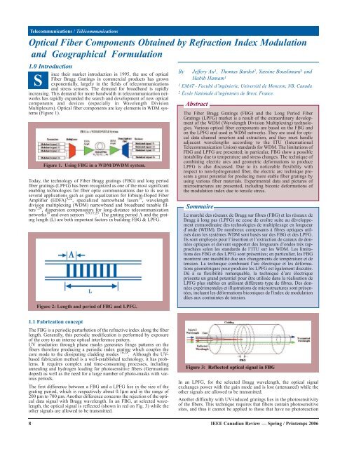
The first difference between a FBG and a LPFG lies in the size of the<br />
grating period, which is respectively about 0.1µm and in the range of<br />
200 µm to 700 µm. Another difference concerns the rejection of the optical<br />
data signal with Bragg wavelength. In an FBG, at selected wavelength,<br />
the optical signal is reflected (shown in red on Fig. 3) while the<br />
other signals are allowed to be transmitted.<br />
8<br />
Figure 3: Reflected optical signal in FBG<br />
In an LPFG, for the selected Bragg wavelength, the optical signal<br />
exchanges power with the gain mode and is lost (attenuated) while the<br />
other signals are allowed to be transmitted.<br />
Another difficulty with UV-induced gratings lies in the photosensitivity<br />
of the fibers. This technique requires that fibers contain photosensitive<br />
sites, and thus it cannot be applied to those that have no photoreaction<br />
<strong>IEEE</strong> Canadian Review — Spring / Printemps 2006
Figure 4. Attenuated optical signal in LPFG.<br />
centers inside 3, 20. But ultimately the UV grating inscription requires<br />
expensive and complex laser equipment.<br />
Recently, several photo-insensitive fabrication methods have been<br />
reported 1, 2, 3, 5, 6, 11, 12 , 21 which overcome some of the technological problems<br />
mentioned above while providing comparable results. Some fabrication<br />
methods have been demonstrated to be more stable, flexible, and<br />
possess additional useful properties.<br />
One of the assets of using the electric arc technique lies in the fact that<br />
it is so simple and flexible to use while offering a high thermal stability<br />
to the optical component. Studies 13,18 have demonstrated that the gratings<br />
implemented <strong>by</strong> the electric arc technique shows a wavelength shift<br />
caused <strong>by</strong> thermal variation of 0.07nm/100ºC compared to 5 –<br />
15nm/100ºC for UV induced gratings. The temperature sensitivity is<br />
related to the refractive index change on the outer cladding of an optical<br />
fiber. By using the electric arc technique, temperature insensitive LPFG<br />
were produced in this study, there<strong>by</strong> eliminating the deterring problem<br />
of unstable optical telecommunication components; more specifically<br />
building LPFG that is more robust to environmental stress and variations.<br />
The present paper will primarily focus on the electric-arc-based fabrication<br />
technique. This technique provides a high thermal stability in the<br />
LPFG 7,8,9,18 while using simple and inexpensive fabrication procedure<br />
and equipment. To better understand the usefulness of FBG and the<br />
LPFG, the limitations of these fiber components and their associated<br />
technologies should be investigated. In particular, the instability problem<br />
due to environmental changes is worth being investigated. The electricarc-based<br />
technique provides the flexibility to explore new non-conventional<br />
grating geometries, which have yet to be introduced. In particular,<br />
the technique of combining electric arcs and geometric deformation to<br />
produce LPFG will be discussed. For illustration purposes, one of the<br />
various microstructures including bi-conic deformation on the modulation<br />
index, due to tensile stress, will be presented. The prospects of the<br />
fibre gratings and the demands to overcome the present limitations will<br />
be presented at the end.<br />
2.0 Limitations with UV radiation technique<br />
In 1978, K. O. Hill et al 10 launched intense Argon-ion laser radiation<br />
into a Germanium-doped fiber and observed that after several minutes<br />
an increase in the reflected light intensity occurred which grew until<br />
almost all the light was reflected <strong>by</strong> the fiber. This achievement, subsequently<br />
called “Hill gratings,” was an outgrowth of research on the nonlinear<br />
properties of Germanium-doped silica fiber. This discovery later<br />
led to the UV inscribed fabrication process, which is performed <strong>by</strong> using<br />
the phase mask to create an interference pattern of UV beams in the core<br />
of an optical fiber there<strong>by</strong> modifying its refractive index along its axis.<br />
In a single mode FBG, these interferences patterns or gratings couple the<br />
fundamental mode to a contra-propagating for a resonant wavelength<br />
there<strong>by</strong> reflecting a specific wavelength when white light is injected into<br />
the particular fiber. On the other hand, in a single mode LPFG, the fundamental<br />
mode is not coupled with a contra-propagating mode. It’s coupled<br />
with several forward-propagating cladding modes for a resonant<br />
wavelength. These lasts decays rapidly as they propagate along the fiber<br />
therefore they can be used as band rejection filters.<br />
Figure 5. UV used for FBG writing through a phase mask<br />
The UV fabrication process is still the most common and readily used<br />
fabrication method in the industry 14 . However, it’s relatively complex<br />
and time-consuming as mentioned before. FBG and LPFG produced <strong>by</strong><br />
this method are also plagued <strong>by</strong> adverse environmental instabilities.<br />
These instabilities are caused <strong>by</strong> strain, bending and thermal sensitivity,<br />
doping concentrations, photosensitive degradation, polarization dependence,<br />
photo-induced birefringence and etc… Due to these weaknesses,<br />
FBG and LPFG based optical components have reached certain limitation<br />
especially in high-speed telecommunication applications. There is a<br />
definite technological requirement to overcome such limitation in order<br />
to further develop and improve the utilization of the FBG and LPFG<br />
based components in high-speed, all optical network applications.<br />
The instability due to sensitivity to temperature and stress is neither specific<br />
to fiber grating nor associated to the fabrication technique; the<br />
drawback is rather linked to the fiber material in which the gratings are<br />
recorded. In order to surmount and overcome this obstacle, new methods<br />
of fabricating fiber gratings have been reported. These fabrication<br />
processes offer many advantages and introduce the prospects of using<br />
different material composites to produce more stable fiber components.<br />
The use of electric arc is powerful and rentable fabrication technique.<br />
This method provides a simple, flexible and low cost means of producing<br />
LPFG with good overall performance. Moreover, LPFG can be written<br />
on any type of optical fiber with this method while providing a high<br />
thermal and mechanical stable optical component. The electric arc technique<br />
will also provide the flexibility to explore new non-conventional<br />
formations. In the following section, we’ll take a closer look at how this<br />
fabrication process works and the experimental results it produced.<br />
3.0 Experimental Setup<br />
There exist many diverse fiber grating fabrication methods. Each<br />
method has a different effect and analysis on the fiber grating knowledge<br />
that is essential to the total development of this evolving technology. The<br />
electric arc technique provides a very simple yet robust solution to some<br />
of the future LPFG development simply because it will allow<br />
researchers to explore new various geometric structures on different<br />
types and generations of optical fibers like the photonic crystal fibers.<br />
One of the greatest advantages of using the electric arc technique resides<br />
in the fact that it is so simple and flexible to use yet still providing a high<br />
thermal stability to the optical component it helps fabricate. Studies 13,18<br />
have demonstrated that the electric arc technique only has a thermal variation<br />
of 0.07nm/100ºC as compared to 5 – 15nm/100ºC on UV induced<br />
gratings. The temperature sensitivity has been related to the refractive<br />
index change on the outer cladding of an optical fiber. Using the electric<br />
arc technique, temperature insensitive LPFG were produced in this<br />
study, there<strong>by</strong> eliminating the deterring problem of unstable optical<br />
telecommunication components; more specifically building LPFG that is<br />
more resistant and robust to environmental stress and variations.<br />
Writing LPFG using the electrical arc technique consists of placing an<br />
uncoated optical fiber between the electrodes (Fig. 6) of either a splicing<br />
machine or an arc generator to induce a refractive index change.<br />
An electric arc, with an approximate diameter of 150um, is generated<br />
from the splicing machine creating a grating on the optical fiber. The<br />
fiber is then moved periodically to create a series of electrically induced<br />
gratings. White light is injected into one end of the optical fiber through<br />
a system of focalizing lenses while both end of the fiber are fixed to<br />
motorized translation stages that are co-controlled <strong>by</strong> a central computer.<br />
This will provide the option of either displacing the translation stages<br />
in unison or to explore the effects of applying micro-tensile stress on an<br />
optical fiber to create tapering. The other end of the optical fiber is connected<br />
to a spectral analyzer, where the spectral signal will be saved and<br />
analyzed. Once the splicing machine cover is closed an internal camera<br />
is used to visualize the micro-displacement of the optical fiber while the<br />
fabrication process is activated.<br />
<strong>IEEE</strong> Canadian Review — Spring / Printemps 2006 9
Not only are the translation<br />
stages connected to the central<br />
computer, but the spectral analyzer<br />
and the electric splicing<br />
machine are as well. The central<br />
computer system will oversee<br />
all the control and manipulation<br />
of the physical hardware<br />
of the entire experiment. The<br />
objective of having the experiment<br />
completely software driven<br />
is an attempt to completely<br />
isolate the experimental setup<br />
to prevent and/or minimize random<br />
human error, which can<br />
corrupt or affect the experimental<br />
data.<br />
A spectral analyzer is used to<br />
analyze the component output<br />
optical power. This optical signal<br />
is characterized while the<br />
gratings are inscribed on the<br />
optical fiber.<br />
The electric arcs serve to create<br />
periodic perturbations along the<br />
fiber <strong>by</strong> modifying the refractive<br />
index profile or the geometry<br />
of the fiber. These perturbations<br />
give rise to the LPFG coupling<br />
effect. In this case, the<br />
fundamental mode yields a part<br />
of its power to the various<br />
modes that are being propagated<br />
in the fiber (core and cladding<br />
modes). The coupling is carried<br />
out differently according to the<br />
wavelength, and the interaction<br />
between modes is characterized<br />
<strong>by</strong> an important attenuation of<br />
the output optical power for one<br />
wavelength.<br />
Figure 6. Refractive index changing using electric arc.<br />
4.0 Experimental results<br />
LPFG are fabricated with grating period that<br />
varies from 200-700nm while FBG have periods<br />
lower than 1um. Since the width of an electric arc<br />
is approximately 400um, it’s logical that the technique<br />
is more suitable to LPFG. Given that the<br />
electric arc technique provides the ability to use<br />
many different types of optical fiber, an adaptable<br />
and accommodating setup is necessary to unsure<br />
that flexibility is not lost on encumbering experimental<br />
support hardware. In another word, the<br />
flexibility of the technique has made it an ideal<br />
tool in exploring and analyzing optical components<br />
and new geometric formation generated <strong>by</strong><br />
fiber tapering. In figure Fig. 8 and for a 500µm<br />
LPFG period size, we have used a 1mA of the<br />
electrical-arc intensity without fiber elongation.<br />
After a several exposures to the electrical arc, the<br />
transmission spectrums show the output optical<br />
power attenuations for different durations of the<br />
arc.<br />
We note that the electric arc discharge can be used for writing and<br />
implementing the Long Period <strong>Fiber</strong> Bragg Gratings. The fiber doesn’t<br />
need to be a Germanium doped one. These techniques will also<br />
provide the flexibility to explore new non-conventional formations<br />
which have yet to be introduced. For the simulation we can use the<br />
coupled modes equations [2] to find out the fundamental mode output<br />
power at the output of the LPFG. The optical fiber can be considered<br />
as an ideal fiber with refractive index variations and core radius perturbations<br />
with considering a core modes and cladding modes propagation.<br />
After the fabrication process, the LPFG sensitivity to the temperature<br />
variations can be analyzed using the heating module mounted<br />
on the splicing machine.<br />
Figure 7. Experimental setup<br />
Transmission(dB)<br />
Wavelength (nm)<br />
Figure 8. Transmission spectrums for 500µm LPFGs.<br />
10<br />
<strong>IEEE</strong> Canadian Review — Spring / Printemps 2006
-65<br />
-70<br />
Transmission (dBm)<br />
-75<br />
-80<br />
-85<br />
-90<br />
20 °C<br />
100 °C<br />
150 °C<br />
200 °C<br />
220 °C<br />
-95<br />
1499<br />
1483<br />
1466<br />
1450<br />
1433<br />
1417<br />
1400<br />
1384<br />
1367<br />
1351<br />
1334<br />
1318<br />
1301<br />
Wavelength (nm)<br />
Figure 9. Figure spectrum senstivity to the temperature.<br />
As shown in Fig. 9, electric arc based fabrication techniques provide a<br />
thermal stability of the LPFG components. On this figure an important<br />
rejection of the optical signal around the wavelength 1367 nm. The vertical<br />
axis represents the attenuation in dBm (relative to 1mw power). We<br />
note that an attenuation of 3 dB represents 50% of rejection. The LPFG<br />
was exposed to different temperatures between 0°C and 220 °C. We<br />
Wavelength shift (nm)<br />
Temperature (°C)<br />
Figure 10. LPFG sensitivity to the temperature.<br />
observe that the wavelength spectrum shift to greater wavelengths. The<br />
sensitivity can be calculated after determination of the wavelength shift<br />
as function as the variation of the temperature. For the case shown<br />
before, the average wavelength shift is 11 nm (± 1nm) between 1300 nm<br />
et 1450 nm for a temperature variation of 200°C. The sensitivity will be<br />
around 0.055 nm/ °C (± 0.005nm/ °C). The figure below shows that the<br />
sensitivity seems to be linear as function of the temperature<br />
variations.<br />
The electric arc technique provides a very simple yet<br />
robust solution to some of the future LPFG development<br />
simply because it will allow researchers to explore new<br />
various geometric structures on different types and generations<br />
of optical fibers like the photonic crystal fibers.<br />
On the computer-controlled translation stage, the fiber can<br />
move with a precision under a micrometer. If the optical<br />
fiber is elongated under exposition, micro deformations<br />
can be produced on the fiber. The LPFG fabrication is<br />
accomplished <strong>by</strong> one or the both processes; <strong>by</strong> exposition<br />
to the arc discharge, and <strong>by</strong> elongating the fiber using the<br />
micro-displacement stage. These two methods create a<br />
permanent change of the refractive index of the fiber<br />
or/and modulate the effective index along the optical<br />
fiber. For micro-deformations we can use also a CO2 laser<br />
beam [2]. If the fiber core radius after deformation<br />
becomes smaller than the cut-off frequency radius, the<br />
core mode becomes a cladding one. At the output optical<br />
power is subjected to wavelength oscillations and rejections.<br />
Hence, in an LPFG device, optical power is<br />
exchanged between core and cladding modes. Periodic<br />
<strong>IEEE</strong> Canadian Review — Spring / Printemps 2006 11
type of fiber the gratings has been inscribed on; peak loss position<br />
obtained have varied. It demonstrates that the potential to create better<br />
optical component resides in the exploration and the research of new<br />
types and generation of optical fiber. Therefore <strong>by</strong> using the electric<br />
arc technique it will provide the necessary tool to possibly continue<br />
advancing this technology.<br />
0<br />
-5<br />
Transmission(dB)<br />
-10<br />
-15<br />
-20<br />
-25<br />
-30<br />
-35<br />
-40<br />
0.2 mm<br />
0.3 mm<br />
0.4 mm<br />
1000<br />
1050<br />
1099<br />
1149<br />
1198<br />
1248<br />
1297<br />
1347<br />
1396<br />
1446<br />
1495<br />
1545<br />
1594<br />
1644<br />
1693<br />
Wavelength (nm)<br />
Figure 11. LPFG with different elongation sizes.<br />
expositions of the optical fiber to the electrical arc produce a permanent<br />
and periodic modification of refractive indexes.<br />
The elongation distance is the most important parameter in the fabrication<br />
processes. As shown on the figure below we can produce an LPFG<br />
only with a few elongations if we use the right elongation distance. The<br />
transmission powers are measured for 200µm, 300µm and 400µm elongation<br />
sizes. The exposition duration is about 350ms; the period size is<br />
500µm.The effect of tension on grating formation was also studied in 19 ;<br />
<strong>by</strong> increasing the tension and keeping the arc parameters constant, it is<br />
possible to get higher isolation loss with less discharges although<br />
insertion loss increases. So with these results, we can say that the axial<br />
tension during the LPFG fabrication is favorable to the writing<br />
process. Also, it’s important to say that different tensions during the<br />
writing process produce different resonance wavelengths 19 .<br />
Experimental results have been obtained <strong>by</strong> combining the effects of<br />
electric arc and geometric deformation. The objective was to improve<br />
the quality and the efficiency of producing LPFG using electric arc <strong>by</strong><br />
manipulating other favorable external parameters. In our experiment<br />
we generated a series of electrically tapered grating in effort to analyze<br />
the combined effects on a LPFG. The result shows greater wavelength<br />
isolation was obtain as a result of combining the two effects. Even<br />
though an initial insertion loss was observed, the final result of the<br />
LPFG demonstrated a pronounced wavelength isolation with less<br />
inscriptions.<br />
In general, using the electric arc technique has produced comparable<br />
and useable wavelength isolation as compared to the conventional UV<br />
technique. Cutoff wavelengths with more than 25 db have been produced<br />
within the ranges of 1250 nm and 1600 nm. Depending on the<br />
12<br />
5.0 Prospect<br />
The advantage of this technique resides in the simplicity, flexibility and<br />
adaptability to study new generations of optical fibers. By using the<br />
unique characteristics of these fibers, we can explore and extract properties<br />
that will contribute and aide the progression of the development of<br />
useful optical component. One of the fibers that we are presently working<br />
on includes photonic crystal fibers. The effects of applying an electric<br />
arc across a holey fiber will be examined along with the use of other<br />
external parameter to create a useable optical component.<br />
Another advantage the electric arc technique provides is the ability to<br />
build a self-sustaining optical component-fabricating machine. Instead<br />
of simply buying an electric splicing machine, manufacturers can easily<br />
build a machine that not only splice optical fibers together but produces<br />
custom LPFG as well. This allows producing customized optical components<br />
suiting the user’s needs.<br />
6.0 Conclusion<br />
With the increase of the number of its applications and its fabrication, we<br />
can easily note that the long period fiber gratings are a booming technology.<br />
In addition to reducing the costs and the increase in the fabrication<br />
rate, every new fabrication method provides new types of LPFGs<br />
with new characteristics. Thus, LPFGs that are fabricated with a change<br />
<strong>IEEE</strong> Canadian Review — Spring / Printemps 2006
of the fiber’s macroscopic structure (using CO 2 laser or an electric arc)<br />
have a high thermal stability. Moreover, these new characteristics propose<br />
new application fields like high temperature applications for electric<br />
arc induced LPFGs.<br />
The high economic potential to construct a tool that will enable us to better<br />
understand the potentials and the possibilities of this enabling technology<br />
is definitely worth investigating. This technique is not only simple<br />
to use but will provide a suitable developments on new fibre material<br />
which may radically solve the instability problem.<br />
7.0 Acknowledgement<br />
The authors would like to thank the “Faculté des Études Supérieures et<br />
de la Recherche (FESR) de l’Université de Moncton” as well as the support<br />
of all the members of EMAT (research group on Electromagnetic<br />
Application and Telecommunication).<br />
8.0 References<br />
[1] M. Akiyama, K. Nishide, K. Shima, A. Wada, R. Yanauchi, “A novel<br />
long- period fiber grating using periodically released residual stress<br />
of pure-silica core fiber,” Proc. <strong>Optical</strong> <strong>Fiber</strong> Communication Conf.,<br />
pp.276-277, 1998.<br />
[2] Y. Bouslimani, H. Hamam, O. Latry and M. Ketata, “CO 2 laser beam<br />
based technique for producing optical fiber components”, SPIE Vol.<br />
5260, p154-162, 2003.<br />
[3] T. Enomoto, M. Shigehara, S. Ishikawa, T. Danzuka, H. Kanamori,<br />
“Long-period fiber grating in a pure-silica-core fiber written <strong>by</strong><br />
residual stress relaxation”, OFC Technical Digest, pp.277-278, 1998.<br />
[4] O. Frazão, G. Rego, M. Lima, A. Teixeira, F. M. Araújo, P. André,<br />
J. F. da Rocha, H. M. Salgado “EDFA Gain Flattening Using Long-<br />
Period Fibre Gratings Based on the Electric Arc Technique”,<br />
London Communications Symposium 2001,<br />
http://www.ee.ucl.ac.uk/lcs/prog01/LCS041.pdf<br />
[5] M. Fujimaki & Y. Ohki, “Fabrication of long-period optical fiber gratings<br />
<strong>by</strong> use of ion implantation,” Optics Letters., v. 25, pp. 88-89, 2000.<br />
[6] David C. Gerstenberger, “Method and apparatus for fiber Bragg<br />
grating production,” United States Patent Application,<br />
20030048523, www.utc.fr/~farges/recherche/recherche.htm, March<br />
13, 2003.<br />
[7] Y. G. Han, W. T. Han, U. C. Paek, Y. Chung, “Tunable Bandpass<br />
Filter with novel Core Mode Blocker Fabricated <strong>by</strong> Local Heat<br />
Exposure”, Kwangju Institute of Science & Technology, 2002,<br />
http://fdlab.kjist.ac.kr/mis/publications/data/2002/256.pdf<br />
[8] G. Humbert, A. Malki, “Temperature characterization of long-period<br />
fiber gratings fabricated with electric arc discharge”, Proc. SPIE Vol.<br />
4579, pp. 176-183, 10/2001.<br />
[9] G. Humbert, A. Malki, “Characterizations at very high temperature<br />
of electric arc-induced long-period fiber,” Opt. Commun. 208,<br />
pg.329-335, 2002.<br />
[10] K.O. Hill, D.-C. Johnson, B.-S. Kawasaki: “Photosensitivity in<br />
optical fiber waveguides: application to reflection filter fabrication”<br />
in Applied Physics Letters / Vol. 32, p. 647-649 / 1978<br />
[11] I. K. Hwang, S. H. Yun, and B. Y. Kim, “Long-period fiber gratings<br />
based on periodic microbends,” Optics Letters., vol.24, pp.1263-<br />
1265, 1999.<br />
[12] G. Kakarantzas, T. E. Dimmick, T. A. Birks, R. Le Roux, P. St. J.<br />
Russell, “Miniature all-fiber devices based on CO2 laser<br />
microstructuring of tapered fibers”, Optics Letters, Vol. 26, No. 15,<br />
August 1, 2001.<br />
[13] N. Godbout, X. Daxhelet, A. Maurier, and S. Lacroix, “Long Period<br />
<strong>Fiber</strong> Grating <strong>by</strong> Electric Discharge”, ECOC’98, pg 397-398,<br />
September 1998.<br />
[14] G. Meltz, W. W. Morey, and W. H. Glenn: “Formation of Bragg<br />
gratings in optical fibers <strong>by</strong> a transverse holographic method” in<br />
Opt. letters / Vol. 14, No. 15 / 1989.<br />
[15] R. M. Mead, “Method and apparatus for fiber Bragg grating production,”<br />
United States Patent Application, 20030007730,<br />
www.utc.fr/~farges/recherche/recherche.htm, January 9, 2003.<br />
[16] N. Fisher, “<strong>Fiber</strong> Bragg grating fabrication method,” United States<br />
Patent Application, 20030002795,<br />
www.utc.fr/~farges/recherche/recherche.htm, January 2, 2003.<br />
[17] Y. J. Rao, J. D. Jones, H. Naruse, R. I. Chen, “Novel mechanical<br />
fiber optic sensors based on long-period fiber gratings written <strong>by</strong><br />
high-frequency CO2 laser pulses”, Proc. SPIE Vol. 4920, pp 43-53,<br />
9/2002.<br />
[18] G. Rego, O. Okhotnikov, E. Dianov, V. Sulimov, “High-temperature<br />
stability of long-period fiber gratings produced using an electric<br />
arc,” Journal of Lightwave Technology, pp. 1574-1579, Vol.19,<br />
Issue 10, Oct. 2001.<br />
[19] G. Rego, M. Melo, J. L. Santos, H. M. Salgado “<strong>Optical</strong> Filters for<br />
Fibre Lasers and Amplifiers”, Portugal, 2002.<br />
[20] M. Vengsarkar, P. J. Lemaire, J. B. Judkins, V. Bhatia, T. Erdogan,<br />
and J. E. Sipe, “Long-period fiber gratings as band-rejection filters,”<br />
J. Lightwave Technol., vol. 14, pp. 58–65, Jan. 1996.<br />
[21] M. L. von Bibra, A. Roberts, J. Canning, “Fabrication of long-period<br />
fiber gratings <strong>by</strong> use of focused ion-beam irradiation,” Optics<br />
Letters, Vol. 26, Issue 11, pp. 765-767, June 2001.<br />
[22] Y. P. Wang, Y. J. Rao, Z. L. Ran, T. Zhu, A. Z. Hu, “Novel tunable<br />
gain equalizer based on a long-period fiber grating written <strong>by</strong> highfrequency<br />
CO 2 laser pulses”, Proc. SPIE Vol. 4906, pp. 180-184,<br />
8/2002.<br />
[23] H. Younggeun, K. Chang-Seok, P. Un-Chul, C. Youngjoo,<br />
“Performance Enhancement of Long Period <strong>Fiber</strong> Gratings for<br />
Strain and Temperature Sensing”, IEICE Trans Electron., vol. E83-<br />
C, No.3 March 2000.<br />
About the Authors<br />
Yassine Bouslimani joined the University of Moncton in<br />
July 2000. He received an Engineering degree from<br />
University of Batna (Algeria) in 1994, a Master degree<br />
from INSA of Rouen (France) in 1995 and a Ph. D. degree<br />
from University of Rouen (France) in 1999. Between 1996<br />
and 2000 he worked as a research and teaching assistant at<br />
the department of electrical and computer engineering of<br />
the University of Rouen. His research interests include the<br />
optical fiber components and the WDM (Wavelength<br />
Division Multiplexing) technologies. He works also on the<br />
Human-Machine interaction, on the electrical devices for<br />
people with reduced mobility and on the microcontroller<br />
applications in medical and industrial fields.<br />
Jeffery Au earned his B. Eng in electrical engineering<br />
from Université de Moncton (NB, Canada) in 2002. He is<br />
currently completing his graduate studies at the same university.<br />
He is research assistant at the EMAT Laboratory<br />
(ÉlectroMagnétisme Appliqué et Télécommunications) at<br />
the same university. His areas of interest include the fiber<br />
Bragg grating (FBG), the long period fiber grating (LPFG)<br />
and the fabrication mechanics of the optical fiber components.<br />
He is a student member of the Association of<br />
Professional Engineers and Geoscientists of New<br />
Brunswick (APEGNB).<br />
Thomas Bardot is currently completing his<br />
Engineering studies at the ENIB (ECOLE<br />
NATIONALE D’INGENIEURS DE BREST),<br />
France. Between Sep. 1994 and Jan. 1995 he worked as<br />
research assistant at the at the EMAT Laboratory<br />
(ÉlectroMagnétisme Appliqué et Télécommunications)<br />
at the University of Moncton. His research interests are<br />
the fiber Bragg grating (FBG) and the long period fiber<br />
grating (LPFG).<br />
Habib Hamam obtained the B.Eng. and M.Sc. degrees in information processing<br />
from the Technical University of Munich, Germany 1988 and 1992, and the Ph.D<br />
degree in telecommunications from Université de Rennes I jointly with the France<br />
Telecom Graduate School of Brittany, France 1995. He<br />
also obtained in 2004 a postdoctoral diploma in<br />
“Habilitation of Conducting Research in Signal Processing<br />
and Telecommunications” from Université de Rennes I.<br />
He is currently an associate Professor in the Department of<br />
Electrical Engineering at the Université de Moncton, with<br />
research interests in optical telecommunications, diffraction,<br />
fiber components, optics of the eye, biomedical engineering<br />
and E-Learning. He is an associate editor of the<br />
<strong>IEEE</strong> Canadian Review.<br />
<strong>IEEE</strong> Canadian Review — Spring / Printemps 2006 13
![Download Presentation [1.9MB PDF] - IEEE](https://img.yumpu.com/51364167/1/190x146/download-presentation-19mb-pdf-ieee.jpg?quality=85)

![Download Presentation [950KB PDF] - IEEE](https://img.yumpu.com/50598566/1/190x146/download-presentation-950kb-pdf-ieee.jpg?quality=85)