Optical Fiber Components Obtained by Refraction Index ... - IEEE
Optical Fiber Components Obtained by Refraction Index ... - IEEE
Optical Fiber Components Obtained by Refraction Index ... - IEEE

You also want an ePaper? Increase the reach of your titles
YUMPU automatically turns print PDFs into web optimized ePapers that Google loves.
-65<br />
-70<br />
Transmission (dBm)<br />
-75<br />
-80<br />
-85<br />
-90<br />
20 °C<br />
100 °C<br />
150 °C<br />
200 °C<br />
220 °C<br />
-95<br />
1499<br />
1483<br />
1466<br />
1450<br />
1433<br />
1417<br />
1400<br />
1384<br />
1367<br />
1351<br />
1334<br />
1318<br />
1301<br />
Wavelength (nm)<br />
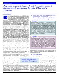
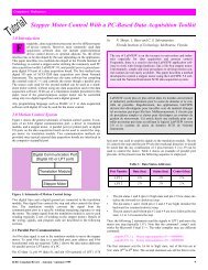
Figure 9. Figure spectrum senstivity to the temperature.<br />
As shown in Fig. 9, electric arc based fabrication techniques provide a<br />
thermal stability of the LPFG components. On this figure an important<br />
rejection of the optical signal around the wavelength 1367 nm. The vertical<br />
axis represents the attenuation in dBm (relative to 1mw power). We<br />
note that an attenuation of 3 dB represents 50% of rejection. The LPFG<br />
was exposed to different temperatures between 0°C and 220 °C. We<br />
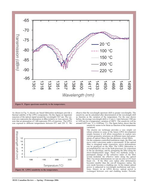
Wavelength shift (nm)<br />
Temperature (°C)<br />
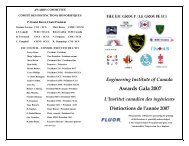
Figure 10. LPFG sensitivity to the temperature.<br />
observe that the wavelength spectrum shift to greater wavelengths. The<br />
sensitivity can be calculated after determination of the wavelength shift<br />
as function as the variation of the temperature. For the case shown<br />
before, the average wavelength shift is 11 nm (± 1nm) between 1300 nm<br />
et 1450 nm for a temperature variation of 200°C. The sensitivity will be<br />
around 0.055 nm/ °C (± 0.005nm/ °C). The figure below shows that the<br />
sensitivity seems to be linear as function of the temperature<br />
variations.<br />
The electric arc technique provides a very simple yet<br />
robust solution to some of the future LPFG development<br />
simply because it will allow researchers to explore new<br />
various geometric structures on different types and generations<br />
of optical fibers like the photonic crystal fibers.<br />
On the computer-controlled translation stage, the fiber can<br />
move with a precision under a micrometer. If the optical<br />
fiber is elongated under exposition, micro deformations<br />
can be produced on the fiber. The LPFG fabrication is<br />
accomplished <strong>by</strong> one or the both processes; <strong>by</strong> exposition<br />
to the arc discharge, and <strong>by</strong> elongating the fiber using the<br />
micro-displacement stage. These two methods create a<br />
permanent change of the refractive index of the fiber<br />
or/and modulate the effective index along the optical<br />
fiber. For micro-deformations we can use also a CO2 laser<br />
beam [2]. If the fiber core radius after deformation<br />
becomes smaller than the cut-off frequency radius, the<br />
core mode becomes a cladding one. At the output optical<br />
power is subjected to wavelength oscillations and rejections.<br />
Hence, in an LPFG device, optical power is<br />
exchanged between core and cladding modes. Periodic<br />
<strong>IEEE</strong> Canadian Review — Spring / Printemps 2006 11
![Download Presentation [1.9MB PDF] - IEEE](https://img.yumpu.com/51364167/1/190x146/download-presentation-19mb-pdf-ieee.jpg?quality=85)

![Download Presentation [950KB PDF] - IEEE](https://img.yumpu.com/50598566/1/190x146/download-presentation-950kb-pdf-ieee.jpg?quality=85)