Optical Fiber Components Obtained by Refraction Index ... - IEEE
Optical Fiber Components Obtained by Refraction Index ... - IEEE
Optical Fiber Components Obtained by Refraction Index ... - IEEE

You also want an ePaper? Increase the reach of your titles
YUMPU automatically turns print PDFs into web optimized ePapers that Google loves.
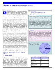
Not only are the translation<br />
stages connected to the central<br />
computer, but the spectral analyzer<br />
and the electric splicing<br />
machine are as well. The central<br />
computer system will oversee<br />
all the control and manipulation<br />
of the physical hardware<br />
of the entire experiment. The<br />
objective of having the experiment<br />
completely software driven<br />
is an attempt to completely<br />
isolate the experimental setup<br />
to prevent and/or minimize random<br />
human error, which can<br />
corrupt or affect the experimental<br />
data.<br />
A spectral analyzer is used to<br />
analyze the component output<br />
optical power. This optical signal<br />
is characterized while the<br />
gratings are inscribed on the<br />
optical fiber.<br />
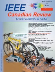
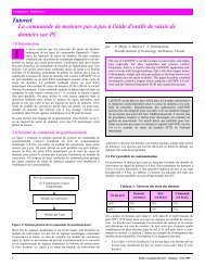
The electric arcs serve to create<br />
periodic perturbations along the<br />
fiber <strong>by</strong> modifying the refractive<br />
index profile or the geometry<br />
of the fiber. These perturbations<br />
give rise to the LPFG coupling<br />
effect. In this case, the<br />
fundamental mode yields a part<br />
of its power to the various<br />
modes that are being propagated<br />
in the fiber (core and cladding<br />
modes). The coupling is carried<br />
out differently according to the<br />
wavelength, and the interaction<br />
between modes is characterized<br />
<strong>by</strong> an important attenuation of<br />
the output optical power for one<br />
wavelength.<br />
Figure 6. Refractive index changing using electric arc.<br />
4.0 Experimental results<br />
LPFG are fabricated with grating period that<br />
varies from 200-700nm while FBG have periods<br />
lower than 1um. Since the width of an electric arc<br />
is approximately 400um, it’s logical that the technique<br />
is more suitable to LPFG. Given that the<br />
electric arc technique provides the ability to use<br />
many different types of optical fiber, an adaptable<br />
and accommodating setup is necessary to unsure<br />
that flexibility is not lost on encumbering experimental<br />
support hardware. In another word, the<br />
flexibility of the technique has made it an ideal<br />
tool in exploring and analyzing optical components<br />
and new geometric formation generated <strong>by</strong><br />
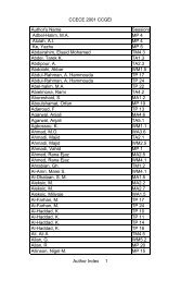
fiber tapering. In figure Fig. 8 and for a 500µm<br />
LPFG period size, we have used a 1mA of the<br />
electrical-arc intensity without fiber elongation.<br />
After a several exposures to the electrical arc, the<br />
transmission spectrums show the output optical<br />
power attenuations for different durations of the<br />
arc.<br />
We note that the electric arc discharge can be used for writing and<br />
implementing the Long Period <strong>Fiber</strong> Bragg Gratings. The fiber doesn’t<br />
need to be a Germanium doped one. These techniques will also<br />
provide the flexibility to explore new non-conventional formations<br />
which have yet to be introduced. For the simulation we can use the<br />
coupled modes equations [2] to find out the fundamental mode output<br />
power at the output of the LPFG. The optical fiber can be considered<br />
as an ideal fiber with refractive index variations and core radius perturbations<br />
with considering a core modes and cladding modes propagation.<br />
After the fabrication process, the LPFG sensitivity to the temperature<br />
variations can be analyzed using the heating module mounted<br />
on the splicing machine.<br />
Figure 7. Experimental setup<br />
Transmission(dB)<br />
Wavelength (nm)<br />
Figure 8. Transmission spectrums for 500µm LPFGs.<br />
10<br />
<strong>IEEE</strong> Canadian Review — Spring / Printemps 2006
![Download Presentation [1.9MB PDF] - IEEE](https://img.yumpu.com/51364167/1/190x146/download-presentation-19mb-pdf-ieee.jpg?quality=85)

![Download Presentation [950KB PDF] - IEEE](https://img.yumpu.com/50598566/1/190x146/download-presentation-950kb-pdf-ieee.jpg?quality=85)