An introduction to Micro CT Scanning
An introduction to Micro CT Scanning
An introduction to Micro CT Scanning
- No tags were found...
You also want an ePaper? Increase the reach of your titles
YUMPU automatically turns print PDFs into web optimized ePapers that Google loves.
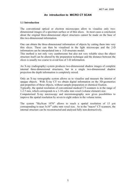
M<strong>CT</strong> okt. 2008<strong>An</strong> <strong>introduction</strong> <strong>to</strong> MICRO <strong>CT</strong> SCAN1.1 IntroductionThe conventional optical or electron microscopes allow <strong>to</strong> visualise only twodimensionalimages of a specimen surface or of thin slices. In most cases a conclusionabout the original three-dimensional object structures cannot be made on the base ofthis two-dimensional information.One can obtain the three-dimensional information of objects by cutting them in<strong>to</strong> verythin slices. These can then be visualised in the light microscope and the 2-Dinformation can be interpolated in<strong>to</strong> a 3-D structure model.This method is not only very cumbersome but also not very reliable since the objectstructure itself can be altered by the preparation technique and the distance between theslices is usually <strong>to</strong>o coarse <strong>to</strong> avoid loss of 3-D information.<strong>An</strong> X-ray (radiography) system produces two-dimensional shadow images of completeinternal three-dimensional structures, but in a single two-dimensional shadowprojection the depth information is completely mixed.Only an X-ray <strong>to</strong>mography system allows us <strong>to</strong> visualise and measure the interior ofopaque objects. With X-ray <strong>CT</strong> we obtain digital information on the 3D-geometriesand properties of these objects, without sample preparation or chemical fixation.Typically, the spatial resolution of conventional medical <strong>CT</strong>-scanners is in the range of1-2.5 mm, which corresponds <strong>to</strong> a 1-10 cubic mm voxel (volume element) size.Computerised X-ray microscopy and micro<strong>to</strong>mography now gives possibilities <strong>to</strong>improve the spatial resolution by seven <strong>to</strong> eight orders in the volume terms.The system "SkyScan 1076" allows <strong>to</strong> reach a spatial resolution of 15 µmcorresponding <strong>to</strong> near 3x10 -6 cubic mm voxel size. As in the "macro" <strong>CT</strong>-scanners, theinternal structure can be reconstructed and analysed fully non-destructively.1
M<strong>CT</strong> okt. 20081.2. Basic principles of micro<strong>to</strong>mogaphy“Tomos” is the Greek word for “cut” or “section”, and <strong>to</strong>mography is a technique fordigitally cutting a specimen open using X-rays <strong>to</strong> reveal its interior details. A <strong>CT</strong> imageis typically called a slice, as it corresponds <strong>to</strong> a slice from a loaf of bread. This analogyis apt, because just as a slice of bread has a thickness, a <strong>CT</strong> slice corresponds <strong>to</strong> acertain thickness of the object being scanned. Therefore, whereas a typical digitalimage is composed of pixels (picture elements), a <strong>CT</strong> slice image is composed of voxels(volume elements).<strong>An</strong> X-ray shadow image corresponds <strong>to</strong> a two-dimensional projection from the threedimensionalobject.In the simplest case, we can describe it as a parallel X-ray illumination. In thisapproximation, each point on the shadow image contains the integration of absorptioninformation inside the three-dimensional object in the corresponding partial X-raybeam.The X-rays that pass through the object they are scattered and/or absorbedThe gray levels in a <strong>CT</strong> slice correspond <strong>to</strong> X-ray attenuation, which reflects theproportion of X-rays scattered or absorbed as they pass through each voxel. X-rayattenuation is primarily a function of X-ray energy and the density and a<strong>to</strong>mic numberof the material being imaged. A <strong>CT</strong> image is created by directing X-rays through theslice plane from multiple orientations and measuring their resultant decrease inintensity. A specialized algorithm is then used <strong>to</strong> reconstruct the distribution of X-rayattenuation in the slice plane. By acquiring a stacked, contiguous series of <strong>CT</strong> images,data describing an entire volume can be obtained, in much the same way as a loaf ofbread can be reconstructed by stacking all of its slices.2
M<strong>CT</strong> okt. 2008A special algorithm is used <strong>to</strong> reconstruct the distribution of X-ray attenuation in theslice plane.How this reconstruction is done can be shown with a very simple example, namely anobject consisting of only one point with significant absorption in an unknown place.In the one-dimensional shadow line we will have a decrease of intensity of the shadowof absorption in the object area. (see figure on the next page)In the computer memory we now can initialise an empty array of pixels (pictureelements) corresponding <strong>to</strong> possible object displacement.Of course, one must be sure that all parts of the reconstructed object will be inside thefield of view. Because we have the position of the shadow from the absorption points ofthe object, we can mark in the area of reconstruction in the computer memory allpossible positions of absorption points inside the object as lines.Now let's rotate our object and repeat this operation ;Each new rotation position of the object will add <strong>to</strong> the area of reconstruction the linesof possible object positions corresponding <strong>to</strong> the position of the shadow.This operation is called "back-projection".After several rotations we can localise the position of the absorption point inside thearea of reconstruction. By increasing the number of shadow projections from differentviews this localisation becomes more and more defined.3
M<strong>CT</strong> okt. 2008corresponding <strong>to</strong> exponential law, we can res<strong>to</strong>re the linear absorption informationfrom the shadow image by logarithmisation.This operation is very non-linear and any noise in the small signal areas can producesignificant errors in reconstruction. To eliminate these errors an averaging of initial dataand results of logarithmisation can be used.On the other hand we can try <strong>to</strong> improve the signal <strong>to</strong> noise ratio in the shadow image<strong>to</strong> reach the most representative information.One more effective way of noise reduction in the reconstruction process is a specialselection of correction function for convolution before back projection.In the simplest case (described above) the correction function produces two "negativeabsorption" reactions around any signal or noise peak in the shadow line and thisbehaviour becomes very dangerous for noisy initial information.Special selection of convolution function for correction with spectral limitation by“Hamming window” allows solving this problem.In X-ray micro<strong>to</strong>mography information from voxels with very small physical sizeshould be detected and the right choice of parameters for noise reduction becomes veryimportant.5
M<strong>CT</strong> okt. 2008THE SKYSCAN 1076 SYSTEM OVERVIEWSPECIFICATIONS:Maximum object sizeX-ray sourceX-ray detec<strong>to</strong>rSpatial resolutionProjection / cross-sectionImage size and formats68mm(D) x 200mm(L) for rats or 35mm(D) x200mm(L) for mice, 17mm(L) per single scan20-100kV, 10W, 10000hestimated lifetime, air cooled sealed type, 4-positionsau<strong>to</strong>matic filter changer for energy selection10 Megapixel (4000x2300x12bit) cooled digitalX- ray camera with fibre-optic coupling <strong>to</strong> scintilla<strong>to</strong>rUser selectable pixel size 9µm / 18µm / 35µm(isotropic), 15µm low-contrast resolution (10% MTF)1000x520…8000x2000 pixels projection images (16-bit TIFF format)1000x1000…8000x8000 pixels cross-section (BMP,RAW 16-bit, TXT formats, converter <strong>to</strong> JPEG)X-ray loading <strong>to</strong> the animal 0.1-0.5 Gy per scan typical<strong>Scanning</strong> systemSoftware packageReconstruction algorithmRadiation safetyInstallation requirementsSize/Weightsource-detec<strong>to</strong>r pair rotation with 0.02 deg. min. stepsize, 50um object positioning accuracy with 400mmtravel, 50mm camera positioning/alignment with 1umaccuracy,
M<strong>CT</strong> okt. 2008The spatial resolution in a <strong>CT</strong> image is determined principally by the size and numberof detec<strong>to</strong>r elements, the size of the X-ray focal spot, and the source-object-detec<strong>to</strong>rdistances.The "SkyScan-1076" is a high- resolution low-dose X-ray scanner for in-vivo 3Dreconstructionwith a spatial resolution of up <strong>to</strong> 15 microns inside small labora<strong>to</strong>ryanimals (rats, mice, etc.).It consists of the combination of a micro-<strong>CT</strong> system and a computer with systemcontrol software and reconstruction software. This system allows reconstructing noninvasivelyany cross-section through the animal body with possibilities <strong>to</strong> convert thereconstructed dataset in<strong>to</strong> a realistic 3D-image and <strong>to</strong> calculate internal morphologicalparameters.The equipment contains an X-ray microfocus tube with high-voltage power supply, arotation stage with overall accuracy of
M<strong>CT</strong> okt. 2008For "SkyScan-1076” the X-ray microfocus tube with 5 micron focal spot size operatesat 20-100kV / 0-250µA.The special X-ray CCD-camera is based on 10 Megapixel (4000x2300 pixels) cooledCCD-sensor with fibre optic coupling <strong>to</strong> an X-ray scintilla<strong>to</strong>rThe X-ray shadow projections are digitised as 1000x520 <strong>to</strong> 8000x2000 pixels with4096 brightness gradations (12 bit).The reconstructed cross-sections have a 1000x1000 <strong>to</strong> 8000x8000 pixels (floatingpoint) format and 9 /18 /35µm pixel size in any place of the scanning area.The scanning area is 68mm x200mm or 35mm x 200mm (two carbon-composite bedssupplied)For the reconstruction one can use a volumetric (cone-beam) reconstruction of one /several / all cross-sections or a ROI-reconstruction. (ROI = Region of Interest)After the serial reconstruction, one can display the cross-sections on<strong>to</strong> the screen aswell as construct a realistic 3D-image with possibilities <strong>to</strong> "rotate" and "cut" the objectmodel.On this model, one can calculate the internal morphological parameters.10
11M<strong>CT</strong> okt. 2008


